EP0517543B1 - Ink jet recording method - Google Patents
Ink jet recording method Download PDFInfo
- Publication number
- EP0517543B1 EP0517543B1 EP92305185A EP92305185A EP0517543B1 EP 0517543 B1 EP0517543 B1 EP 0517543B1 EP 92305185 A EP92305185 A EP 92305185A EP 92305185 A EP92305185 A EP 92305185A EP 0517543 B1 EP0517543 B1 EP 0517543B1
- Authority
- EP
- European Patent Office
- Prior art keywords
- ink
- recording
- recording head
- area
- pixel
- Prior art date
- Legal status (The legal status is an assumption and is not a legal conclusion. Google has not performed a legal analysis and makes no representation as to the accuracy of the status listed.)
- Expired - Lifetime
Links
Images


Classifications
-
- H—ELECTRICITY
- H04—ELECTRIC COMMUNICATION TECHNIQUE
- H04N—PICTORIAL COMMUNICATION, e.g. TELEVISION
- H04N1/00—Scanning, transmission or reproduction of documents or the like, e.g. facsimile transmission; Details thereof
- H04N1/04—Scanning arrangements, i.e. arrangements for the displacement of active reading or reproducing elements relative to the original or reproducing medium, or vice versa
- H04N1/12—Scanning arrangements, i.e. arrangements for the displacement of active reading or reproducing elements relative to the original or reproducing medium, or vice versa using the sheet-feed movement or the medium-advance or the drum-rotation movement as the slow scanning component, e.g. arrangements for the main-scanning
- H04N1/126—Arrangements for the main scanning
- H04N1/128—Arrangements for the main scanning using a scanning head arranged for linear reciprocating motion
-
- B—PERFORMING OPERATIONS; TRANSPORTING
- B41—PRINTING; LINING MACHINES; TYPEWRITERS; STAMPS
- B41J—TYPEWRITERS; SELECTIVE PRINTING MECHANISMS, i.e. MECHANISMS PRINTING OTHERWISE THAN FROM A FORME; CORRECTION OF TYPOGRAPHICAL ERRORS
- B41J2/00—Typewriters or selective printing mechanisms characterised by the printing or marking process for which they are designed
- B41J2/005—Typewriters or selective printing mechanisms characterised by the printing or marking process for which they are designed characterised by bringing liquid or particles selectively into contact with a printing material
- B41J2/01—Ink jet
- B41J2/21—Ink jet for multi-colour printing
- B41J2/2121—Ink jet for multi-colour printing characterised by dot size, e.g. combinations of printed dots of different diameter
- B41J2/2128—Ink jet for multi-colour printing characterised by dot size, e.g. combinations of printed dots of different diameter by means of energy modulation
-
- B—PERFORMING OPERATIONS; TRANSPORTING
- B41—PRINTING; LINING MACHINES; TYPEWRITERS; STAMPS
- B41J—TYPEWRITERS; SELECTIVE PRINTING MECHANISMS, i.e. MECHANISMS PRINTING OTHERWISE THAN FROM A FORME; CORRECTION OF TYPOGRAPHICAL ERRORS
- B41J2/00—Typewriters or selective printing mechanisms characterised by the printing or marking process for which they are designed
- B41J2/005—Typewriters or selective printing mechanisms characterised by the printing or marking process for which they are designed characterised by bringing liquid or particles selectively into contact with a printing material
- B41J2/01—Ink jet
- B41J2/21—Ink jet for multi-colour printing
- B41J2/2132—Print quality control characterised by dot disposition, e.g. for reducing white stripes or banding
-
- G—PHYSICS
- G06—COMPUTING OR CALCULATING; COUNTING
- G06K—GRAPHICAL DATA READING; PRESENTATION OF DATA; RECORD CARRIERS; HANDLING RECORD CARRIERS
- G06K15/00—Arrangements for producing a permanent visual presentation of the output data, e.g. computer output printers
- G06K15/02—Arrangements for producing a permanent visual presentation of the output data, e.g. computer output printers using printers
- G06K15/10—Arrangements for producing a permanent visual presentation of the output data, e.g. computer output printers using printers by matrix printers
- G06K15/102—Arrangements for producing a permanent visual presentation of the output data, e.g. computer output printers using printers by matrix printers using ink jet print heads
- G06K15/105—Multipass or interlaced printing
- G06K15/107—Mask selection
-
- H—ELECTRICITY
- H04—ELECTRIC COMMUNICATION TECHNIQUE
- H04N—PICTORIAL COMMUNICATION, e.g. TELEVISION
- H04N1/00—Scanning, transmission or reproduction of documents or the like, e.g. facsimile transmission; Details thereof
- H04N1/04—Scanning arrangements, i.e. arrangements for the displacement of active reading or reproducing elements relative to the original or reproducing medium, or vice versa
- H04N1/19—Scanning arrangements, i.e. arrangements for the displacement of active reading or reproducing elements relative to the original or reproducing medium, or vice versa using multi-element arrays
- H04N1/191—Scanning arrangements, i.e. arrangements for the displacement of active reading or reproducing elements relative to the original or reproducing medium, or vice versa using multi-element arrays the array comprising a one-dimensional [1D] array
- H04N1/1911—Simultaneously or substantially simultaneously scanning picture elements on more than one main scanning line, e.g. scanning in swaths
-
- G—PHYSICS
- G06—COMPUTING OR CALCULATING; COUNTING
- G06K—GRAPHICAL DATA READING; PRESENTATION OF DATA; RECORD CARRIERS; HANDLING RECORD CARRIERS
- G06K2215/00—Arrangements for producing a permanent visual presentation of the output data
- G06K2215/101—Arrangements for producing a permanent visual presentation of the output data involving the use of ink jets
-
- G—PHYSICS
- G06—COMPUTING OR CALCULATING; COUNTING
- G06K—GRAPHICAL DATA READING; PRESENTATION OF DATA; RECORD CARRIERS; HANDLING RECORD CARRIERS
- G06K2215/00—Arrangements for producing a permanent visual presentation of the output data
- G06K2215/111—Arrangements for producing a permanent visual presentation of the output data with overlapping swaths
-
- H—ELECTRICITY
- H04—ELECTRIC COMMUNICATION TECHNIQUE
- H04N—PICTORIAL COMMUNICATION, e.g. TELEVISION
- H04N2201/00—Indexing scheme relating to scanning, transmission or reproduction of documents or the like, and to details thereof
- H04N2201/04—Scanning arrangements
- H04N2201/0402—Arrangements not specific to a particular one of the scanning methods covered by groups H04N1/04 - H04N1/207
- H04N2201/0414—Scanning an image in a series of overlapping zones
Definitions
- the present invention relates to an ink-jet recording method for generating clear images by using a recording apparatus including an ink-jet recording head having a plurality of orifices.
- a so-called multi-droplet method has been conventionally used for representing a tone wedge or gradation of a recording image.
- the multi-droplet method a plurality of ink droplets are deposited at substantially the same position on a recording medium, and a pixel having an area according to the number of the plurality of ink droplets is formed.
- the tone wedge of the recording image is represented by forming a pixel having an area according to the image data.
- the recording head is moved (main-scanning) relative to a recording medium for recording a part of the images, and then the recording head is moved (sub-scanning) perpendicularly to the direction of main-scanning and the main-scanning is carried out for recording another part of the images That is, the main-scanning and the sub-scanning are carried out by turns so that all the images are recorded on the recording medium.
- the above feed distance of the recording head in the sub-scanning direction is a distance which is a distance between two orifices provided on the recording head or a distance determined by the product of an orifice pitch and the number of orifices.
- the feed distance in the sub-scanning direction is determined as the above described distance value, a portion not recorded of a so-called "white stripe banding" is generated in a recording image when an actual feed distance is greater than the predetermined distance value.
- the actual feed distance is smaller than the predetermined value, there is a problem that ink droplets, the number of which is about twice as large as the number of ink droplets forming a predetermined pixel, land on the same position and a portion of a so-called "black stripe banding" of an extremely high image density is generated.
- the feed distance in the sub-scanning direction may be precisely controlled so as to be always constant under any condition. However, this causes a very expensive manufacturing cost of the ink-jet recording apparatus.
- volume of one ink droplet, which is discharged from one orifice in a vicinity of an edge portion of orifices disposed in a row may fluctuate due to a temperature distribution in the use of the ink-jet recording head or unevenness of products caused by manufacturing a machining processes.
- unevenness of the image density may occur between portions recorded by the orifices in the vicinity of the edge portions of the recording head and portions recorded by other orifices.
- the image quality in a vicinity of a boundary between an image area recorded in main-scanning and an image area recorded in next main-scanning may deteriorate for the above reasons.
- EP-0,376,596 discloses a printer in which a single pixel is normally formed by two ink droplets discharged from different nozzles and is accordingly not concerned with the above discussed problems.
- ink jet recording apparatus as set out in claim 7.
- An embodiment of the present invention markedly reduces unevenness of an image density, resulting from a "black stripe” or a "white stripe” generated in a vicinity of a boundary between an image area formed in main-scanning and an image area formed in next main-scanning by simple control.
- An embodiment of the present invention improves image quality of image areas including the boundary.
- Fig. 1 is a schematic perspective view of an ink-jet recording apparatus of embodiment 1 according to the present invention.
- reference numeral 1 denotes a recording head on which 128 ink orifices are disposed at a density of 16 orifices/mm.
- Each of orifices is provided with an electrothermal transducer for generating energy used for discharging ink in an ink path communicating to the orifice.
- term “discharging portion", “outlet” or “nozzle” may be used instead of term “orifice”.
- the electrothermal transducer generates heat in response to electric pulses applied thereto and then generates film boiling in ink with this heat, so that ink is discharged from the orifice according to the film boiling.
- the discharging frequency or the driving frequency for driving the electrothermal transducer is 2kHz.
- Reference numeral 174 denotes a carriage for mounting and shifting the recording head 1.
- the carriage 174 is guided and shifted along two guide shafts 175A and 175B being slidably engaged with the carriage 174.
- Reference numeral 176 denotes an ink supplying tube which supplies ink from an ink tank (not shown) to the recording head 1.
- Reference numeral 177 denotes a flexible cable for transmitting driving signals and control signals based on recording data from a control unit of the recording apparatus (not shown) to the recording head driver being provided in a portion of the recording head 1.
- the ink supplying tube 176 and the flexible cable 177 are made of flexible members so that they can follow the movement of the carriage 174.
- the carriage 174 is connected to part of a belt (not shown) being stretched in parallel to the guide shafts 175A and 175B for shifting the carriage 174, and can be shifted by the belt driven by a carriage motor (not shown).
- Reference numeral 173 denotes a platen whose longitudinal direction is parallel to the guide shafts 175A and 175B.
- Reference numeral 172 denotes a recording sheet as a recording medium.
- the recording head 1 discharges ink in process of the movement of the carriage 174, so that an image area is recorded on a portion of the recording sheet 172 opposite to the orifices.
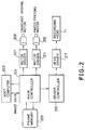
- Fig. 2 is a block diagram showing a control circuit of the recording apparatus shown in Fig. 1.
- Reference numeral 201 denotes a main controller which controls the whole recording apparatus including the discharging timing, and is usually composed of a one-chip microprocessor or the like with a central processing unit (CPU), a read-only memory which stored a program (program ROM) and a random access memory used for work (work RAM) or the like.
- the main controller accepts image data signals for indicating the image density of each pixel from a host computer 203, and then stores the signals in units of frames onto a frame memory 205 as a buffer.
- the main controller 201 controls the drive of a carriage feed motor 209 via a first motor driver 207, and also controls a recording sheet feed motor 213 via a second motor driver 211.
- the main controller 201 reads image data from the frame memory 205, converts the image data into tone wedge data suitable for the recording apparatus, controls the ink discharging by the recording head 1 (explained hereinafter in more detail) via the driver controller 215 and a head driver 217, and then performs recording of tone wedge image on a recording sheet 172 whereby.
- Embodiment 1 for performing 17-tone-wedge image recording by using the above described recording apparatus will be described below.
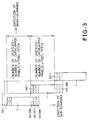
- Fig. 3 is a diagram explaining the positional relationship of the recording head 1 relative to the recording sheet 172 each time the recording head 1 is main-scans.
- reference numeral 1 denotes a schematic diagram of the recording head 1 on which orifices are disposed in the vertical direction.
- the orifices are numbered 1, 2, ..., 128 in the top-to-bottom direction.
- positions of the recording head 1 are assumed to be shifted in the main-scanning direction. But, actually, each left side portion of the recording head 1 at each starting point of main-scanning is placed in the same vertical position.
- N number
- the orifices Nos. 1, 2, ..., and 128 are used.
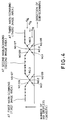
- the numbers of ink droplets discharged from the orifices Nos. 126, 127 and 128 are determined as N x 6/8, N x 4/8 and N x 2/8 respectively for forming the first image area.
- a recording sheet is moved or sub-scanned upward by 125 pixels so that the orifices Nos. 1, 2, and 3 overlap part of the first image area formed by the orifices Nos. 126, 127 and 128 respectively, in the second main-scanning (in Fig. 3, the recording head 1 is moved downward relative to a recording sheet for convenience), and the orifice No. 1 is placed to the position of the orifice No. 126 in the first main-scanning.
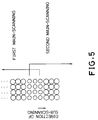
- the second image area is recorded at the second main-scanning in such a way that the numbers of ink droplets discharged from the orifices Nos. 1, 2 and 3 are N x 2/8, N x 4/8 and N x 6/8 respectively and the numbers of ink droplets discharged from the orifices Nos. 126, 127 and 128 are N x 6/8, N x 4/8 and N x 2/8, respectively as shown in Fig. 4.
- the overlapped portion of the first and second image areas is shown in Fig. 5.
- the recording of image area is repeated to form all the image areas of the images on the sheet.
- image recording is performed in such a way that the numbers of ink droplets discharged from the orifices Nos. 126, 127 and 128 are the same as the number of ink droplets discharged from the orifices Nos. 4 to 125.
- pixels of recording image are made of the same number of ink droplets.
- the number of ink droplets forming each pixel according to image data differs from each other, and the number (N') of ink droplets (image density data) forming each pixel to be overlapped is multiplied by 2/8, 4/8, 6/8 or the like.
- the values 2/8, 4/8, 6/8 and the like can be adjusted for each recording head according to the volume of an ink droplet.
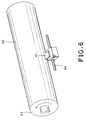
- Fig. 6 is a view showing construction of embodiment 2 of the recording apparatus according to the present invention.
- Reference numeral 41 denotes an ink-jet recording head having 512 orifices (at a density of 16 orifices/mm). The orifices are disposed in the lateral direction of Fig. 6.
- the recording head 41 is movable along a rail 44.
- Reference numerals 42 and 43 denote a recording sheet and a drum driven by a motor (not shown) respectively.
- the 17-tone-wedge recording can be performed by the recording apparatus of embodiment 2.
- the number of orifices to perform overlapping image recording is two for each edge portion of the recording head.
- the recording head 41 is positioned to the leftmost position in Fig. 6, and as shown in Fig. 7, image density data of the orifices Nos. 511 and 512 are made to be N x 6/8 and N x 2/8 respectively, and the drum 43 is made to make one revolution to perform the first image recording.
- the recording head 41 is shifted to the right by 511 pixel pitches, image density data of the orifices Nos. 1, 2, 511 and 512 are made to be N x 2/8, N x 6/8, N x 6/8 and N x 2/8 respectively to perform the second image recording.
- the drum 43 is made to make one revolution. The above processing is repeated to perform recording of all the image areas. In the rightmost image area of the images on the sheet, like embodiment 1, the above processing is not performed on image density data of the orifices Nos. 511 and 512.
- embodiment 1 there are three orifices to perform overlapping recording for each edge portion of the recording head, and in embodiment 2, there are two orifices to perform the overlapping recording for each edge portion of the recording head.
- the number of orifices performing the overlapping recording is optionally selectable less than the number of all the orifices.
- values by which image density data are multiplied are standardized with respect to 1/2 n in order to be easily treated by hardware. However, it is not necessary to standardize the values based on 1/2 n . For example, as shown in embodiment 3 in Fig. 8, if there are three overlapping orifices, the values can be 1/10, 1/2 and 9/10. In any case, the total of landed ink droplets may correspond to original image density data.
- ink droplets when one pixel is recorded in the overlapping image area, ink droplets are landed on substantially the same area twice at predetermined interval.
- a plurality of ink droplets to land at a first time or at a second time are defined by a first or second ink droplet group.
- the amount of the first or second ink droplet group landed at the first time or the second time in a central pixel in the overlapping portion of image areas is about a half of the amount of the ink droplets to be landed on a pixel on non-overlapping portion, so that the spread of the first ink droplet group on a recording medium is smaller than that of ink droplets landed on the pixel on the non-overlapping portion.
- a predetermined time is passed after the first main scanning, and then a previously landed the first ink droplet group is fixed in some degrees.
- the final size of the pixel is smaller than the size when the all the ink droplets are landed on the pixel at a time.
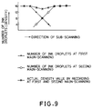
- the size of pixel in an overlapping portion of image areas shown in Fig. 5 is smaller than the size of another pixel, and the image density of the overlapping portion becomes low.
- the image density distribution in this case is shown in Fig. 9.
- the size of one pixel formed by the dots is made larger by shifting a position of the landed first ink droplet from a position of the landed second ink droplet. This can reduce unevenness of the image density in the overlapping portion of the image areas.
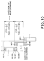
- Fig. 10 is a schematic diagram for explaining a recording method of embodiment 4, and like reference numerals designate like parts in Figs. 3 and 10.
- Image area recording will be described below in which the number of orifices for recording an overlapping portion of the two image areas is three for each edge portion of the recording head and the highest image density of the overlapping area is formed by 16 ink droplets.
- the orifices Nos. 1 to 128 are used and the orifices 126, 127 and 128 discharge 12, 8 and 4 ink droplets respectively.
- the recording sheet is moved or subscanned upward by 125 plus 1/3 pixel pitches (for convenience, the recording head 1 is moved downward relative to the recording sheet in Fig. 10).
- the numbers of ink droplets discharged from the orifices Nos. 1, 2 and 3 are 4, 8 and 12, and the numbers of ink droplets discharged from the orifices Nos. 126, 127 and 128 are 12, 8 and 4 respectively.
- the recording sheet is moved upward by 125 minus 1/3 pixel pitches and the same numbers of ink droplets as described above are discharged on the recording sheet to perform recording.
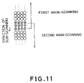
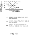
- the area of pixels forming the overlapping portion between a first image area and a second image area can be widened by the above described recording method. Consequently, as shown in Fig. 12, the area of pixel forming the overlapping portion can be made approximately equal to an area of pixel forming another portion edge of the image area, and unevenness of the image density generated in the overlapping area can be markedly reduced.
- five-tone-wedge recording is performed by using the ink-jet recording apparatus in Fig. 6.
- 128 orifices (16 orifices/mm) are disposed in the lateral direction of the recording head.
- the number of orifices which record an overlapping portion is two for each edge portion of the recording head, and the highest image density of a pixel in the overlapping portion is formed by four ink droplets.
- the recording head 41 is positioned to the leftmost position in Fig. 6. While the numbers of ink droplets discharged from the orifices Nos. 127 and 128 are 3 and 1 respectively, recording is performed during rotating the drum 43. At this time, a recording start position in the direction of the drum revolution is defined as H.
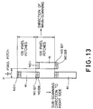
- the recording head 41 is shifted to the right by 126 pixel pitches as shown in Fig. 13.
- the numbers of ink droplets discharged from the orifices Nos. 1 and 2 are one and three
- the numbers of ink droplets discharged from the orifices Nos. 127 and 128 are three and one respectively so as to record a second image area.
- the recording start position in the direction of the drum revolution is shifted from the record starting position H by 0.5 pixel pitch so as to start recording.
- the recording head 41 is shifted to the right by 126 pixel pitches as shown in Fig. 13, and then, recording is performed at the recording start position H with the same numbers of ink droplets as described above.
- Fig. 15 illustrates the recording result of pixels recorded by the recording apparatus of embodiment 5.
- Fig. 16 is the construction of an ink-jet recording apparatus of embodiment 6 according to the present invention.
- Reference numeral 141 denotes an ink-jet recording head having 512 orifices (16 orifices/mm), and being disposed obliquely to the direction of revolution of the drum 41.
- the other construction is similar to the recording apparatus shown in Fig. 6.
- the recording head 141 is first located on the right side of the drum 42, and is shifted from the right side to the left side by 510 plus 1/2 pixel pitches during one revolution of the drum 43. That is, sub-scanning of the recording head 141 has been completed when main-scanning in which the drum 43 makes one revolution is completed.
- orifices are numbered 1, 2, ..., and 512 from the right side in Fig. 16, the number of orifices which perform overlapping portion are two for each edge portion of the recording head, and a pixel in the overlapping portion is generated by eight ink droplets.
- the drum 43 makes one revolution so as to finish recording of the first image area.
- the recording head 141 has been shifted to the left by 510 plus 1/2 pixel pitches
- the orifice No. 1 is shifted to the left by 1/2 pixel pitch from a position in which orifice No. 511 was located first
- orifice No. 2 is shifted to the left by 1/2 pixel pitch from a position in which orifice 512 was located first.
- the numbers of ink droplets discharged from orifices Nos. 1, 2, 511 and 512 are four, and the second image area and the latter are formed.
- the numbers of ink droplets discharged from only orifices Nos. 1 and 2 are four. Thus, recording of all the image areas has been completed.
- the unevenness of image density, a "black stripe” or a “white stripe”, which is generated in a vicinity of a boundary between each recorded image area at each main-scanning, is markedly reduced by simple control, and hence the image quality is improved in the vicinity of the boundary between each image area.
- the present invention achieves distinct effect when applied to a recording head or a recording apparatus which has means for generating thermal energy such as electrothermal transducers or laser light, and which causes changes in the ink by the thermal energy so as to eject ink. This is because such a system can achieve a high density and high resolution recording.
- the on-demand type apparatus has electrothermal transducers, each disposed on a sheet or liquid passage that retains liquid (ink), and operates as follows: first, one or more drive signals are applied to the electrothermal transducers to cause thermal energy corresponding to recording information; second, the thermal energy induces sudden temperature rise that exceeds the nucleate boiling so as to cause the film boiling on heating portions of the recording head; and third, bubbles are grown in the liquid (ink) corresponding to the drive signals. By using the growth and collapse of the bubbles, the ink is expelled from at least one of the ink ejection orifices of the head to form one or more ink drops.
- the drive signal in the form of a pulse is preferable because the growth and collapse of the bubbles can be achieved instantaneously and suitably by this form of drive signal.
- a drive signal in the form of a pulse those described in U.S. patent Nos. 4,463,359 and 4,345,262 are preferable.
- the rate of temperature rise of the heating portions described in U.S. patent No. 4,313,124 be adopted to achieve better recording.
- U.S. patent Nos. 4,558,333 and 4,459,600 disclose the following structure of a recording head, which is incorporated to the present invention: this structure includes heating portions disposed on bent portions in addition to a combination of the ejection orifices, liquid passages and the electrothermal transducers disclosed in the above patents. Moreover, the present invention can be applied to structures disclosed in Japanese Patent Application Laying-open Nos. 123670/1984 and 138461/1984 in order to achieve similar effects.
- the former discloses a structure in which a slit common to all the thermoelectric transducers is used as ejection orifices of the electrothermal transducers, and the latter discloses a structure in which openings for absorbing pressure waves caused by thermal energy are formed corresponding to the ejection orifices.
- the present invention can be applied to various serial type recording heads: a recording head fixed to the main assembly of a recording apparatus; a conveniently replaceable chip type recording head which, when loaded on the main assembly of a recording apparatus, is electrically connected to the main assembly, and is supplied with ink therefrom; and a cartridge type recording head integrally including an ink reservoir.
- a recovery system or a preliminary auxiliary system for a recording head as a constituent of the recording apparatus because they serve to make the effect of the present invention more reliable.
- the recovery system are a capping means and a cleaning means for the recording head, and a pressure or suction means for the recording head.
- the preliminary auxiliary system are a preliminary heating means utilizing electrothermal transducers or a combination of other heater elements and the electrothermal transducers, and a means for carrying out preliminary ejection of ink independently of the ejection for recording. These systems are effective for reliable recording.
- the number and type of recording heads to be mounted on a recording apparatus can be also changed. For example, only one recording head corresponding to a single color ink, or a plurality of recording heads corresponding to a plurality of inks different in color or concentration can be used.
- the present invention can be effectively applied to an apparatus having at least one of the monochromatic, multi-color and full-color modes.
- the monochromatic mode performs recording by using only one major color such as black.
- the multi-color mode carries out recording by using different color inks, and the full-color mode performs recording by color mixing.
- inks that are liquid when the recording signal is applied can be used: for example, inks can be employed that solidify at a temperature lower than the room temperature and are softened or liquefied in the room temperature. This is because in the ink jet system, the ink is generally temperature adjusted in a range of 30°C - 70°C so that the viscosity of the ink is maintained at such a value that the ink can be ejected reliably.
- the present invention can be applied to such apparatus where the ink is liquefied just before the ejection by the thermal energy as follows so that the ink is expelled from the orifices in the liquid state, and then begins to solidify on hitting the recording medium, thereby preventing the ink evaporation: the ink is transformed from solid to liquid state by positively utilizing the thermal energy which would otherwise cause the temperature rise; or the ink, which is dry when left in air, is liquefied in response to the thermal energy of the recording signal.
- the ink may be retained in recesses or through holes formed in a porous sheet as liquid or solid substances so that the ink faces the electrothermal transducers as described in Japanese Patent Application Laying-open Nos. 56847/1979 or 71260/1985.
- the present invention is most effective when it uses the film boiling phenomenon to expel the ink.
- the ink jet recording apparatus of the present invention can be employed not only as an image output terminal of an information processing device such as a computer, but also as an output device of a copying machine including a reader, as an output device of a facsimile apparatus having a transmission and receiving function, and as an output device of an optical disc apparatus for recording and/or reproducing information into and/or from an optical disc.
- an information processing device such as a computer
- an output device of a copying machine including a reader as an output device of a facsimile apparatus having a transmission and receiving function
- an optical disc apparatus for recording and/or reproducing information into and/or from an optical disc.
Landscapes
- Engineering & Computer Science (AREA)
- Physics & Mathematics (AREA)
- Multimedia (AREA)
- General Engineering & Computer Science (AREA)
- General Physics & Mathematics (AREA)
- Theoretical Computer Science (AREA)
- Mathematical Physics (AREA)
- Signal Processing (AREA)
- Quality & Reliability (AREA)
- Ink Jet (AREA)
- Particle Formation And Scattering Control In Inkjet Printers (AREA)
- Chemical Or Physical Treatment Of Fibers (AREA)
- Glass Compositions (AREA)
- Optical Recording Or Reproduction (AREA)
Abstract
Description
- The present invention relates to an ink-jet recording method for generating clear images by using a recording apparatus including an ink-jet recording head having a plurality of orifices.
- In an ink-jet recording method for recording images on a recording medium such as a recording sheet by moving (main-scanning) an ink-jet recording head with a plurality of orifices relative to the recording medium, a so-called multi-droplet method has been conventionally used for representing a tone wedge or gradation of a recording image. In the multi-droplet method, a plurality of ink droplets are deposited at substantially the same position on a recording medium, and a pixel having an area according to the number of the plurality of ink droplets is formed. In this case, the tone wedge of the recording image is represented by forming a pixel having an area according to the image data.
- When the multi-droplet method is used for recording images, all the images are generally recorded in such a way that the recording head is moved (main-scanning) relative to a recording medium for recording a part of the images, and then the recording head is moved (sub-scanning) perpendicularly to the direction of main-scanning and the main-scanning is carried out for recording another part of the images That is, the main-scanning and the sub-scanning are carried out by turns so that all the images are recorded on the recording medium. In the conventional ink-jet recording method, the above feed distance of the recording head in the sub-scanning direction is a distance which is a distance between two orifices provided on the recording head or a distance determined by the product of an orifice pitch and the number of orifices.
- In the conventional ink-jet recording method, since, however, the feed distance in the sub-scanning direction is determined as the above described distance value, a portion not recorded of a so-called "white stripe banding" is generated in a recording image when an actual feed distance is greater than the predetermined distance value. On the other hand, when the actual feed distance is smaller than the predetermined value, there is a problem that ink droplets, the number of which is about twice as large as the number of ink droplets forming a predetermined pixel, land on the same position and a portion of a so-called "black stripe banding" of an extremely high image density is generated. In order to solve these problems, the feed distance in the sub-scanning direction may be precisely controlled so as to be always constant under any condition. However, this causes a very expensive manufacturing cost of the ink-jet recording apparatus.
- Moreover, in the ink-jet recording head, volume of one ink droplet, which is discharged from one orifice in a vicinity of an edge portion of orifices disposed in a row, may fluctuate due to a temperature distribution in the use of the ink-jet recording head or unevenness of products caused by manufacturing a machining processes. As a result, in an image area, recorded in one main-scanning, unevenness of the image density may occur between portions recorded by the orifices in the vicinity of the edge portions of the recording head and portions recorded by other orifices.
- As described above, in the conventional ink-jet recording method, the image quality in a vicinity of a boundary between an image area recorded in main-scanning and an image area recorded in next main-scanning may deteriorate for the above reasons.
- European Patent Specification No. EP-0,376,596 discloses a printer in which a single pixel is normally formed by two ink droplets discharged from different nozzles and is accordingly not concerned with the above discussed problems.
- In accordance with a first aspect of the present invention there is provided a method of ink jet recording as set out in
claim 1. - In accordance with a second aspect of the present invention there is provided ink jet recording apparatus as set out in claim 7.
- An embodiment of the present invention markedly reduces unevenness of an image density, resulting from a "black stripe" or a "white stripe" generated in a vicinity of a boundary between an image area formed in main-scanning and an image area formed in next main-scanning by simple control.
- An embodiment of the present invention improves image quality of image areas including the boundary.
- The above and other effects, features and advantages of the present invention will become more apparent from the following description of embodiments thereof taken in conjunction with the accompanying drawings and given by way of example.
- Fig. 1 is a schematic perspective view of an ink-jet recording apparatus of
embodiment 1 according to the present invention; - Fig. 2 is a block diagram of a control circuit of the ink-jet recording apparatus shown in Fig. 1;
- Fig. 3 is a diagram explaining positions of a recording head relative to a recording medium of
embodiment 1 according to the present invention shown in Fig. 1; - Fig. 4 is a diagram showing the number of ink droplets discharged from each orifice of the recording head of
embodiment 1 according to the present invention; - Fig. 5 is a diagram showing a recorded result of
embodiment 1 of the present invention; - Fig. 6 is a view showing a schematic perspective view of an ink-jet recording apparatus of
embodiment 2 according to the present invention; - Fig. 7 is a diagram showing the number of ink droplets discharged from each orifice of the recording head of
embodiment 2 according to the present invention; - Fig. 8 is a diagram showing the number of ink droplets discharged from each orifice of the recording head of
embodiment 3 according to the present invention; - Fig. 9 is a diagram showing the relationship between the number of ink droplets and the image density for each pixel in
embodiment 1 of the present invention; - Fig. 10 is a diagram explaining positions of the recording head relative to a recording medium of
embodiment 4 according to the present invention; - Fig. 11 is a diagram showing a recorded result of
embodiment 4 of the present invention; - Fig. 12 is a diagram showing the relationship between the number of ink droplets and the image density for each pixel in
embodiment 4 of the present invention; - Fig. 13 is a diagram explaining positions of the recording head relative to a recording medium of embodiment 5 according to the present invention;
- Fig. 14 is a diagram showing the relationship between the number of ink droplets and the image density for each pixel in embodiment 5 of the present invention;
- Fig. 15 is a diagram showing a recorded result of embodiment 5 of the present invention;
- Fig. 16 is a view showing a schematic perspective view of an ink-jet recording apparatus of
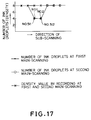
embodiment 6 according to the present invention; - Fig. 17 is a diagram showing the relationship between the number of ink droplets and the image density for each pixel in
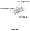
embodiment 6 according to the present invention; and - Fig. 18 is a diagram showing a recorded result of
embodiment 6 of the present invention. - Referring to the accompanying drawings, embodiments of the present invention will be described below.
- Fig. 1 is a schematic perspective view of an ink-jet recording apparatus of
embodiment 1 according to the present invention. In Fig. 1,reference numeral 1 denotes a recording head on which 128 ink orifices are disposed at a density of 16 orifices/mm. Each of orifices is provided with an electrothermal transducer for generating energy used for discharging ink in an ink path communicating to the orifice. Incidentally, in embodiments described here and hereinafter of the present invention, term "discharging portion", "outlet" or "nozzle" may be used instead of term "orifice". The electrothermal transducer generates heat in response to electric pulses applied thereto and then generates film boiling in ink with this heat, so that ink is discharged from the orifice according to the film boiling. Inembodiment 1, the discharging frequency or the driving frequency for driving the electrothermal transducer is 2kHz. -
Reference numeral 174 denotes a carriage for mounting and shifting therecording head 1. Thecarriage 174 is guided and shifted along twoguide shafts 175A and 175B being slidably engaged with thecarriage 174.Reference numeral 176 denotes an ink supplying tube which supplies ink from an ink tank (not shown) to therecording head 1.Reference numeral 177 denotes a flexible cable for transmitting driving signals and control signals based on recording data from a control unit of the recording apparatus (not shown) to the recording head driver being provided in a portion of therecording head 1. Theink supplying tube 176 and theflexible cable 177 are made of flexible members so that they can follow the movement of thecarriage 174. Thecarriage 174 is connected to part of a belt (not shown) being stretched in parallel to theguide shafts 175A and 175B for shifting thecarriage 174, and can be shifted by the belt driven by a carriage motor (not shown). -
Reference numeral 173 denotes a platen whose longitudinal direction is parallel to theguide shafts 175A and 175B.Reference numeral 172 denotes a recording sheet as a recording medium. - The
recording head 1 discharges ink in process of the movement of thecarriage 174, so that an image area is recorded on a portion of therecording sheet 172 opposite to the orifices. - Fig. 2 is a block diagram showing a control circuit of the recording apparatus shown in Fig. 1.
Reference numeral 201 denotes a main controller which controls the whole recording apparatus including the discharging timing, and is usually composed of a one-chip microprocessor or the like with a central processing unit (CPU), a read-only memory which stored a program (program ROM) and a random access memory used for work (work RAM) or the like. The main controller accepts image data signals for indicating the image density of each pixel from ahost computer 203, and then stores the signals in units of frames onto aframe memory 205 as a buffer. When images are recorded, that is, when ink is discharged, themain controller 201 controls the drive of acarriage feed motor 209 via afirst motor driver 207, and also controls a recordingsheet feed motor 213 via asecond motor driver 211. Themain controller 201 reads image data from theframe memory 205, converts the image data into tone wedge data suitable for the recording apparatus, controls the ink discharging by the recording head 1 (explained hereinafter in more detail) via thedriver controller 215 and ahead driver 217, and then performs recording of tone wedge image on arecording sheet 172 whereby. -
Embodiment 1 for performing 17-tone-wedge image recording by using the above described recording apparatus will be described below. - Fig. 3 is a diagram explaining the positional relationship of the
recording head 1 relative to therecording sheet 172 each time therecording head 1 is main-scans. In Fig. 3,reference numeral 1 denotes a schematic diagram of therecording head 1 on which orifices are disposed in the vertical direction. For the sake of explanation, the orifices are numbered 1, 2, ..., 128 in the top-to-bottom direction. In Fig. 3, positions of therecording head 1 are assumed to be shifted in the main-scanning direction. But, actually, each left side portion of therecording head 1 at each starting point of main-scanning is placed in the same vertical position. For the sake of explanation, it is assumed that the density of all the images to be recorded on a recording sheet is uniform, that is, each pixel on the sheet is assumed to be generated from the same number (N) of ink droplets. - When recording is performed on the recording sheet at the first main-scanning time, the orifices Nos. 1, 2, ..., and 128 are used. At this time, as shown in Fig. 4, the numbers of ink droplets discharged from the orifices Nos. 126, 127 and 128 are determined as N x 6/8, N x 4/8 and N x 2/8 respectively for forming the first image area.
- Next, as shown in Fig. 3, a recording sheet is moved or sub-scanned upward by 125 pixels so that the orifices Nos. 1, 2, and 3 overlap part of the first image area formed by the orifices Nos. 126, 127 and 128 respectively, in the second main-scanning (in Fig. 3, the
recording head 1 is moved downward relative to a recording sheet for convenience), and the orifice No. 1 is placed to the position of the orifice No. 126 in the first main-scanning. - After the completion of the above sub-scanning, the second image area is recorded at the second main-scanning in such a way that the numbers of ink droplets discharged from the orifices Nos. 1, 2 and 3 are N x 2/8, N x 4/8 and N x 6/8 respectively and the numbers of ink droplets discharged from the orifices Nos. 126, 127 and 128 are N x 6/8, N x 4/8 and N x 2/8, respectively as shown in Fig. 4. The overlapped portion of the first and second image areas is shown in Fig. 5.
- Similarly, the recording of image area is repeated to form all the image areas of the images on the sheet. At the lowest image area of the images on the sheet, image recording is performed in such a way that the numbers of ink droplets discharged from the orifices Nos. 126, 127 and 128 are the same as the number of ink droplets discharged from the orifices Nos. 4 to 125.
- Moreover, in the above explanation of the image recording, it has been assumed that pixels of recording image are made of the same number of ink droplets. Actually, the number of ink droplets forming each pixel according to image data differs from each other, and the number (N') of ink droplets (image density data) forming each pixel to be overlapped is multiplied by 2/8, 4/8, 6/8 or the like.
- Moreover, if a volume of an ink droplet discharged from each orifice in a central portion of the recording head extremely differs from that in edge portions thereof, the
values 2/8, 4/8, 6/8 and the like can be adjusted for each recording head according to the volume of an ink droplet. - Fig. 6 is a view showing construction of
embodiment 2 of the recording apparatus according to the present invention.Reference numeral 41 denotes an ink-jet recording head having 512 orifices (at a density of 16 orifices/mm). The orifices are disposed in the lateral direction of Fig. 6. Therecording head 41 is movable along arail 44.Reference numerals - The 17-tone-wedge recording can be performed by the recording apparatus of
embodiment 2. The number of orifices to perform overlapping image recording is two for each edge portion of the recording head. - First, the
recording head 41 is positioned to the leftmost position in Fig. 6, and as shown in Fig. 7, image density data of the orifices Nos. 511 and 512 are made to be N x 6/8 and N x 2/8 respectively, and thedrum 43 is made to make one revolution to perform the first image recording. - Next, the
recording head 41 is shifted to the right by 511 pixel pitches, image density data of the orifices Nos. 1, 2, 511 and 512 are made to be N x 2/8, N x 6/8, N x 6/8 and N x 2/8 respectively to perform the second image recording. After the recording head is shifted to the right by 511 pixel pitches as shown above, thedrum 43 is made to make one revolution. The above processing is repeated to perform recording of all the image areas. In the rightmost image area of the images on the sheet, likeembodiment 1, the above processing is not performed on image density data of the orifices Nos. 511 and 512. - In
embodiment 1, there are three orifices to perform overlapping recording for each edge portion of the recording head, and inembodiment 2, there are two orifices to perform the overlapping recording for each edge portion of the recording head. However, the number of orifices performing the overlapping recording is optionally selectable less than the number of all the orifices. - In
embodiments embodiment 3 in Fig. 8, if there are three overlapping orifices, the values can be 1/10, 1/2 and 9/10. In any case, the total of landed ink droplets may correspond to original image density data. - In the above embodiments, when one pixel is recorded in the overlapping image area, ink droplets are landed on substantially the same area twice at predetermined interval. A plurality of ink droplets to land at a first time or at a second time are defined by a first or second ink droplet group. For example, in Fig. 5, the amount of the first or second ink droplet group landed at the first time or the second time in a central pixel in the overlapping portion of image areas, is about a half of the amount of the ink droplets to be landed on a pixel on non-overlapping portion, so that the spread of the first ink droplet group on a recording medium is smaller than that of ink droplets landed on the pixel on the non-overlapping portion. Moreover, a predetermined time is passed after the first main scanning, and then a previously landed the first ink droplet group is fixed in some degrees. In this state, when a next ink droplet group, the second ink droplet group, is landed on the same pixel on the recording sheet, the final size of the pixel is smaller than the size when the all the ink droplets are landed on the pixel at a time. When the number of pixels in the main-scanning direction is extremely large, the previously landed ink droplet group has been mostly fixed and the final size of the pixel becomes smaller than the size corresponding to the original image density data. The reason is that it takes a long time to record image data in the main-scanning direction.
- For instance, if it takes a relatively long time to perform one main-scanning due to the large number of pixels to be recorded in the main-scanning direction, the size of pixel in an overlapping portion of image areas shown in Fig. 5 is smaller than the size of another pixel, and the image density of the overlapping portion becomes low. The image density distribution in this case is shown in Fig. 9.
- In the embodiment described below, when a dot formed by landing a first ink droplet group on a recording medium portionally overlaps with a dot formed by landing a second ink droplet group on the recording medium, the size of one pixel formed by the dots is made larger by shifting a position of the landed first ink droplet from a position of the landed second ink droplet. This can reduce unevenness of the image density in the overlapping portion of the image areas.
- In
embodiment 4, 17-tone-wedge recording is performed by using the ink-jet recording apparatus shown in Fig. 1. Fig. 10 is a schematic diagram for explaining a recording method ofembodiment 4, and like reference numerals designate like parts in Figs. 3 and 10. - Image area recording will be described below in which the number of orifices for recording an overlapping portion of the two image areas is three for each edge portion of the recording head and the highest image density of the overlapping area is formed by 16 ink droplets.
- When recording is performed on a recording sheet, the orifices Nos. 1 to 128 are used and the
orifices discharge - Next, the recording sheet is moved or subscanned upward by 125 plus 1/3 pixel pitches (for convenience, the
recording head 1 is moved downward relative to the recording sheet in Fig. 10). - Moreover, the numbers of ink droplets discharged from the orifices Nos. 1, 2 and 3 are 4, 8 and 12, and the numbers of ink droplets discharged from the orifices Nos. 126, 127 and 128 are 12, 8 and 4 respectively.
- Next, the recording sheet is moved upward by 125 minus 1/3 pixel pitches and the same numbers of ink droplets as described above are discharged on the recording sheet to perform recording.
- The above described operations are alternately repeated and finally all the image areas are formed.
- As shown in Fig. 11, the area of pixels forming the overlapping portion between a first image area and a second image area can be widened by the above described recording method. Consequently, as shown in Fig. 12, the area of pixel forming the overlapping portion can be made approximately equal to an area of pixel forming another portion edge of the image area, and unevenness of the image density generated in the overlapping area can be markedly reduced.
- In embodiment 5, five-tone-wedge recording is performed by using the ink-jet recording apparatus in Fig. 6. However, in
embodiment 5, 128 orifices (16 orifices/mm) are disposed in the lateral direction of the recording head. - The number of orifices which record an overlapping portion is two for each edge portion of the recording head, and the highest image density of a pixel in the overlapping portion is formed by four ink droplets.
- First, the
recording head 41 is positioned to the leftmost position in Fig. 6. While the numbers of ink droplets discharged from the orifices Nos. 127 and 128 are 3 and 1 respectively, recording is performed during rotating thedrum 43. At this time, a recording start position in the direction of the drum revolution is defined as H. - Next, the
recording head 41 is shifted to the right by 126 pixel pitches as shown in Fig. 13. After this sub-scanning, as shown in Fig. 14, the numbers of ink droplets discharged from the orifices Nos. 1 and 2 are one and three, and the numbers of ink droplets discharged from the orifices Nos. 127 and 128 are three and one respectively so as to record a second image area. At this time, as shown in Fig. 13, the recording start position in the direction of the drum revolution is shifted from the record starting position H by 0.5 pixel pitch so as to start recording. - After the second image area has been formed, the
recording head 41 is shifted to the right by 126 pixel pitches as shown in Fig. 13, and then, recording is performed at the recording start position H with the same numbers of ink droplets as described above. - The above described operations are repeated to perform recording of all the image areas. Fig. 15 illustrates the recording result of pixels recorded by the recording apparatus of embodiment 5.
- Fig. 16 is the construction of an ink-jet recording apparatus of
embodiment 6 according to the present invention.Reference numeral 141 denotes an ink-jet recording head having 512 orifices (16 orifices/mm), and being disposed obliquely to the direction of revolution of thedrum 41. The other construction is similar to the recording apparatus shown in Fig. 6. - The
recording head 141 is first located on the right side of thedrum 42, and is shifted from the right side to the left side by 510 plus 1/2 pixel pitches during one revolution of thedrum 43. That is, sub-scanning of therecording head 141 has been completed when main-scanning in which thedrum 43 makes one revolution is completed. - In
embodiment 6, orifices are numbered 1, 2, ..., and 512 from the right side in Fig. 16, the number of orifices which perform overlapping portion are two for each edge portion of the recording head, and a pixel in the overlapping portion is generated by eight ink droplets. - First, when the first image area is formed or until the
drum 43 makes a first revolution, eight ink droplets are discharged from orifices Nos. 1 to 510 and four ink droplets are discharged from orifices Nos. 511 and 512 so as to perform recording. - Thus, the first image area is formed, and the
drum 43 makes one revolution so as to finish recording of the first image area. When the the recording has been completed and the drum starts making a second revolution, therecording head 141 has been shifted to the left by 510 plus 1/2 pixel pitches, the orifice No. 1 is shifted to the left by 1/2 pixel pitch from a position in which orifice No. 511 was located first, and orifice No. 2 is shifted to the left by 1/2 pixel pitch from a position in which orifice 512 was located first. - Next, the numbers of ink droplets discharged from orifices Nos. 1, 2, 511 and 512 are four, and the second image area and the latter are formed.
- When the last image area is formed, the numbers of ink droplets discharged from only orifices Nos. 1 and 2 are four. Thus, recording of all the image areas has been completed.
- The state of pixels in a boundary between each image area in
embodiment 6 is shown in Fig. 18. - According to the present invention, the unevenness of image density, a "black stripe" or a "white stripe", which is generated in a vicinity of a boundary between each recorded image area at each main-scanning, is markedly reduced by simple control, and hence the image quality is improved in the vicinity of the boundary between each image area.
- The present invention achieves distinct effect when applied to a recording head or a recording apparatus which has means for generating thermal energy such as electrothermal transducers or laser light, and which causes changes in the ink by the thermal energy so as to eject ink. This is because such a system can achieve a high density and high resolution recording.
- A typical structure and operational principle thereof is disclosed in U.S. patent Nos. 4,723,129 and 4,740,796, and it is preferable to use this basic principle to implement such a system. Although this system can be applied either to on-demand type or continuous type ink jet recording systems, it is particularly suitable for the on-demand type apparatus. This is because the on-demand type apparatus has electrothermal transducers, each disposed on a sheet or liquid passage that retains liquid (ink), and operates as follows: first, one or more drive signals are applied to the electrothermal transducers to cause thermal energy corresponding to recording information; second, the thermal energy induces sudden temperature rise that exceeds the nucleate boiling so as to cause the film boiling on heating portions of the recording head; and third, bubbles are grown in the liquid (ink) corresponding to the drive signals. By using the growth and collapse of the bubbles, the ink is expelled from at least one of the ink ejection orifices of the head to form one or more ink drops. The drive signal in the form of a pulse is preferable because the growth and collapse of the bubbles can be achieved instantaneously and suitably by this form of drive signal. As a drive signal in the form of a pulse, those described in U.S. patent Nos. 4,463,359 and 4,345,262 are preferable. In addition, it is preferable that the rate of temperature rise of the heating portions described in U.S. patent No. 4,313,124 be adopted to achieve better recording.
- U.S. patent Nos. 4,558,333 and 4,459,600 disclose the following structure of a recording head, which is incorporated to the present invention: this structure includes heating portions disposed on bent portions in addition to a combination of the ejection orifices, liquid passages and the electrothermal transducers disclosed in the above patents. Moreover, the present invention can be applied to structures disclosed in Japanese Patent Application Laying-open Nos. 123670/1984 and 138461/1984 in order to achieve similar effects. The former discloses a structure in which a slit common to all the thermoelectric transducers is used as ejection orifices of the electrothermal transducers, and the latter discloses a structure in which openings for absorbing pressure waves caused by thermal energy are formed corresponding to the ejection orifices. Thus, irrespective of the type of the recording head, the present invention can achieve recording positively and effectively.
- In addition, the present invention can be applied to various serial type recording heads: a recording head fixed to the main assembly of a recording apparatus; a conveniently replaceable chip type recording head which, when loaded on the main assembly of a recording apparatus, is electrically connected to the main assembly, and is supplied with ink therefrom; and a cartridge type recording head integrally including an ink reservoir.
- It is further preferable to add a recovery system, or a preliminary auxiliary system for a recording head as a constituent of the recording apparatus because they serve to make the effect of the present invention more reliable. As examples of the recovery system, are a capping means and a cleaning means for the recording head, and a pressure or suction means for the recording head. As examples of the preliminary auxiliary system, are a preliminary heating means utilizing electrothermal transducers or a combination of other heater elements and the electrothermal transducers, and a means for carrying out preliminary ejection of ink independently of the ejection for recording. These systems are effective for reliable recording.
- The number and type of recording heads to be mounted on a recording apparatus can be also changed. For example, only one recording head corresponding to a single color ink, or a plurality of recording heads corresponding to a plurality of inks different in color or concentration can be used. In other words, the present invention can be effectively applied to an apparatus having at least one of the monochromatic, multi-color and full-color modes. Here, the monochromatic mode performs recording by using only one major color such as black. The multi-color mode carries out recording by using different color inks, and the full-color mode performs recording by color mixing.
- Furthermore, although the above-described embodiments use liquid ink, inks that are liquid when the recording signal is applied can be used: for example, inks can be employed that solidify at a temperature lower than the room temperature and are softened or liquefied in the room temperature. This is because in the ink jet system, the ink is generally temperature adjusted in a range of 30°C - 70°C so that the viscosity of the ink is maintained at such a value that the ink can be ejected reliably.
- In addition, the present invention can be applied to such apparatus where the ink is liquefied just before the ejection by the thermal energy as follows so that the ink is expelled from the orifices in the liquid state, and then begins to solidify on hitting the recording medium, thereby preventing the ink evaporation: the ink is transformed from solid to liquid state by positively utilizing the thermal energy which would otherwise cause the temperature rise; or the ink, which is dry when left in air, is liquefied in response to the thermal energy of the recording signal. In such cases, the ink may be retained in recesses or through holes formed in a porous sheet as liquid or solid substances so that the ink faces the electrothermal transducers as described in Japanese Patent Application Laying-open Nos. 56847/1979 or 71260/1985. The present invention is most effective when it uses the film boiling phenomenon to expel the ink.
- Furthermore, the ink jet recording apparatus of the present invention can be employed not only as an image output terminal of an information processing device such as a computer, but also as an output device of a copying machine including a reader, as an output device of a facsimile apparatus having a transmission and receiving function, and as an output device of an optical disc apparatus for recording and/or reproducing information into and/or from an optical disc. These apparatus requires means for outputting processed information in the form of hard copy.
- The present invention has been described in detail with respect to preferred embodiments, and it will now be apparent from the foregoing to those skilled in the art that changes and modifications may be made without departing from the invention in its broader aspects, and it is the intention, therefore, in the appended claims to cover all such changes and modifications as fall within the true spirit of the invention.
Claims (14)
- A method of recording an image on a recording medium using a recording head (1) having at least one array of ejection orifices for ejecting ink to record pixels of the image on the recording medium, which method comprises recording one portion of the image by effecting relative scanning of the recording head (1) and the recording medium in a main scanning direction extending transversely of the ejection orifice array; effecting relative movement of the recording head (1) and the recording medium in a sub-scanning direction extending perpendicular to the main scan direction; and then recording another image portion by effecting relative movement between the recording head (1) and the recording medium in the main scanning direction while causing the ejection orifice to eject ink, the relative movement between the recording head and the recording medium in the sub-scanning direction between the main scans causing the area scanned by the succeeding main scan to overlap partially the area scanned by the preceding main scan, characterised by recording tonal gradations in the image by controlling the area of each pixel by controlling the amount of ink ejected by the recording head to form that pixel and generating a required tonal gradation in the area of overlap by controlling the ejection of ink from the ejection orifices scanning over the area of overlap so that, during the first main scan, the amount of ink ejected by the ejection orifices scanning the eventual area of overlap is progressively reduced in the sub-scanning direction and, during the succeeding main scan, the amount of ink ejected by the ejection orifices scanning over the area of overlap is progressively increased, so that the total quantity of ink ejected for the area of overlap during the two scans corresponds to the amount of ink which would have been ejected in a single scan of a non-overlap area.
- A method according to claim 1, wherein the amount of ink deposited for a pixel is increased by increasing the number of ejection orifice ink discharges for the pixel.
- A method according to claim 1, wherein the amount of ink deposited for a pixel corresponds to the number of ejection orifice ink discharges for that pixel.
- A method according to claim 1, 2 or 3, wherein the amount of relative movement between the recording head and the recording medium in the sub-scan direction is set to be a non-integer multiple of the spacing of the ejection orifices in the sub-scan direction.
- A method according to any one of the preceding claims, which comprises using a thermal ink jet recording head.
- A method according to any one of the preceding claims for multi-colour recording.
- Ink jet recording apparatus for recording an image on a recording medium using a recording head (1) having at least one array of ejection orifices for ejecting ink to record pixels of the image on the recording medium, which apparatus comprises means (174, 175A-B, 207, 209) for effecting relative scanning of the recording head (1) and the recording medium in a main scanning direction extending transversely of the ejection orifice array; means (211, 213) for effecting relative movement of the recording head (1) and the recording medium in a sub-scanning direction extending perpendicular to the main scan direction following a main scan; and control means (201) adapted to cause respective portions of the image to be recorded in successive main scans and to cause the area scanned by the succeeding main scan to overlap partially the area scanned by the preceding main scan, characterised in that, in order to record tonal gradations in an image, the control means (201) is adapted to control the area of each pixel by controlling the amount of ink ejected by the recording head to form that pixel and to generate a required tonal gradation in the area of overlap by controlling the ejection of ink from the ejection orifices scanning over the area of overlap so that, during the first main scan, the amount of ink ejected by the ejection orifices scanning the eventual area of overlap is progressively reduced in the sub-scanning direction and, during the succeeding main scan, the amount of ink ejected by the ejection orifices scanning over the area of overlap is progressively increased, so that the total quantity of ink ejected for the area of overlap during the two scans corresponds to the amount of ink which would have been ejected in a single scan of a non-overlap area.
- Apparatus according to claim 7, wherein the control means (201) is adapted to increase the amount of ink deposited for a pixel by increasing the number of ejection orifice ink discharges for the pixel.
- Apparatus according to claim 7, wherein the control means (201) is adapted to control the amount of ink deposited for a pixel by controlling the number of ejection orifice ink discharges for that pixel.
- Apparatus according to claim 7, 8 or 9, wherein the amount of relative movement between the recording head and the recording medium in the sub-scan direction is set by the control means to be a non-integer multiple of the spacing of the ejection orifices in the sub-scan direction.
- Apparatus according to claim 7, 8, 9 or 10, wherein the recording head is a thermal ink jet head.
- Apparatus according to any one of claims 7 to 11, wherein the apparatus is adapted for colour recording.
- Apparatus according to any one of claims 7 to 12 and including recovery means for carrying out recovery processing on the recording head.
- Ink jet recording apparatus according to any one of claims 7 to 13 and incorporated in a facsimile machine, or a copying machine or a computer terminal.
Applications Claiming Priority (2)
| Application Number | Priority Date | Filing Date | Title |
|---|---|---|---|
| JP3136575A JP2891799B2 (en) | 1991-06-07 | 1991-06-07 | Inkjet recording method |
| JP136575/91 | 1991-06-07 |
Publications (3)
| Publication Number | Publication Date |
|---|---|
| EP0517543A2 EP0517543A2 (en) | 1992-12-09 |
| EP0517543A3 EP0517543A3 (en) | 1992-12-23 |
| EP0517543B1 true EP0517543B1 (en) | 1997-09-17 |
Family
ID=15178481
Family Applications (1)
| Application Number | Title | Priority Date | Filing Date |
|---|---|---|---|
| EP92305185A Expired - Lifetime EP0517543B1 (en) | 1991-06-07 | 1992-06-05 | Ink jet recording method |
Country Status (5)
| Country | Link |
|---|---|
| US (1) | US5384587A (en) |
| EP (1) | EP0517543B1 (en) |
| JP (1) | JP2891799B2 (en) |
| AT (1) | ATE158235T1 (en) |
| DE (1) | DE69222228T2 (en) |
Families Citing this family (91)
| Publication number | Priority date | Publication date | Assignee | Title |
|---|---|---|---|---|
| US6406114B1 (en) | 1991-06-05 | 2002-06-18 | Canon Kabushiki Kaisha | Tonal product recorded by ink and having a plurality of pixels with plural tonal levels |
| US5430469A (en) * | 1991-06-05 | 1995-07-04 | Canon Kabushiki Kaisha | Tone recording method using ink recording head |
| US6106102A (en) * | 1992-05-01 | 2000-08-22 | Hewlett-Packard Company | Odd number of passes, odd number of advances, and separated-diagonal-line masking, in liquid-ink printers |
| JP3176130B2 (en) * | 1992-07-06 | 2001-06-11 | キヤノン株式会社 | Inkjet recording method |
| US5453777A (en) * | 1993-04-12 | 1995-09-26 | Presstek, Inc. | Method and apparatus for correcting and adjusting digital image output |
| JP3423412B2 (en) * | 1993-06-23 | 2003-07-07 | キヤノン株式会社 | Ink jet recording method and recording apparatus |
| JPH0789099A (en) * | 1993-09-24 | 1995-04-04 | Canon Inc | Inkjet recording apparatus and recording method |
| US5975679A (en) * | 1993-10-29 | 1999-11-02 | Hewlett-Packard Company | Dot alignment in mixed resolution printer |
| US5661507A (en) * | 1994-02-10 | 1997-08-26 | Hewlett-Packard Company | Inkjet printing modes to optimize image-element edges for best printing quality |
| IL109248A0 (en) * | 1994-04-07 | 1994-07-31 | Scitex Corp Ltd | A plot strip butting image setter |
| JP3347527B2 (en) * | 1994-07-01 | 2002-11-20 | キヤノン株式会社 | Printer and printing method |
| JPH0879529A (en) * | 1994-09-07 | 1996-03-22 | Rohm Co Ltd | Image processing device |
| EP0709802A3 (en) * | 1994-10-31 | 1997-12-10 | Texas Instruments Incorporated | Optical scanning with overlap |
| WO1996014989A2 (en) * | 1994-11-10 | 1996-05-23 | Lasermaster Corporation | Large format ink jet printer and ink supply system |
| US5805183A (en) * | 1994-11-10 | 1998-09-08 | Lasermaster Corporation | Ink jet printer with variable advance interlacing |
| EP0713191B1 (en) * | 1994-11-17 | 2005-01-19 | Canon Kabushiki Kaisha | Offset data transfer to colour printer |
| US5625390A (en) * | 1995-01-30 | 1997-04-29 | Tektronix, Inc. | Pairing of ink drops on a print medium |
| EP0730969B1 (en) * | 1995-03-06 | 1999-05-12 | Hewlett-Packard Company | Dot alignment in mixed resolution printer |
| JP3159919B2 (en) * | 1995-08-01 | 2001-04-23 | キヤノン株式会社 | Apparatus and method for manufacturing color filter and method for reducing uneven coloring |
| JPH09207324A (en) | 1996-02-05 | 1997-08-12 | Canon Inc | Recording method, its apparatus, and recording system |
| JP3576687B2 (en) * | 1996-03-27 | 2004-10-13 | キヤノン株式会社 | Drive data generation method and inkjet printing apparatus |
| US5988790A (en) * | 1996-04-11 | 1999-11-23 | Mitsubishi Denki Kabushiki Kaisha | Multiple element printer and method of adjusting thereof |
| US5949452A (en) * | 1996-11-27 | 1999-09-07 | Tektronix, Inc. | Interleaving image deposition method |
| US6312099B1 (en) | 1997-01-21 | 2001-11-06 | Eastman Kodak Company | Printing uniformity using printhead segments in pagewidth digital printers |
| US6193347B1 (en) | 1997-02-06 | 2001-02-27 | Hewlett-Packard Company | Hybrid multi-drop/multi-pass printing system |
| US6259463B1 (en) | 1997-10-30 | 2001-07-10 | Hewlett-Packard Company | Multi-drop merge on media printing system |
| JPH10244692A (en) * | 1997-03-05 | 1998-09-14 | Minolta Co Ltd | Ink jet recorder |
| JPH10329347A (en) * | 1997-05-30 | 1998-12-15 | Mitsubishi Electric Corp | Serial thermal recording device |
| US6089692A (en) * | 1997-08-08 | 2000-07-18 | Eastman Kodak Company | Ink jet printing with multiple drops at pixel locations for gray scale |
| US6234613B1 (en) | 1997-10-30 | 2001-05-22 | Hewlett-Packard Company | Apparatus for generating small volume, high velocity ink droplets in an inkjet printer |
| US6193345B1 (en) | 1997-10-30 | 2001-02-27 | Hewlett-Packard Company | Apparatus for generating high frequency ink ejection and ink chamber refill |
| US6154227A (en) * | 1997-12-08 | 2000-11-28 | Hewlett-Packard Company | Apparatus and method for printing compensation |
| US5942745A (en) * | 1997-12-17 | 1999-08-24 | Presstek, Inc. | Method and apparatus for digital imaging with reduced periodic artifacts |
| DE69900123T2 (en) | 1998-03-12 | 2001-10-18 | Brother Kogyo K.K., Nagoya | Printing device, printer system and storage medium |
| US5999705A (en) * | 1998-04-15 | 1999-12-07 | Lexmark International, Inc. | Method of interlaced printing using an ink jet printer |
| CN1176809C (en) * | 1998-04-16 | 2004-11-24 | 阿尔卑斯电气株式会社 | Image recording method |
| JP4298836B2 (en) * | 1998-06-30 | 2009-07-22 | 東芝テック株式会社 | Inkjet recording device |
| US6283571B1 (en) * | 1998-07-03 | 2001-09-04 | Seiko Epson Corporation | Printer and recording medium |
| US6394578B1 (en) | 1998-09-02 | 2002-05-28 | Canon Kabushiki Kaisha | Production process of color filter, liquid crystal display device using the color filter produced by the production process, and ink-jet head |
| US6511149B1 (en) * | 1998-09-30 | 2003-01-28 | Xerox Corporation | Ballistic aerosol marking apparatus for marking a substrate |
| DE69839049T2 (en) * | 1998-11-03 | 2009-08-27 | Agfa Graphics N.V. | Screening method and screening system for overlapping subpictures |
| US6690837B1 (en) | 1998-11-03 | 2004-02-10 | Agfa-Gevaert | Screening method for overlapping sub-images |
| JP3757068B2 (en) * | 1998-11-11 | 2006-03-22 | 東芝テック株式会社 | Inkjet printer |
| US6222577B1 (en) | 1999-01-26 | 2001-04-24 | Presstek, Inc. | Multiple-beam, diode-pumped imaging system |
| EP1029686B1 (en) * | 1999-02-17 | 2004-09-29 | Hewlett-Packard Company, A Delaware Corporation | Printing apparatus and method |
| EP1029688A1 (en) | 1999-02-17 | 2000-08-23 | Hewlett-Packard Company | Printing apparatus and method |
| US6474776B1 (en) * | 1999-03-04 | 2002-11-05 | Encad, Inc. | Ink jet cartridge with two jet plates |
| US6087069A (en) * | 1999-04-16 | 2000-07-11 | Presstek, Inc. | Lithographic imaging and cleaning of printing members having boron ceramic layers |
| EP1080919B1 (en) * | 1999-08-24 | 2007-08-15 | Canon Kabushiki Kaisha | Ink jet printing apparatus and ink jet printing method |
| US6310640B1 (en) * | 1999-09-20 | 2001-10-30 | Hewlett-Packard Company | Banding reduction in multipass printmodes |
| US6536869B1 (en) * | 1999-09-20 | 2003-03-25 | Hewlett-Packard Company | Hybrid printmask for multidrop inkjet printer |
| JP4532644B2 (en) * | 2000-02-18 | 2010-08-25 | キヤノン株式会社 | Color filter density measuring method and color filter manufacturing method |
| AUPQ595900A0 (en) * | 2000-03-02 | 2000-03-23 | Silverbrook Research Pty Ltd | Modular printhead |
| US6464332B1 (en) * | 2000-05-23 | 2002-10-15 | Silverbrook Research Pty Ltd. | Method and apparatus for the compensation for time varying nozzle misalignment in a drop on demand printhead |
| US7044585B2 (en) * | 2000-05-23 | 2006-05-16 | Silverbrook Research Pty Ltd | Method of generating halftone print data for overlapping end portions of printhead chips |
| SG144727A1 (en) * | 2000-05-24 | 2008-08-28 | Silverbrook Res Pty Ltd | Inkjet printer having compensation for overlapping printhead elements |
| DE60035715T2 (en) * | 2000-05-24 | 2008-04-30 | Silverbrook Research Pty. Ltd., Balmain | METHOD AND DEVICE FOR COMPENSATING TEMPERATURE-RELATED ORIGINAL ERRORS OF THE NOZZLES IN A PRESSURE HEAD WITH CONTROLLED DROP GENERATION |
| US6805422B2 (en) * | 2000-06-27 | 2004-10-19 | Canon Kabushiki Kaisha | Ink jet recording method, recording apparatus and data processing method |
| JP4913939B2 (en) * | 2000-09-29 | 2012-04-11 | キヤノン株式会社 | Inkjet recording apparatus and inkjet recording method |
| US7417768B1 (en) * | 2000-10-13 | 2008-08-26 | Hewlett-Packard Development Company, L.P. | Apparatus and method for mitigating colorant-deposition errors in incremental printing |
| JP3880366B2 (en) * | 2000-11-01 | 2007-02-14 | キヤノン株式会社 | Inkjet recording apparatus and inkjet recording method |
| JP3876684B2 (en) * | 2000-12-21 | 2007-02-07 | セイコーエプソン株式会社 | Color filter manufacturing method, color filter manufacturing device, liquid crystal device manufacturing method, liquid crystal device manufacturing device, EL device manufacturing method, EL device manufacturing device, material ejection method, head control device, electronic apparatus |
| JP2002254649A (en) * | 2001-03-06 | 2002-09-11 | Sony Corp | Printer head, printer, and method of driving printer head |
| US6547370B2 (en) * | 2001-03-14 | 2003-04-15 | Xerox Corporation | Method of printing including stitching and interpolating |
| JP4205877B2 (en) | 2001-05-16 | 2009-01-07 | 東芝テック株式会社 | Inkjet recording device |
| US6672697B2 (en) | 2001-05-30 | 2004-01-06 | Eastman Kodak Company | Compensation method for overlapping print heads of an ink jet printer |
| US6688726B2 (en) * | 2001-09-29 | 2004-02-10 | Hewlett-Packard Development Company, L.P. | System and method for producing print masks to eliminate step advance and swath height error banding |
| US6491374B1 (en) * | 2002-01-30 | 2002-12-10 | Hewlett-Packard Company | Methods and apparatuses for printing with uniform and non-uniform print mask functions |
| JP2004181940A (en) * | 2002-11-22 | 2004-07-02 | Canon Inc | Recording method and recording device |
| JP4408739B2 (en) * | 2003-05-07 | 2010-02-03 | キヤノン株式会社 | Inkjet recording method and inkjet recording apparatus |
| JP2006256095A (en) * | 2005-03-17 | 2006-09-28 | Toshiba Tec Corp | Inkjet recording apparatus and inkjet head |
| CN100582821C (en) * | 2005-06-14 | 2010-01-20 | 夏普株式会社 | Inkjet device and inkjet control method |
| US7393078B2 (en) * | 2005-09-09 | 2008-07-01 | Canon Kabushiki Kaisha | Ink jet printing apparatus and printing method |
| JP5058484B2 (en) * | 2005-12-13 | 2012-10-24 | 理想科学工業株式会社 | Inkjet printer |
| EP1944162B1 (en) * | 2006-03-31 | 2017-10-11 | Mutoh Industries Ltd. | Printer and printing method |
| JP2008080728A (en) * | 2006-09-28 | 2008-04-10 | Fujifilm Corp | Ink discharge amount measuring method and ink discharge amount measuring system |
| JP4605134B2 (en) * | 2006-10-05 | 2011-01-05 | セイコーエプソン株式会社 | Liquid arrangement method, color filter manufacturing method, organic EL display device manufacturing method |
| US7585039B2 (en) * | 2006-12-13 | 2009-09-08 | Canon Kabushiki Kaisha | Ink jet printing apparatus and ink jet printing method |
| JP2008290379A (en) * | 2007-05-25 | 2008-12-04 | Canon Inc | Liquid discharge head |
| JP4412379B2 (en) * | 2007-10-01 | 2010-02-10 | ブラザー工業株式会社 | Image forming apparatus |
| JP5032275B2 (en) * | 2007-11-19 | 2012-09-26 | 武藤工業株式会社 | Printing apparatus and printing method |
| JP5298710B2 (en) * | 2008-09-01 | 2013-09-25 | セイコーエプソン株式会社 | Fluid ejecting apparatus and fluid ejecting method |
| JP2010120222A (en) * | 2008-11-18 | 2010-06-03 | Ricoh Co Ltd | Image formation device, image forming method, and program |
| US8328311B2 (en) * | 2009-08-11 | 2012-12-11 | Canon Kabushiki Kaisha | Printing apparatus and printing method |
| JP5447127B2 (en) * | 2010-04-16 | 2014-03-19 | セイコーエプソン株式会社 | Fluid ejecting apparatus and fluid ejecting method |
| WO2013026670A1 (en) | 2011-08-19 | 2013-02-28 | Oce-Technologies B.V. | Method for printing contiguous swaths |
| JP5974543B2 (en) * | 2012-02-29 | 2016-08-23 | ブラザー工業株式会社 | Droplet discharge device and droplet discharge adjustment method thereof |
| JP2014113708A (en) * | 2012-12-06 | 2014-06-26 | Ricoh Co Ltd | Image conversion device, image formation apparatus, image formation system, and producing method |
| JP6910327B2 (en) * | 2013-06-27 | 2021-07-28 | トーンジェット リミテッド | Printhead control |
| US9452616B1 (en) * | 2015-05-29 | 2016-09-27 | The Boeing Company | System and method for printing an image on a surface |
| US10899125B1 (en) | 2019-12-11 | 2021-01-26 | Shanghai Realfast Digital Technology Co., Ltd | Printing stitched swaths having complementary irregular boundaries |
Family Cites Families (24)
| Publication number | Priority date | Publication date | Assignee | Title |
|---|---|---|---|---|
| JPS5311532A (en) * | 1976-07-19 | 1978-02-02 | Sanyo Electric Co Ltd | Printing system |
| CA1127227A (en) * | 1977-10-03 | 1982-07-06 | Ichiro Endo | Liquid jet recording process and apparatus therefor |
| JPS5936879B2 (en) * | 1977-10-14 | 1984-09-06 | キヤノン株式会社 | Thermal transfer recording medium |
| JPS5843028B2 (en) * | 1978-09-25 | 1983-09-24 | 株式会社リコー | Charge deflection type multi inkjet plotter |
| US4330787A (en) * | 1978-10-31 | 1982-05-18 | Canon Kabushiki Kaisha | Liquid jet recording device |
| US4345262A (en) * | 1979-02-19 | 1982-08-17 | Canon Kabushiki Kaisha | Ink jet recording method |
| US4463359A (en) * | 1979-04-02 | 1984-07-31 | Canon Kabushiki Kaisha | Droplet generating method and apparatus thereof |
| US4313124A (en) * | 1979-05-18 | 1982-01-26 | Canon Kabushiki Kaisha | Liquid jet recording process and liquid jet recording head |
| US4558333A (en) * | 1981-07-09 | 1985-12-10 | Canon Kabushiki Kaisha | Liquid jet recording head |
| JPS59123670A (en) * | 1982-12-28 | 1984-07-17 | Canon Inc | Ink jet head |
| JPS59138461A (en) * | 1983-01-28 | 1984-08-08 | Canon Inc | liquid jet recording device |
| US4509058A (en) * | 1983-09-22 | 1985-04-02 | Xerox Corporation | Ink jet printing using horizontal interlacing |
| JPS6071260A (en) * | 1983-09-28 | 1985-04-23 | Erumu:Kk | Recorder |
| US4622561A (en) * | 1984-04-10 | 1986-11-11 | Ricoh Company, Ltd. | Image forming method for dot matrix printer |
| US4686538A (en) * | 1984-10-31 | 1987-08-11 | Canon Kabushiki Kaisha | Tone recording method |
| US4703323A (en) * | 1985-01-29 | 1987-10-27 | International Business Machines Corporation | Method and apparatus for displaying enhanced dot matrix characters |
| US4864326A (en) * | 1985-03-18 | 1989-09-05 | Canon Kabushiki Kaisha | Dual beam recorder |
| EP0259541A3 (en) * | 1986-08-22 | 1989-08-30 | Hewlett-Packard Company | Method for printing gray scales with a thermal ink jet printer |
| CA1304980C (en) * | 1987-06-01 | 1992-07-14 | Donald B. Bergstedt | Method of improving dot-on-dot graphics area-fill using an ink-jet device |
| US5051755A (en) * | 1988-07-12 | 1991-09-24 | Victor Company Of Japan, Ltd. | Thermal printing apparatus |
| US4963882B1 (en) * | 1988-12-27 | 1996-10-29 | Hewlett Packard Co | Printing of pixel locations by an ink jet printer using multiple nozzles for each pixel or pixel row |
| US5075689A (en) * | 1989-05-31 | 1991-12-24 | Spectra, Inc. | Bidirectional hot melt ink jet printing |
| DE69015953T2 (en) * | 1989-10-10 | 1995-05-11 | Xaar Ltd | Printing process with several tonal values. |
| US4999646A (en) * | 1989-11-29 | 1991-03-12 | Hewlett-Packard Company | Method for enhancing the uniformity and consistency of dot formation produced by color ink jet printing |
-
1991
- 1991-06-07 JP JP3136575A patent/JP2891799B2/en not_active Expired - Fee Related
-
1992
- 1992-06-03 US US07/893,070 patent/US5384587A/en not_active Expired - Lifetime
- 1992-06-05 EP EP92305185A patent/EP0517543B1/en not_active Expired - Lifetime
- 1992-06-05 AT AT92305185T patent/ATE158235T1/en not_active IP Right Cessation
- 1992-06-05 DE DE69222228T patent/DE69222228T2/en not_active Expired - Lifetime
Also Published As
| Publication number | Publication date |
|---|---|
| DE69222228D1 (en) | 1997-10-23 |
| ATE158235T1 (en) | 1997-10-15 |
| US5384587A (en) | 1995-01-24 |
| DE69222228T2 (en) | 1998-01-29 |
| JP2891799B2 (en) | 1999-05-17 |
| JPH04361052A (en) | 1992-12-14 |
| EP0517543A3 (en) | 1992-12-23 |
| EP0517543A2 (en) | 1992-12-09 |
Similar Documents
| Publication | Publication Date | Title |
|---|---|---|
| EP0517543B1 (en) | Ink jet recording method | |
| US6312102B1 (en) | Color ink jet recording method and apparatus using black ink and color-mixed black ink | |
| US6260939B1 (en) | Tone recording method using ink jet recording head that records pixels using a plurality of liquid droplets | |
| US6203133B1 (en) | Apparatus and method for enhancing image resolution using multi-level data generated by halftone processor | |
| US6206502B1 (en) | Printing method and printing apparatus | |
| EP0595658B1 (en) | Ink jet recording apparatus | |
| EP0595517B1 (en) | Ink jet recording method and apparatus | |
| US6719402B2 (en) | Ink jet printing apparatus and ink jet printing method | |
| EP0517520B1 (en) | Ink-jet recording method and ink-jet recording apparatus | |
| US6378982B2 (en) | Printing apparatus and a printing method | |
| US6406114B1 (en) | Tonal product recorded by ink and having a plurality of pixels with plural tonal levels | |
| US6145960A (en) | Ink jet recording apparatus and ink jet recording method | |
| JP2002166578A (en) | Ink jet recording method and ink jet recording apparatus | |
| US6217142B1 (en) | Ink jet recording system using decomposed images | |
| US6247778B1 (en) | Recording apparatus and recording method | |
| JP2002036515A (en) | Recording device and recording method | |
| EP0618076B1 (en) | Ink jet apparatus and ink jet method | |
| JP2919641B2 (en) | Inkjet recording method | |
| JP2875641B2 (en) | Inkjet recording method | |
| JPH07323536A (en) | Inkjet recording apparatus and inkjet recording method | |
| JP2919640B2 (en) | Inkjet recording method | |
| EP0897804A2 (en) | Liquid ink printhead | |
| JPH0880622A (en) | Printing apparatus and printing method | |
| JP3375983B2 (en) | Recording device | |
| JP2885963B2 (en) | Inkjet recording method |
Legal Events
| Date | Code | Title | Description |
|---|---|---|---|
| PUAI | Public reference made under article 153(3) epc to a published international application that has entered the european phase |
Free format text: ORIGINAL CODE: 0009012 |
|
| PUAL | Search report despatched |
Free format text: ORIGINAL CODE: 0009013 |
|
| AK | Designated contracting states |
Kind code of ref document: A2 Designated state(s): AT BE CH DE DK ES FR GB GR IT LI LU NL PT SE |
|
| AK | Designated contracting states |
Kind code of ref document: A3 Designated state(s): AT BE CH DE DK ES FR GB GR IT LI LU NL PT SE |
|
| 17P | Request for examination filed |
Effective date: 19930514 |
|
| R17P | Request for examination filed (corrected) |
Effective date: 19930514 |
|
| 17Q | First examination report despatched |
Effective date: 19950111 |
|
| GRAG | Despatch of communication of intention to grant |
Free format text: ORIGINAL CODE: EPIDOS AGRA |
|
| GRAH | Despatch of communication of intention to grant a patent |
Free format text: ORIGINAL CODE: EPIDOS IGRA |
|
| GRAH | Despatch of communication of intention to grant a patent |
Free format text: ORIGINAL CODE: EPIDOS IGRA |
|
| GRAA | (expected) grant |
Free format text: ORIGINAL CODE: 0009210 |
|
| AK | Designated contracting states |
Kind code of ref document: B1 Designated state(s): AT BE CH DE DK ES FR GB GR IT LI LU NL PT SE |
|
| PG25 | Lapsed in a contracting state [announced via postgrant information from national office to epo] |
Ref country code: NL Free format text: LAPSE BECAUSE OF FAILURE TO SUBMIT A TRANSLATION OF THE DESCRIPTION OR TO PAY THE FEE WITHIN THE PRESCRIBED TIME-LIMIT Effective date: 19970917 Ref country code: LI Free format text: LAPSE BECAUSE OF FAILURE TO SUBMIT A TRANSLATION OF THE DESCRIPTION OR TO PAY THE FEE WITHIN THE PRESCRIBED TIME-LIMIT Effective date: 19970917 Ref country code: IT Free format text: LAPSE BECAUSE OF FAILURE TO SUBMIT A TRANSLATION OF THE DESCRIPTION OR TO PAY THE FEE WITHIN THE PRESCRIBED TIME-LIMIT;WARNING: LAPSES OF ITALIAN PATENTS WITH EFFECTIVE DATE BEFORE 2007 MAY HAVE OCCURRED AT ANY TIME BEFORE 2007. THE CORRECT EFFECTIVE DATE MAY BE DIFFERENT FROM THE ONE RECORDED. Effective date: 19970917 Ref country code: GR Free format text: LAPSE BECAUSE OF FAILURE TO SUBMIT A TRANSLATION OF THE DESCRIPTION OR TO PAY THE FEE WITHIN THE PRESCRIBED TIME-LIMIT Effective date: 19970917 Ref country code: ES Free format text: THE PATENT HAS BEEN ANNULLED BY A DECISION OF A NATIONAL AUTHORITY Effective date: 19970917 Ref country code: DK Free format text: LAPSE BECAUSE OF NON-PAYMENT OF DUE FEES Effective date: 19970917 Ref country code: CH Free format text: LAPSE BECAUSE OF FAILURE TO SUBMIT A TRANSLATION OF THE DESCRIPTION OR TO PAY THE FEE WITHIN THE PRESCRIBED TIME-LIMIT Effective date: 19970917 Ref country code: BE Effective date: 19970917 Ref country code: AT Effective date: 19970917 |
|
| REF | Corresponds to: |
Ref document number: 158235 Country of ref document: AT Date of ref document: 19971015 Kind code of ref document: T |
|
| REG | Reference to a national code |
Ref country code: CH Ref legal event code: EP |
|
| REF | Corresponds to: |
Ref document number: 69222228 Country of ref document: DE Date of ref document: 19971023 |
|
| PG25 | Lapsed in a contracting state [announced via postgrant information from national office to epo] |
Ref country code: SE Effective date: 19971217 Ref country code: PT Effective date: 19971217 |
|
| ET | Fr: translation filed | ||
| NLV1 | Nl: lapsed or annulled due to failure to fulfill the requirements of art. 29p and 29m of the patents act | ||
| REG | Reference to a national code |
Ref country code: CH Ref legal event code: PL |
|
| PG25 | Lapsed in a contracting state [announced via postgrant information from national office to epo] |
Ref country code: LU Free format text: LAPSE BECAUSE OF NON-PAYMENT OF DUE FEES Effective date: 19980605 |
|
| PLBE | No opposition filed within time limit |
Free format text: ORIGINAL CODE: 0009261 |
|
| STAA | Information on the status of an ep patent application or granted ep patent |
Free format text: STATUS: NO OPPOSITION FILED WITHIN TIME LIMIT |
|
| 26N | No opposition filed | ||
| REG | Reference to a national code |
Ref country code: GB Ref legal event code: IF02 |
|
| PGFP | Annual fee paid to national office [announced via postgrant information from national office to epo] |
Ref country code: GB Payment date: 20100401 Year of fee payment: 19 Ref country code: DE Payment date: 20100630 Year of fee payment: 19 |
|
| REG | Reference to a national code |
Ref country code: FR Ref legal event code: ST Effective date: 20110228 |
|
| PG25 | Lapsed in a contracting state [announced via postgrant information from national office to epo] |
Ref country code: FR Free format text: LAPSE BECAUSE OF NON-PAYMENT OF DUE FEES Effective date: 20100630 |
|
| GBPC | Gb: european patent ceased through non-payment of renewal fee |
Effective date: 20110605 |
|
| REG | Reference to a national code |
Ref country code: DE Ref legal event code: R119 Ref document number: 69222228 Country of ref document: DE Effective date: 20120103 |
|
| PG25 | Lapsed in a contracting state [announced via postgrant information from national office to epo] |
Ref country code: DE Free format text: LAPSE BECAUSE OF NON-PAYMENT OF DUE FEES Effective date: 20120103 |
|
| PG25 | Lapsed in a contracting state [announced via postgrant information from national office to epo] |
Ref country code: GB Free format text: LAPSE BECAUSE OF NON-PAYMENT OF DUE FEES Effective date: 20110605 |
|
| PGFP | Annual fee paid to national office [announced via postgrant information from national office to epo] |
Ref country code: FR Payment date: 20090624 Year of fee payment: 18 |