US6493569B2 - Method and apparatus using post contrast-enhanced steady-state free precession in MR imaging - Google Patents
Method and apparatus using post contrast-enhanced steady-state free precession in MR imaging Download PDFInfo
- Publication number
- US6493569B2 US6493569B2 US09/681,090 US68109000A US6493569B2 US 6493569 B2 US6493569 B2 US 6493569B2 US 68109000 A US68109000 A US 68109000A US 6493569 B2 US6493569 B2 US 6493569B2
- Authority
- US
- United States
- Prior art keywords
- ssfp
- image
- contrast
- arterial
- mask
- Prior art date
- Legal status (The legal status is an assumption and is not a legal conclusion. Google has not performed a legal analysis and makes no representation as to the accuracy of the status listed.)
- Expired - Lifetime, expires
Links
- 238000000034 method Methods 0.000 title claims abstract description 73
- 238000003384 imaging method Methods 0.000 title claims abstract description 18
- 238000001208 nuclear magnetic resonance pulse sequence Methods 0.000 claims abstract description 29
- 238000002583 angiography Methods 0.000 claims abstract description 13
- 230000036962 time dependent Effects 0.000 claims abstract description 4
- 238000004590 computer program Methods 0.000 claims description 13
- 238000002595 magnetic resonance imaging Methods 0.000 claims description 13
- 230000001629 suppression Effects 0.000 claims description 13
- 238000002347 injection Methods 0.000 claims description 8
- 239000007924 injection Substances 0.000 claims description 8
- 206010047249 Venous thrombosis Diseases 0.000 claims description 7
- 238000012216 screening Methods 0.000 claims description 7
- 210000004872 soft tissue Anatomy 0.000 claims description 7
- 206010051055 Deep vein thrombosis Diseases 0.000 claims description 6
- 230000033001 locomotion Effects 0.000 claims description 6
- 238000000926 separation method Methods 0.000 claims description 6
- 208000019553 vascular disease Diseases 0.000 claims description 6
- 244000309466 calf Species 0.000 claims description 5
- 230000001419 dependent effect Effects 0.000 claims description 5
- 230000003902 lesion Effects 0.000 claims description 4
- 210000004204 blood vessel Anatomy 0.000 claims description 3
- 208000010378 Pulmonary Embolism Diseases 0.000 claims description 2
- 210000005249 arterial vasculature Anatomy 0.000 claims 4
- 239000002872 contrast media Substances 0.000 abstract description 18
- 238000012800 visualization Methods 0.000 abstract description 10
- 230000001427 coherent effect Effects 0.000 description 10
- 210000001519 tissue Anatomy 0.000 description 8
- 239000008280 blood Substances 0.000 description 7
- 230000002792 vascular Effects 0.000 description 7
- 210000004369 blood Anatomy 0.000 description 5
- 210000001185 bone marrow Anatomy 0.000 description 5
- 229940039231 contrast media Drugs 0.000 description 5
- 238000010586 diagram Methods 0.000 description 5
- 230000008901 benefit Effects 0.000 description 4
- 210000003205 muscle Anatomy 0.000 description 4
- XLYOFNOQVPJJNP-UHFFFAOYSA-N water Substances O XLYOFNOQVPJJNP-UHFFFAOYSA-N 0.000 description 4
- 208000031481 Pathologic Constriction Diseases 0.000 description 3
- 208000007536 Thrombosis Diseases 0.000 description 3
- 238000013459 approach Methods 0.000 description 3
- 230000003111 delayed effect Effects 0.000 description 3
- 239000003925 fat Substances 0.000 description 3
- 239000012530 fluid Substances 0.000 description 3
- 210000001147 pulmonary artery Anatomy 0.000 description 3
- 208000037804 stenosis Diseases 0.000 description 3
- 230000036262 stenosis Effects 0.000 description 3
- 206010060965 Arterial stenosis Diseases 0.000 description 2
- 238000003491 array Methods 0.000 description 2
- 238000002592 echocardiography Methods 0.000 description 2
- 230000005284 excitation Effects 0.000 description 2
- 230000006870 function Effects 0.000 description 2
- 230000006872 improvement Effects 0.000 description 2
- 230000006698 induction Effects 0.000 description 2
- 230000005415 magnetization Effects 0.000 description 2
- 230000007170 pathology Effects 0.000 description 2
- 230000008569 process Effects 0.000 description 2
- 210000005241 right ventricle Anatomy 0.000 description 2
- 239000000126 substance Substances 0.000 description 2
- 210000001631 vena cava inferior Anatomy 0.000 description 2
- 238000012307 MRI technique Methods 0.000 description 1
- 206010027336 Menstruation delayed Diseases 0.000 description 1
- 210000001015 abdomen Anatomy 0.000 description 1
- 230000003187 abdominal effect Effects 0.000 description 1
- 210000003484 anatomy Anatomy 0.000 description 1
- 210000001367 artery Anatomy 0.000 description 1
- 210000000988 bone and bone Anatomy 0.000 description 1
- 230000000295 complement effect Effects 0.000 description 1
- 230000001010 compromised effect Effects 0.000 description 1
- 238000011109 contamination Methods 0.000 description 1
- 238000001514 detection method Methods 0.000 description 1
- 238000003745 diagnosis Methods 0.000 description 1
- 230000003292 diminished effect Effects 0.000 description 1
- 201000010099 disease Diseases 0.000 description 1
- 208000037265 diseases, disorders, signs and symptoms Diseases 0.000 description 1
- 230000000694 effects Effects 0.000 description 1
- 238000005516 engineering process Methods 0.000 description 1
- 210000003191 femoral vein Anatomy 0.000 description 1
- 230000007274 generation of a signal involved in cell-cell signaling Effects 0.000 description 1
- 210000003111 iliac vein Anatomy 0.000 description 1
- 238000007689 inspection Methods 0.000 description 1
- 230000002452 interceptive effect Effects 0.000 description 1
- 210000003127 knee Anatomy 0.000 description 1
- 230000004807 localization Effects 0.000 description 1
- 210000003141 lower extremity Anatomy 0.000 description 1
- 238000004519 manufacturing process Methods 0.000 description 1
- 238000005259 measurement Methods 0.000 description 1
- 238000012986 modification Methods 0.000 description 1
- 230000004048 modification Effects 0.000 description 1
- 210000000056 organ Anatomy 0.000 description 1
- 210000004197 pelvis Anatomy 0.000 description 1
- 230000002093 peripheral effect Effects 0.000 description 1
- 238000002407 reforming Methods 0.000 description 1
- 230000004044 response Effects 0.000 description 1
- 210000004003 subcutaneous fat Anatomy 0.000 description 1
- 230000002123 temporal effect Effects 0.000 description 1
- 230000006439 vascular pathology Effects 0.000 description 1
- 210000005166 vasculature Anatomy 0.000 description 1
Images


Classifications
-
- G—PHYSICS
- G01—MEASURING; TESTING
- G01R—MEASURING ELECTRIC VARIABLES; MEASURING MAGNETIC VARIABLES
- G01R33/00—Arrangements or instruments for measuring magnetic variables
- G01R33/20—Arrangements or instruments for measuring magnetic variables involving magnetic resonance
- G01R33/44—Arrangements or instruments for measuring magnetic variables involving magnetic resonance using nuclear magnetic resonance [NMR]
- G01R33/48—NMR imaging systems
- G01R33/54—Signal processing systems, e.g. using pulse sequences ; Generation or control of pulse sequences; Operator console
- G01R33/56—Image enhancement or correction, e.g. subtraction or averaging techniques, e.g. improvement of signal-to-noise ratio and resolution
- G01R33/5601—Image enhancement or correction, e.g. subtraction or averaging techniques, e.g. improvement of signal-to-noise ratio and resolution involving use of a contrast agent for contrast manipulation, e.g. a paramagnetic, super-paramagnetic, ferromagnetic or hyperpolarised contrast agent
-
- G—PHYSICS
- G01—MEASURING; TESTING
- G01R—MEASURING ELECTRIC VARIABLES; MEASURING MAGNETIC VARIABLES
- G01R33/00—Arrangements or instruments for measuring magnetic variables
- G01R33/20—Arrangements or instruments for measuring magnetic variables involving magnetic resonance
- G01R33/44—Arrangements or instruments for measuring magnetic variables involving magnetic resonance using nuclear magnetic resonance [NMR]
- G01R33/48—NMR imaging systems
- G01R33/54—Signal processing systems, e.g. using pulse sequences ; Generation or control of pulse sequences; Operator console
- G01R33/56—Image enhancement or correction, e.g. subtraction or averaging techniques, e.g. improvement of signal-to-noise ratio and resolution
- G01R33/561—Image enhancement or correction, e.g. subtraction or averaging techniques, e.g. improvement of signal-to-noise ratio and resolution by reduction of the scanning time, i.e. fast acquiring systems, e.g. using echo-planar pulse sequences
- G01R33/5613—Generating steady state signals, e.g. low flip angle sequences [FLASH]
Definitions
- the present invention relates generally to an improved method for acquiring magnetic resonance images (MRI) of blood-carrying vessels, and more particularly to, a method and apparatus to acquire post-contrast images to visualize arterial and venous structures that is not time dependent on the acquisition of the images during the arterial or immediate post-injection period of a contrast bolus and uses steady-state free precession (SSFP) pulse sequences.
- MRI magnetic resonance images
- SSFP steady-state free precession
- polarizing field B 0 When a substance such as human tissue is subjected to a uniform magnetic field (polarizing field B 0 ), the individual magnetic moments of the spins in the tissue attempt to align with this polarizing field, but precess about it in random order at their characteristic Larmor frequency. If the substance, or tissue, is subjected to a magnetic field (excitation field B 1 ) which is in the x-y plane and which is near the Larmor frequency, the net aligned moment, or “longitudinal magnetization”, M Z , may be rotated, or “tipped”, into the x-y plane to produce a net transverse magnetic moment M y . A signal is emitted by the excited spins after the excitation signal B 1 is terminated and this signal may be received and processed to form an image.
- excitation field B 1 which is in the x-y plane and which is near the Larmor frequency
- Magnetic resonance angiography is an emerging technology for the non-invasive assessment of arterial and venous structures. Intravenously administered contrast agents increase the visualization of these structures for contrast-enhanced MRA, especially if performed during their initial passage (a.k.a. first pass or arterial phase) in the target vessel.
- Background suppression for MRA is obtained by either applying fat suppression pulses during the first pass acquisition, or subtracting out the background signals using a pre-contrast mask.
- the pre-contrast mask image has identical acquisition parameters as the first pass acquisition. Signal intensity for all structures in the pre-contrast mask image is identical to that of the first pass acquisition, except for the vascular structures. Subtracting the pre-contrast mask from the first pass image then yields only signal from vascular structures. This is particularly important in imaging the small vessels such as may exist in the calf region in a patient because of the amount of fat and soft tissue background which often obscures adequate visualization of the small vessels.
- applying fat suppression pulses is dependent on good magnetic field homogeneity and tends to increase the overall scan time. This increased scan time also increases the possibility of venous signal contamination and suboptimal arterial signal.
- the technique of using a mask subtraction requires that the patient not move significantly between the mask acquisition and the contrast-enhanced acquisition. Failure to do so will cause mis-registration artifacts in the reconstructed image, thereby resulting in inadequate background suppression and artifacts from the subtraction of mis-registered objects.
- Coherent steady-state free precession is a technique in which the free induction decay (FID) signal (i.e., S + signal) and the spin echo signal (S ⁇ signal) from a train of RF pulses are refocused within each repetition time (TR) interval.
- FID free induction decay
- S ⁇ signal spin echo signal
- the zeroth gradient moments accumulate to zero at the end of each TR interval. This results in the same amount of transverse and longitudinal magnetization being generated after each radio frequency (rf) pulse and increases the available image signal-to-noise ratio (S/N).
- rf radio frequency
- S/N available image signal-to-noise ratio
- use of this contrast acquisition technique results in high signal intensities from fat which do not decrease significantly with increasing flip angles.
- coherent SSFP images have higher image S/N than conventional gradient echo images as used for conventional contrast-enhanced MRA.
- These S/N improvements of SSFP can also improve visualization of vessels having slow or disrupted flow as seen in areas of stenosis or intimal pathology circumstances which often result in the over-estimation of disease using conventional contrast-enhanced MRA methods. It would therefore be desirable to have a technique, or a series of techniques, to maximize the use of SSFP for MRA applications that do not require the use of a pre-contrast mask image, and is therefore not as sensitive to the time relative to the administration of a contrast bolus, nor spatially limited by the same temporal considerations of bolus kinetics.
- the present invention relates to a system and method for acquiring MR images using SSFP pulse sequences to produce images with high background suppression and significant contrast, such as between vessels and adjacent soft tissue, such as fat, muscle, bone marrow, fluid, and such, that solves the aforementioned problems.
- the present invention takes advantage of this result by repeating such an acquisition with an additional S ⁇ SSFP acquisition in which structures with moving blood have relatively low signal intensity.
- the S ⁇ SSFP acquisition is an incoherent steady-state technique that acquires signal only from the FID that is refocused by the subsequent rf pulse.
- tissue contrast is a function of T 2 and it has similar signal intensity characteristics as the coherent SSFP signal.
- the exception is that by spoiling the FID, the refocused echo is highly sensitive to flow related dephasing, leading to dark signal in vascular structures.
- the signal from vascular structures is relatively low with black-blood image contrast in the S ⁇ SSFP images, better background suppression can be realized if a scaling factor, or weighting, is applied to the S ⁇ SSFP image to improve vessel conspicuity.
- This technique is particularly useful for screening of vascular pathology, especially venous vascular disease, such as lower extremity deep venous thrombosis that can occur over an extensive anatomic region that spans from the calf through the inferior vena cava, right ventricle and into the pulmonary arteries.
- the image S/N is higher than that of conventional gradient echo images.
- Another is that since the mask and the SSFP image can be acquired back-to-back, the patient is required to remain still for only a very short time, which significantly reduces the occurrence of spatial mis-registration artifacts.
- the ability to obtain MRA images well after the first pass of the contrast agents allows improved visualization of the arterial and venous structures with higher spatial resolution.
- Such delayed imaging also provides a reliable backup sequence in case the primary angiographic sequence fails.
- an MR imaging technique includes injecting a contrast bolus into a patient, and then applying a pulse sequence with refocusing S ⁇ signals from a train of RF pulses to a desired FOV in the patient at a time that is independent of when the contrast bolus was injected.
- the technique includes acquiring both an S ⁇ SSFP mask image and an SSFP image, and then subtracting the S ⁇ mask image from the SSFP image.
- the mask image can be acquired either before or after the primary SSFP image is acquired, or alternatively, a mask image can be acquired both before and after the primary SSFP image in order to minimize the effects of patient motion. In the latter case, either the system or an operator can select the better mask image to use in the subtraction part of the imaging process.
- An optional scale factor can be applied to the mask image to further improve background tissue suppression.
- a hybrid approach is also disclosed in which a gradient echo pulse sequence is applied according to conventionally known first-pass MRI techniques to visualize the larger arterial vessels, and then an SSFP sequence is applied to visualize the smaller vessels.
- an MRI apparatus to acquire MR angiography (MRA) images includes a magnetic resonance imaging system having an RF transceiver system and a plurality of gradient coils positioned about the bore of a magnet to impress a polarizing magnetic field.
- An RF switch is controlled by a pulse module to transmit RF signals to an RF coil assembly for acquiring MR images.
- a computer is programmed to acquire the SSFP and the S ⁇ SSFP images. It is noted that either image can be acquired first, and preferably, the images are acquired with minimal time separation therebetween to reduce spatial mis-registration artifacts secondary to patient motion.
- the computer then subtracts the S ⁇ mask image from the SSFP image and reconstructs an image from the subtracted images having a high contrast and significant background suppression. This technique is equally applicable to both 2D images and 3D volume acquisitions.
- Yet another aspect of the invention includes a computer program having a set of instructions which, when executed by a computer, cause the computer to apply an SSFP pulse sequence and acquire an SSFP image, and apply an S ⁇ SSFP pulse sequence and acquire an S ⁇ SSFP image.
- the S ⁇ SSFP is then subtracted from the SSFP image and an image is reconstructed with high background suppression and significant contrast between vessels and the background, such as fat, muscle, bone marrow, fluid and other soft tissue.
- This technique allows the imaging of arterial and venous structures in a delayed period, or “quasi-steady-state” following the administration of a contrast media.
- the mask image can be acquired at any time, and is not dependent on the time of administration of the contrast media.
- This technique can also be combined with conventional first-pass MRA that uses a gradient echo pulse sequence to image large vessels while the SSFP sequence can be used to visualize the smaller or more distal vessels.
- FIG. 1 is a schematic block diagram of an NMR imaging system for use with the present invention.
- FIG. 2 is a timing diagram illustrative of a prior art MRA acquisition.
- FIG. 3 is a timing diagram illustrative of an MRA acquisition in accordance with the present invention.
- FIG. 4 is a timing diagram of an MR imaging pulse sequence used in the MRA acquisition of FIG. 3 .
- FIG. 5 is a timing diagram of another MR imaging pulse sequence used in the MRA acquisition of FIG. 3 .
- FIG. 6 is a flow chart illustrating a preferred embodiment of a technique employed in the present invention.
- FIGS. 7-11 are images of subjects using various image acquisition techniques.
- FIG. 1 the major components of a preferred MRI system 10 incorporating the present invention are shown.
- the operation of the system is controlled from an operator console 12 which includes a keyboard or other input device 13 , a control panel 14 , and a display 16 .
- the console 12 communicates through a link 18 with a separate computer system 20 that enables an operator to control the production and display of images on the screen 16 .
- the computer system 20 includes a number of modules which communicate with each other through a backplane 20 a . These include an image processor module 22 , a CPU module 24 and a memory module 26 , known in the art as a frame buffer for storing image data arrays.
- the computer system 20 is linked to a disk storage 28 and a tape drive 30 for storage of image data and programs, and it communicates with a separate system control 32 through a high speed serial link 34 .
- the input device 13 can include a mouse, joystick, keyboard, track ball, touch screen, light wand, voice control, or similar device, and may be used for interactive geometry prescription.
- the system control 32 includes a set of modules connected together by a backplane 32 a . These include a CPU module 36 and a pulse generator module 38 which connects to the operator console 12 through a serial link 40 . It is through link 40 that the system control 32 receives commands from the operator which indicate the scan sequence that is to be performed.
- the pulse generator module 38 operates the system components to carry out the desired scan sequence and produces data which indicates the timing, strength and shape of the RF pulses produced, and the timing and length of the data acquisition window.
- the pulse generator module 38 connects to a set of gradient amplifiers 42 , to indicate the timing and shape of the gradient pulses that are produced during the scan.
- the pulse generator module 38 also receives patient data from a physiological acquisition controller 44 that receives signals from a number of different sensors connected to the patient, such as ECG signals from electrodes attached to the patient. And finally, the pulse generator module 38 connects to a scan room interface circuit 46 which receives signals from various sensors associated with the condition of the patient and the magnet system. It is also through the scan room interface circuit 46 that a patient positioning system 48 receives commands to move the patient to the desired position for the scan.
- the gradient waveforms produced by the pulse generator module 38 are applied to the gradient amplifier system 42 having G x , G y , and G z amplifiers.
- Each gradient amplifier excites a corresponding physical gradient coil in an assembly generally designated 50 to produce the magnetic field gradients used for spatially encoding acquired signals.
- the gradient coil assembly 50 forms part of a magnet assembly 52 which includes a polarizing magnet 54 and a whole-body RF coil 56 .
- a transceiver module 58 in the system control 32 produces pulses which are amplified by an RF amplifier 60 and coupled to the RF coil S 6 by a transmit/receive switch 62 .
- the resulting signals emitted by the excited nuclei in the patient may be sensed by the same RF coil 56 and coupled through the transmit/receive switch 62 to a preamplifier 64 .
- the amplified MR signals are demodulated, filtered, and digitized in the receiver section of the transceiver 58 .
- the transmit/receive switch 62 is controlled by a signal from the pulse generator module 38 to electrically connect the RF amplifier 60 to the coil 56 during the transmit mode and to connect the preamplifier 64 during the receive mode.
- the transmit/receive switch 62 also enables a separate RF coil (for example, a surface coil) to be used in either the transmit or receive mode.
- the MR signals picked up by the RF coil 56 are digitized by the transceiver module 58 and transferred to a memory module 66 in the system control 32 .
- a memory module 66 in the system control 32 .
- this raw k-space data is rearranged into separate k-space data arrays for each image to be reconstructed, and each of these is input to an array processor 68 which operates to Fourier transform the data into an array of image data.
- This image data is conveyed through the serial link 34 to the computer system 20 where it is stored in the disk memory 28 .
- this image data may be archived on the tape drive 30 , or it may be further processed by the image processor 22 and conveyed to the operator console 12 and presented on the display 16 .
- the present invention includes a method and system suitable for use with the above-referenced MR system, or any similar or equivalent system for obtaining MR images.
- the invention takes advantage of the coherent steady-state free precession (SSFP) MR data acquisition in a manner that increases the signal-to-noise ratio (S/N) that is particularly useful in angiography (MRA).
- SSFP acquisition implies a coherent SSFP acquisition where all signals (FID, refocused echoes) are refocused or maintained in coherence in each TR interval.
- incoherent SSFP techniques such as gradient recalled echoes that refocus the FID or S + signal while crushing or dephasing the refocused FID or S ⁇ signal.
- generation of the S ⁇ signal requires that the primary S + signal be crushed or dephased. Due to the need to crush or ensure that one component of the steady-state free precession (SSFP) signal is incoherent, S + and S ⁇ signal generation is considered as a subclass of SSFP techniques commonly referred to as incoherent SSFP techniques.
- a conventional MRA acquisition technique 70 includes the acquisition of a pre-contrast mask image 72 at time t 1 , followed by the administration of a contrast bolus 74 at time t 2 .
- Arterial-only data 76 are acquired at time t 3 , which is a time where the contrast bolus has, or is, passing through the arteries of a patient, but not yet reached the venous vessels.
- the administration of a contrast agent increases the image S/N ratio in the arterial vessels during the first passage of the contrast material to enhance the MRA screening technique. Accordingly, the time period between the arterial acquisition 76 and the injection of the contrast agent 74 (i.e., t 3 ⁇ t 2 ) is critical in this conventional MRA acquisition.
- Data for a third MR image 78 is then acquired at time t 4 which includes the entire arterial and venous structure after the contrast agent has been evenly distributed throughout the vessel structure.
- the arterial acquisition 76 can then be subtracted from the arterial and venous acquisition 78 to acquire a venous only image.
- a mask image, that results from the pre-contrast mask acquisition 72 can be subtracted from both the arterial image and the arterial and venous image to remove background structure. While this MRA technique works well, there are some drawbacks. For example, in order to avoid image mis-registration, very little motion is tolerable during this technique.
- FIG. 3 shows an MRA acquisition 80 that significantly improves the screening of arterial and venous vascular disease by providing an image of the arterial and venous signal with a much higher S/N ratio than that encountered using the conventional gradient echo technique described with reference to FIG. 2 .
- the technique of FIG. 3 includes the acquisition of a pre-contrast mask image 82 at time t 1 that is used only for arterial image reconstruction, followed by the administration of a contrast agent bolus 84 at time t 2 . Similar to the arterial acquisition 76 in the conventional MRA acquisition 70 , of FIG. 2, data is acquired 86 at t 3 to view the arterial structure during the first pass of the contrast agent 84 .
- the acquisition of the arterial and venous data 88 can occur at any time after acquisition of the arterial-only acquisition 86 .
- the arterial and venous acquisition 88 is not dependent in time or in space from the previous acquisitions because a separate mask image is acquired.
- the present invention uses a technique known as incoherent steady-state free precession (SSFP) in which the spin echo, or S ⁇ signal, from a train of RF pulses is refocused.
- This S ⁇ pulse sequence is used to generate an S ⁇ mask 90 at time t 4 , followed by a standard SSFP acquisition 92 at time t 5 .
- acquisitions 90 and 92 are sufficient to reconstruct an arterial and venous image in this particular embodiment, a second S ⁇ mask 94 is acquired at time t 6 .
- the one that minimizes mis-registration artifacts the best is selected to be subtracted from the SSFP acquisition 92 .
- the SSFP acquisition 92 can occur before the first S ⁇ mask acquisition 90 . Therefore, the arterial and venous acquisition 88 can include the S ⁇ mask 90 and SSFP acquisition 92 ; or the SSFP acquisition 92 and the S ⁇ mask acquisition 94 ; or the S ⁇ mask acquisition 90 , the SSFP acquisition 92 , and the S ⁇ mask acquisition 94 . As one skilled in the art will recognize, the acquisitions 90 , 92 , and/or 94 , preferably occur with minimal time separation between t 4 , t 5 , and/or t 6 , thereby minimizing the time the patient must remain still.
- the acquisitions 90 , 92 , and/or 94 can occur in any permutation and combination just as long as they occur with minimal time separation between each other.
- the arterial and venous acquisition 88 can occur at any time after acquisition of the arterial—only image 86 at t 3 , and it is therefore not time dependent on time points t 1 , t 2 and/or t 3 .
- FIG. 4 shows a pulse sequence 100 used for the SSFP acquisition to generate the SSFP image.
- the pulse sequence 100 has a repetition time TR from one RF pulse 102 to the next 104 .
- MR data is acquired during MR data acquisition 106 which is coincident with the positive readout gradient 108 .
- Negative readout gradients 110 , 112 are positioned on either side of the positive readout gradient 108 such that the free induction decay (FID), or the S + signal, and the spin echo, or S ⁇ signal, from the train of RF pulses 102 , 104 are refocused.
- FID free induction decay
- the RF pulses 102 , 104 are each coincident with a slice selection gradient 114 , 116 .
- a slice encoding gradient 122 follows each slice selection gradient 114 , 116 , and a rephasing slice encoding gradient 124 precedes each pulse encoding gradient 114 , 116 .
- the slice encoding gradient 122 and the rephasing slice encoding gradient 124 also includes the necessary gradient area to compensate for the slice selection gradient areas of 114 and 116 such that the net area (zeroth gradient moment) in each TR interval is zero.
- the net gradient area along the phase encoding axis is also zero in each TR interval.
- the image reconstructed with this SSFP data acquisition shows soft tissue, such as blood, water, and fat, with high signal intensity.
- FIG. 4 shows the pulse sequence to acquire data for the SSFP image
- FIG. 5 shows a pulse sequence 130 to acquire the data for an S ⁇ SSFP mask image.
- MR data is acquired during MR acquisition period 136 , which includes only S ⁇ signals since the signal from the FID is crushed or dephased by a positive gradient lobe 148 , in contrast with the pulse sequence 100 of FIG. 4 .
- slice selection gradients 136 , 138 , together with the slice encoding gradients 140 , 142 , and the phase encoding gradients 144 , 146 are all positioned similarly to that of FIG. 4, the readout gradients are markedly different.
- a first, positive readout gradient 148 is applied to dephase the FID or S + signal coming off the rf pulse 132 .
- An echo from the S ⁇ signal (that normally forms just prior to the rf pulse 134 ) is dephased by a negative gradient lobe 152 , leading to the echo 136 reforming during the readout gradient 150 .
- the rf pulse 134 acts as a refocusing rf pulse that forms an S ⁇ signal in the next TR interval from the crushed FID from rf pulse 132 .
- the negative read-out 152 is of equal area as the first, positive read-out gradient 148 , with the area of each equal to half that of the read-out gradient 150 .
- the S ⁇ signal is preserved and can be acquired.
- the S ⁇ signal, or the spin echo, is represented by arc 154 at the end of an RF period. Note that this is where an S ⁇ signal would normally form in the absence of any external applied gradients.
- the gradient lobe 152 then moves the S ⁇ signal echo to form within the TR interval rather than at the end of the TR interval.
- the S ⁇ SSFP acquisition results in an image with structures from moving blood having low signal intensity due to flow-related dephasing.
- FIG. 6 shows a flow chart depicting a preferred technique in acquiring MR images.
- a pulse sequence with refocusing S ⁇ signals from a train of RF pulses is applied to a desired field-of-view (FOV) in a patient after a contrast bolus has been injected into the patient.
- An S ⁇ SSFP mask image is acquired of the desired FOV 162 , and in one embodiment, is indicated as a first mask image.
- the process next includes acquiring a coherent SSFP 3-D data set to reconstruct an SSFP image 164 . After the acquisition of the data set for the SSFP image, an optional second mask can be acquired 166 .
- a second S ⁇ SSFP 3-D data set can be acquired, and the technique then selects which of the S ⁇ mask images would best minimize mis-registration artifacts 168 .
- the weighted mask data set is subtracted from the SSFP data set 172 .
- a maximum intensity projection (MIP) image can then be generated from the subtracted data set 174 to complete the MRA acquisition at 176 .
- the technique includes acquiring a mask image for arterial-only image reconstruction at the onset, before injecting the contrast bolus, and then acquiring an arterial-only image during first pass of the contrast bolus.
- the arterial-only mask image can then be subtracted from the arterial-only image.
- the subtracted arterial image can be used to visualize the arterial structure
- the subtracted SSFP image can be used to best visualize the venous structure.
- this hybrid approach combines first pass MRA using a conventional gradient echo pulse sequence to visualize the aorto-illiac region, with the SSFP sequence to visualize the more distal vessels.
- this technique is applicable to generating high spatial resolution images of any anatomical region.
- the technique described is a general purpose acquisition technique that allows the high spatial resolution visualization of both arterial and venous structures. This can be used for a later inspection of a region of suspected arterial stenosis or to screen for and locate regions of venous thrombosis, especially in the more distal peripheral vasculature.
- FIG. 7 shows an SSFP image reconstructed with the SSFP acquisition of FIG. 4 .
- the muscle appears darkened and fat and bone appear with very high intensity, however, the blood vessels and particularly, the vascular structure, although bright, are not well defined due to the underlying high signal intensity from sub-cutaneous fat and bone marrow.
- FIG. 8 shows an S ⁇ SSFP image in which the vessel signals are markedly reduced while fat and bone marrow still remain relatively bright.
- FIG. 9 is an image of one slice from a 3D volume acquisition
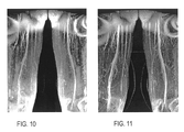
- FIGS. 10 and 11 show a series of SSFP images after being processed using maximum intensity projection (MIP) with 3-D volume acquisitions.
- FIG. 10 shows a MIP from just the SSFP 3-D data set. The soft tissue still appears too bright and obscures adequate visualization of the arterial and venous structures.
- FIG. 11 shows a MIP image that was reconstructed after first subtracting the S ⁇ SSFP data set from the SSFP 3-D data set.
- FIG. 11 shows a marked improvement in both arterial and venous structure visualization.
- the invention includes an MR imaging technique that includes injecting a contrast media bolus into a patient, and then sometime later, applying a pulse sequence with refocusing S ⁇ signals from a train of RF pulses to a desired FOV in the patient.
- the technique includes acquiring an S ⁇ SSFP mask image and an SSFP image of the desired FOV. Either can be acquired first, and by acquiring one right after the other, image mis-registration can be avoided.
- the technique includes subtracting the S ⁇ mask image from the SSFP image.
- the technique includes applying a scale factor to the S ⁇ mask image before subtracting the S ⁇ mask image from the SSFP image.
- a scale factor is applied to the S ⁇ mask image before subtracting the S ⁇ mask image from the SSFP image.
- the technique includes applying a scale factor to the S ⁇ mask image before subtracting the S ⁇ mask image from the SSFP image.
- it is preferred to generate a maximum intensity projection image for best visualization of the venous structure.
- the invention is particularly useful in MR angiography where the desired FOV includes an area having a set of small vessels to screen for venous vascular disease, such as deep venous thrombosis which has been particularly difficult to diagnose in the calf area of a patient.
- the speed of the image acquisition also enables the screening of deep venous thrombus above the knee through the superficial femoral veins, iliac veins, inferior vena cava, right ventricle and pulmonary arteries.
- thrombus into the pulmonary arteries, a.k.a. pulmonary embolism, is the clinical complication of concern for deep venous thrombus as it can be life threatening.
- Another application is for acquisition of a high spatial resolution image subsequent to the conventional MRA acquisition 72 and 76 of FIG. 3 . If the original screen draws attention to a region of possible arterial stenosis, the delayed acquisition can be performed with higher spatial resolution using the above fore-mentioned technique. The degree of stenosis can be better assessed from the high spatial resolution images to improve on the specificity of diagnosis.
- This technique could complement conventional contrast-enhanced MRA as an adjunct for example to increase diagnostic confidence in the detection of potential lesions (i.e. stenosis or intimal pathology) or to serve as an additional option following a non-diagnostic or failed contrast-enhanced MRA that occurs in approximately 10% in clinical cases.
- the acquisition of the S ⁇ mask image can be acquired either before or after the acquisition of the SSFP image and is not dependent on the time elapsed from the injection of the contrast bolus.
- the technique can also include acquiring a second S ⁇ mask image of the desired FOV, and then selecting which of the two, or more, S ⁇ mask images minimizes mis-registration artifacts best, and then subtracting the selected S ⁇ mask image from the SSFP image.
- the present invention can be used with a first pass MRA to create a new hybrid approach. That is, the aforementioned technique can include acquiring an arterial-only mask image before injecting the contrast bolus, and then acquiring an arterial image a desired time after injecting the contrast bolus during a first pass of the contrast bolus but before acquiring the SSFP and the S ⁇ mask images. The arterial-only mask image can then be subtracted from the arterial image to create an MR image of only the arterial structure.
- This technique can be implemented with an MRI such as that described with reference to FIG. 1 .
- the computer of that system is then programmed to acquire an SSFP image and an S ⁇ SSFP image, one after the other, and in either order.
- the computer is programmed to subtract the S ⁇ image from the SSFP image and then reconstruct an image with high contrast from the subtracted images.
- the computer is also programmed to acquire the S ⁇ and SSFP images with minimal time separation therebetween to reduce mis-registration artifacts.
- the computer can optionally be programmed to apply the scaling factor, or allow operator intervention to allow trial and error of various scaling factors.
- the invention is also embodied in a computer program that causes the computer to apply the SSFP pulse sequence and acquire an SSFP image, and apply an S ⁇ pulse sequence and acquire an S ⁇ SSFP image.
- the program then causes the computer to subtract the images and reconstruct an image with high background suppression and significant contrast between blood vessels and other soft tissue, such as fat, muscle, and bone marrow.
- the computer program can also perform the other steps and/or acts previously described.
Landscapes
- Physics & Mathematics (AREA)
- Health & Medical Sciences (AREA)
- General Health & Medical Sciences (AREA)
- Nuclear Medicine, Radiotherapy & Molecular Imaging (AREA)
- Radiology & Medical Imaging (AREA)
- Engineering & Computer Science (AREA)
- Signal Processing (AREA)
- High Energy & Nuclear Physics (AREA)
- Condensed Matter Physics & Semiconductors (AREA)
- General Physics & Mathematics (AREA)
- Magnetic Resonance Imaging Apparatus (AREA)
Priority Applications (4)
| Application Number | Priority Date | Filing Date | Title |
|---|---|---|---|
| US09/681,090 US6493569B2 (en) | 2000-12-30 | 2000-12-30 | Method and apparatus using post contrast-enhanced steady-state free precession in MR imaging |
| EP01310735A EP1223433B1 (en) | 2000-12-30 | 2001-12-20 | Method and apparatus using post contrast-enhanced steady-state free precession in MR imaging |
| DE60124211T DE60124211T2 (de) | 2000-12-30 | 2001-12-20 | Verfahren und Gerät zur Verwendung von freier Präzession im Gleichgewichtszustand nach Kontrastverstärkung in der bildgebenden magnetischen Resonanz |
| JP2001399032A JP3964202B2 (ja) | 2000-12-30 | 2001-12-28 | Mrイメージングにおいて造影強調後の定常自由歳差運動を使用する方法及び装置 |
Applications Claiming Priority (1)
| Application Number | Priority Date | Filing Date | Title |
|---|---|---|---|
| US09/681,090 US6493569B2 (en) | 2000-12-30 | 2000-12-30 | Method and apparatus using post contrast-enhanced steady-state free precession in MR imaging |
Publications (2)
| Publication Number | Publication Date |
|---|---|
| US20020087070A1 US20020087070A1 (en) | 2002-07-04 |
| US6493569B2 true US6493569B2 (en) | 2002-12-10 |
Family
ID=24733777
Family Applications (1)
| Application Number | Title | Priority Date | Filing Date |
|---|---|---|---|
| US09/681,090 Expired - Lifetime US6493569B2 (en) | 2000-12-30 | 2000-12-30 | Method and apparatus using post contrast-enhanced steady-state free precession in MR imaging |
Country Status (4)
| Country | Link |
|---|---|
| US (1) | US6493569B2 (enExample) |
| EP (1) | EP1223433B1 (enExample) |
| JP (1) | JP3964202B2 (enExample) |
| DE (1) | DE60124211T2 (enExample) |
Cited By (35)
| Publication number | Priority date | Publication date | Assignee | Title |
|---|---|---|---|---|
| US20010021263A1 (en) * | 2000-03-08 | 2001-09-13 | Akira Oosawa | Image processing method and system, and storage medium |
| US20020149366A1 (en) * | 2001-04-17 | 2002-10-17 | Ge Yokogawa Medical Systems, Limited | Data collection method and MRI system |
| US20020196019A1 (en) * | 2001-06-21 | 2002-12-26 | Aki Yamazaki | MRI system |
| US6577127B2 (en) * | 2000-03-27 | 2003-06-10 | Koninklijke Philips Electronics N.V. | Magnetic resonance imaging method for imaging time-dependent contrast |
| US20030179944A1 (en) * | 2002-03-20 | 2003-09-25 | Eastman Kodak Company | Calculating noise from multiple digital images having a common noise source |
| US6653834B2 (en) * | 2000-11-14 | 2003-11-25 | Koninklijke Philips Electronics N.V. | Magnetic resonance imaging method |
| US20040004476A1 (en) * | 2002-07-03 | 2004-01-08 | The Board Of Trustees Of The Leland Stanford Junior University | Fat suppression in MRI using oscillating steady-state free precession |
| US20050046644A1 (en) * | 2003-08-28 | 2005-03-03 | Satoru Ohishi | 3D image processing apparatus |
| US20050171422A1 (en) * | 2004-01-09 | 2005-08-04 | Weiguo Zhang | Water fat separated magnetic resonance imaging method and system using steady-state free-precession |
| US20050256393A1 (en) * | 2002-04-08 | 2005-11-17 | Sean Casey Louis Deoni | System and method for generating t1 and t2 maps |
| US20050277828A1 (en) * | 1998-04-13 | 2005-12-15 | The Trustees Of The University Of Pennsylvania | Multi-slice cerebral blood flow imaging with continuous arterial spin labeling MRI |
| US20070103155A1 (en) * | 2005-11-10 | 2007-05-10 | Tsekos Nikolaos V | Method and apparatus for magnetic resonance imaging using directional selective K-space acquisition |
| US20080084208A1 (en) * | 2006-10-06 | 2008-04-10 | Yoshikazu Ikezaki | Magnetic resonance imaging apparatus, magnetic resonance imaging method, scan apparatus, program and storage medium |
| US20080091100A1 (en) * | 2006-09-25 | 2008-04-17 | Stefan Assmann | Method and imaging processing unit and medical imaging device for producing a contrast enhanced image data record of an examination region of a patient |
| US20090028399A1 (en) * | 2007-07-26 | 2009-01-29 | Siemens Medical Solutions Usa, Inc. | System and Method for Detecting Stripe Artifacts in MIP Rendered Images |
| US7545967B1 (en) * | 2002-09-18 | 2009-06-09 | Cornell Research Foundation Inc. | System and method for generating composite subtraction images for magnetic resonance imaging |
| US20100142784A1 (en) * | 2007-05-17 | 2010-06-10 | University Of Washington | Fast two-point mapping of the bound pool fraction and cross-relaxation rate constant for mri |
| US20100160767A1 (en) * | 2008-12-23 | 2010-06-24 | Michael Deimling | Method for contrast-agent-free angiographic imaging in magnetic resonance tomography |
| US20110092797A1 (en) * | 2008-03-18 | 2011-04-21 | University Of Washington | Motion-sensitized driven equilibrium blood-suppression sequence for vessel wall imaging |
| US7941204B1 (en) * | 2004-11-16 | 2011-05-10 | Yi Wang | Magnetic resonance imaging concepts |
| US20110241672A1 (en) * | 2010-04-01 | 2011-10-06 | King Kevin F | Apparatus and method for parallel transmission of rf pulses in a spin echo sequence |
| USRE43749E1 (en) * | 2000-12-27 | 2012-10-16 | Kabushiki Kaisha Toshiba | MRI system and MR imaging method |
| US20130216119A1 (en) * | 2012-02-17 | 2013-08-22 | Siemens Medical Solutions Usa, Inc. | System for Suppressing Vascular Structure in Medical Images |
| US20140241607A1 (en) * | 2009-02-23 | 2014-08-28 | Kabushiki Kaisha Toshiba | Medical image processing apparatus and medical image processing method |
| US10502802B1 (en) | 2010-04-14 | 2019-12-10 | Hypres, Inc. | System and method for noise reduction in magnetic resonance imaging |
| US10828086B2 (en) | 2008-04-29 | 2020-11-10 | Virginia Tech Intellectual Properties, Inc. | Immunotherapeutic methods using irreversible electroporation |
| US11129673B2 (en) | 2017-05-05 | 2021-09-28 | Uptake Medical Technology Inc. | Extra-airway vapor ablation for treating airway constriction in patients with asthma and COPD |
| US11707629B2 (en) | 2009-05-28 | 2023-07-25 | Angiodynamics, Inc. | System and method for synchronizing energy delivery to the cardiac rhythm |
| US11723710B2 (en) | 2016-11-17 | 2023-08-15 | Angiodynamics, Inc. | Techniques for irreversible electroporation using a single-pole tine-style internal device communicating with an external surface electrode |
| US11779395B2 (en) | 2011-09-28 | 2023-10-10 | Angiodynamics, Inc. | Multiple treatment zone ablation probe |
| US11931096B2 (en) | 2010-10-13 | 2024-03-19 | Angiodynamics, Inc. | System and method for electrically ablating tissue of a patient |
| US11957405B2 (en) | 2013-06-13 | 2024-04-16 | Angiodynamics, Inc. | Methods of sterilization and treating infection using irreversible electroporation |
| US12102376B2 (en) | 2012-02-08 | 2024-10-01 | Angiodynamics, Inc. | System and method for increasing a target zone for electrical ablation |
| US12114911B2 (en) | 2014-08-28 | 2024-10-15 | Angiodynamics, Inc. | System and method for ablating a tissue site by electroporation with real-time pulse monitoring |
| US12201349B2 (en) | 2009-04-03 | 2025-01-21 | Angiodynamics, Inc. | Congestive obstruction pulmonary disease (COPD) |
Families Citing this family (14)
| Publication number | Priority date | Publication date | Assignee | Title |
|---|---|---|---|---|
| US6549798B2 (en) | 2001-02-07 | 2003-04-15 | Epix Medical, Inc. | Magnetic resonance angiography data |
| US7715900B2 (en) * | 2002-12-19 | 2010-05-11 | University Of Washington | Quadruple inversion recovery for quantitative contrast-enhanced black blood imaging |
| US7627359B2 (en) * | 2002-12-19 | 2009-12-01 | University Of Washington | Quantitative contrast enhanced black-blood imaging using quadruple-inversion recovery |
| AR047692A1 (es) * | 2003-07-10 | 2006-02-08 | Epix Medical Inc | Imagenes de blancos estacionarios |
| WO2006096499A2 (en) * | 2005-03-04 | 2006-09-14 | Washington University | Mr coronary angiography with a fluorinated nanoparticle contrast agent at 1.5 t |
| JP5037075B2 (ja) * | 2005-12-22 | 2012-09-26 | ジーイー・メディカル・システムズ・グローバル・テクノロジー・カンパニー・エルエルシー | 磁気共鳴イメージング装置 |
| US9538936B2 (en) | 2006-11-22 | 2017-01-10 | Toshiba Medical Systems Corporation | MRI apparatus acquires first and second MR data and generates therefrom third image data having higher contrast between blood and background tissues |
| US10098563B2 (en) | 2006-11-22 | 2018-10-16 | Toshiba Medical Systems Corporation | Magnetic resonance imaging apparatus |
| US7995829B2 (en) * | 2007-08-01 | 2011-08-09 | General Electric Company | Method and apparatus for inspecting components |
| JP5483308B2 (ja) * | 2007-11-21 | 2014-05-07 | 株式会社東芝 | 磁気共鳴イメージング装置 |
| JP5624273B2 (ja) * | 2007-11-22 | 2014-11-12 | 株式会社東芝 | 磁気共鳴イメージング装置 |
| JP5133711B2 (ja) * | 2008-01-10 | 2013-01-30 | ジーイー・メディカル・システムズ・グローバル・テクノロジー・カンパニー・エルエルシー | 磁気共鳴イメージング装置および磁気共鳴画像生成方法 |
| US11199602B2 (en) * | 2019-08-29 | 2021-12-14 | Shanghai United Imaging Intelligence Co., Ltd. | Methods and devices for generating sampling masks related to imaging |
| NL2026047B1 (en) * | 2020-07-10 | 2022-03-15 | Mriguidance B V | Method for generating a magnetic resonance contrast image |
Citations (7)
| Publication number | Priority date | Publication date | Assignee | Title |
|---|---|---|---|---|
| US4973906A (en) * | 1989-08-17 | 1990-11-27 | General Electric Company | Flow compensated NMR fast pulse sequence |
| US5034692A (en) * | 1989-02-24 | 1991-07-23 | Siemens Aktiengesellschaft | Magnetic resonance imaging method for acquiring flux-compensated, T2 -w |
| US5170122A (en) * | 1991-07-25 | 1992-12-08 | General Electric | NMR imaging using flow compensated SSFP pulse sequences |
| US5256967A (en) * | 1992-10-01 | 1993-10-26 | General Electric Company | Fast NMR image acquisition with spectrally selective inversion pulses |
| US5349295A (en) * | 1991-09-25 | 1994-09-20 | Kabushiki Kaisha Toshiba | Magnetic resonance imaging method and apparatus |
| US5437216A (en) * | 1994-05-03 | 1995-08-01 | Leonard Studio Equipment, Inc. | Universal hydraulic valve |
| US6366090B1 (en) * | 1998-12-28 | 2002-04-02 | Siemens Aktiengesellschaft | Magnetic resonance tomography apparatus and operating method allowing multiple scans in rapid succession |
Family Cites Families (2)
| Publication number | Priority date | Publication date | Assignee | Title |
|---|---|---|---|---|
| JPH03268742A (ja) * | 1990-03-19 | 1991-11-29 | Hitachi Ltd | イメージング装置 |
| JPH05184555A (ja) * | 1991-03-20 | 1993-07-27 | Hitachi Ltd | 磁気共鳴イメージング方法及び装置 |
-
2000
- 2000-12-30 US US09/681,090 patent/US6493569B2/en not_active Expired - Lifetime
-
2001
- 2001-12-20 DE DE60124211T patent/DE60124211T2/de not_active Expired - Lifetime
- 2001-12-20 EP EP01310735A patent/EP1223433B1/en not_active Expired - Lifetime
- 2001-12-28 JP JP2001399032A patent/JP3964202B2/ja not_active Expired - Lifetime
Patent Citations (7)
| Publication number | Priority date | Publication date | Assignee | Title |
|---|---|---|---|---|
| US5034692A (en) * | 1989-02-24 | 1991-07-23 | Siemens Aktiengesellschaft | Magnetic resonance imaging method for acquiring flux-compensated, T2 -w |
| US4973906A (en) * | 1989-08-17 | 1990-11-27 | General Electric Company | Flow compensated NMR fast pulse sequence |
| US5170122A (en) * | 1991-07-25 | 1992-12-08 | General Electric | NMR imaging using flow compensated SSFP pulse sequences |
| US5349295A (en) * | 1991-09-25 | 1994-09-20 | Kabushiki Kaisha Toshiba | Magnetic resonance imaging method and apparatus |
| US5256967A (en) * | 1992-10-01 | 1993-10-26 | General Electric Company | Fast NMR image acquisition with spectrally selective inversion pulses |
| US5437216A (en) * | 1994-05-03 | 1995-08-01 | Leonard Studio Equipment, Inc. | Universal hydraulic valve |
| US6366090B1 (en) * | 1998-12-28 | 2002-04-02 | Siemens Aktiengesellschaft | Magnetic resonance tomography apparatus and operating method allowing multiple scans in rapid succession |
Non-Patent Citations (1)
| Title |
|---|
| Zur Y, Wood ML, Neuringer LJ. Motion insensitive SSFP imaging. Magn Reson Med. 1990; 16: 444-59. |
Cited By (57)
| Publication number | Priority date | Publication date | Assignee | Title |
|---|---|---|---|---|
| US20080208033A1 (en) * | 1998-04-13 | 2008-08-28 | The Trustees Of The University Of Pennsylvania | Multi-slice cerebral blood flow imaging with continuous arterial spin labeling mri |
| US6980845B1 (en) * | 1998-04-13 | 2005-12-27 | The Trustees Of The University Of Pennsylvania | Multi-slice cerebral blood flow imaging with continuous arterial spin labeling MRI |
| US20050277828A1 (en) * | 1998-04-13 | 2005-12-15 | The Trustees Of The University Of Pennsylvania | Multi-slice cerebral blood flow imaging with continuous arterial spin labeling MRI |
| US7369888B2 (en) | 1998-04-13 | 2008-05-06 | The Trustees Of The University Of Pennsylvania | Multi-slice cerebral blood flow imaging with continuous arterial spin labeling MRI |
| US7865228B2 (en) | 1998-04-13 | 2011-01-04 | The Trustees Of The University Of Pennsylvania | Multi-slice cerebral blood flow imaging with continuous arterial spin labeling MRI |
| US20010021263A1 (en) * | 2000-03-08 | 2001-09-13 | Akira Oosawa | Image processing method and system, and storage medium |
| US6577127B2 (en) * | 2000-03-27 | 2003-06-10 | Koninklijke Philips Electronics N.V. | Magnetic resonance imaging method for imaging time-dependent contrast |
| US6653834B2 (en) * | 2000-11-14 | 2003-11-25 | Koninklijke Philips Electronics N.V. | Magnetic resonance imaging method |
| USRE43749E1 (en) * | 2000-12-27 | 2012-10-16 | Kabushiki Kaisha Toshiba | MRI system and MR imaging method |
| US6940280B2 (en) * | 2001-04-17 | 2005-09-06 | Ge Medical Systems Global Technology Company, Llc | Systems and methods for manipulating changes in phase encodes |
| US20020149366A1 (en) * | 2001-04-17 | 2002-10-17 | Ge Yokogawa Medical Systems, Limited | Data collection method and MRI system |
| US6819104B2 (en) * | 2001-06-21 | 2004-11-16 | Ge Medical Systems Global Technology Company, Llc | Systems and methods for improving quality of images generated by a medical imaging device |
| US20020196019A1 (en) * | 2001-06-21 | 2002-12-26 | Aki Yamazaki | MRI system |
| US6934421B2 (en) * | 2002-03-20 | 2005-08-23 | Eastman Kodak Company | Calculating noise from multiple digital images having a common noise source |
| US20030179944A1 (en) * | 2002-03-20 | 2003-09-25 | Eastman Kodak Company | Calculating noise from multiple digital images having a common noise source |
| US20050256393A1 (en) * | 2002-04-08 | 2005-11-17 | Sean Casey Louis Deoni | System and method for generating t1 and t2 maps |
| US6750651B2 (en) * | 2002-07-03 | 2004-06-15 | The Board Of Trustees Of The Leland Stanford Junior University | Fat suppression in MRI using oscillating steady-state free precession |
| US20040004476A1 (en) * | 2002-07-03 | 2004-01-08 | The Board Of Trustees Of The Leland Stanford Junior University | Fat suppression in MRI using oscillating steady-state free precession |
| US7545967B1 (en) * | 2002-09-18 | 2009-06-09 | Cornell Research Foundation Inc. | System and method for generating composite subtraction images for magnetic resonance imaging |
| US7734078B2 (en) * | 2002-09-18 | 2010-06-08 | Cornell Research Foundation, Inc. | System and method for generating composite substraction images for magnetic resonance imaging |
| US20090245606A1 (en) * | 2002-09-18 | 2009-10-01 | Cornell Research Foundation, Inc. | System and method for generating composite substraction images for magnetic resonance imaging |
| US20050046644A1 (en) * | 2003-08-28 | 2005-03-03 | Satoru Ohishi | 3D image processing apparatus |
| US7432924B2 (en) * | 2003-08-28 | 2008-10-07 | Kabushiki Kaisha Toshiba | 3D digital subtraction angiography image processing apparatus |
| US7587231B2 (en) | 2004-01-09 | 2009-09-08 | Toshiba America Mri, Inc. | Water fat separated magnetic resonance imaging method and system using steady-state free-precession |
| US20050171422A1 (en) * | 2004-01-09 | 2005-08-04 | Weiguo Zhang | Water fat separated magnetic resonance imaging method and system using steady-state free-precession |
| US11890086B2 (en) | 2004-11-16 | 2024-02-06 | Martin R. Prince | Magnetic resonance imaging concepts |
| US7941204B1 (en) * | 2004-11-16 | 2011-05-10 | Yi Wang | Magnetic resonance imaging concepts |
| US20070103155A1 (en) * | 2005-11-10 | 2007-05-10 | Tsekos Nikolaos V | Method and apparatus for magnetic resonance imaging using directional selective K-space acquisition |
| US20080091100A1 (en) * | 2006-09-25 | 2008-04-17 | Stefan Assmann | Method and imaging processing unit and medical imaging device for producing a contrast enhanced image data record of an examination region of a patient |
| US8077941B2 (en) * | 2006-09-25 | 2011-12-13 | Siemens Aktiengesellschaft | Method and imaging processing unit and medical imaging device for producing a contrast enhanced image data record of an examination region of a patient |
| US7538550B2 (en) | 2006-10-06 | 2009-05-26 | Ge Medical Systems Global Technology Company, Llc | Magnetic resonance imaging apparatus, magnetic resonance imaging method, scan apparatus, program and storage medium |
| US20080084208A1 (en) * | 2006-10-06 | 2008-04-10 | Yoshikazu Ikezaki | Magnetic resonance imaging apparatus, magnetic resonance imaging method, scan apparatus, program and storage medium |
| US20100142784A1 (en) * | 2007-05-17 | 2010-06-10 | University Of Washington | Fast two-point mapping of the bound pool fraction and cross-relaxation rate constant for mri |
| US8369599B2 (en) | 2007-05-17 | 2013-02-05 | University Of Washington | Fast two-point mapping of the bound pool fraction and cross-relaxation rate constant for MRI |
| US20090028399A1 (en) * | 2007-07-26 | 2009-01-29 | Siemens Medical Solutions Usa, Inc. | System and Method for Detecting Stripe Artifacts in MIP Rendered Images |
| US7965879B2 (en) * | 2007-07-26 | 2011-06-21 | Siemens Medical Solutions Usa, Inc. | System and method for detecting stripe artifacts in MIP rendered images |
| US20110092797A1 (en) * | 2008-03-18 | 2011-04-21 | University Of Washington | Motion-sensitized driven equilibrium blood-suppression sequence for vessel wall imaging |
| US9448296B2 (en) | 2008-03-18 | 2016-09-20 | University Of Washington | Motion-sensitized driven equilibrium blood-suppression sequence for vessel wall imaging |
| US10828086B2 (en) | 2008-04-29 | 2020-11-10 | Virginia Tech Intellectual Properties, Inc. | Immunotherapeutic methods using irreversible electroporation |
| US20100160767A1 (en) * | 2008-12-23 | 2010-06-24 | Michael Deimling | Method for contrast-agent-free angiographic imaging in magnetic resonance tomography |
| US8571631B2 (en) | 2008-12-23 | 2013-10-29 | Siemens Aktiengesellschaft | Method for contrast-agent-free angiographic imaging in magnetic resonance tomography |
| US20140241607A1 (en) * | 2009-02-23 | 2014-08-28 | Kabushiki Kaisha Toshiba | Medical image processing apparatus and medical image processing method |
| US9330481B2 (en) * | 2009-02-23 | 2016-05-03 | Kabushiki Kaisha Toshiba | Medical image processing apparatus and medical image processing method |
| US12201349B2 (en) | 2009-04-03 | 2025-01-21 | Angiodynamics, Inc. | Congestive obstruction pulmonary disease (COPD) |
| US11707629B2 (en) | 2009-05-28 | 2023-07-25 | Angiodynamics, Inc. | System and method for synchronizing energy delivery to the cardiac rhythm |
| US8482281B2 (en) * | 2010-04-01 | 2013-07-09 | General Electric Company | Apparatus and method for parallel transmission of RF pulses in a spin echo sequence |
| US20110241672A1 (en) * | 2010-04-01 | 2011-10-06 | King Kevin F | Apparatus and method for parallel transmission of rf pulses in a spin echo sequence |
| US10502802B1 (en) | 2010-04-14 | 2019-12-10 | Hypres, Inc. | System and method for noise reduction in magnetic resonance imaging |
| US11931096B2 (en) | 2010-10-13 | 2024-03-19 | Angiodynamics, Inc. | System and method for electrically ablating tissue of a patient |
| US11779395B2 (en) | 2011-09-28 | 2023-10-10 | Angiodynamics, Inc. | Multiple treatment zone ablation probe |
| US12102376B2 (en) | 2012-02-08 | 2024-10-01 | Angiodynamics, Inc. | System and method for increasing a target zone for electrical ablation |
| US8848996B2 (en) * | 2012-02-17 | 2014-09-30 | Siemens Medical Solutions Usa, Inc. | System for suppressing vascular structure in medical images |
| US20130216119A1 (en) * | 2012-02-17 | 2013-08-22 | Siemens Medical Solutions Usa, Inc. | System for Suppressing Vascular Structure in Medical Images |
| US11957405B2 (en) | 2013-06-13 | 2024-04-16 | Angiodynamics, Inc. | Methods of sterilization and treating infection using irreversible electroporation |
| US12114911B2 (en) | 2014-08-28 | 2024-10-15 | Angiodynamics, Inc. | System and method for ablating a tissue site by electroporation with real-time pulse monitoring |
| US11723710B2 (en) | 2016-11-17 | 2023-08-15 | Angiodynamics, Inc. | Techniques for irreversible electroporation using a single-pole tine-style internal device communicating with an external surface electrode |
| US11129673B2 (en) | 2017-05-05 | 2021-09-28 | Uptake Medical Technology Inc. | Extra-airway vapor ablation for treating airway constriction in patients with asthma and COPD |
Also Published As
| Publication number | Publication date |
|---|---|
| DE60124211D1 (de) | 2006-12-14 |
| US20020087070A1 (en) | 2002-07-04 |
| EP1223433B1 (en) | 2006-11-02 |
| JP2002263082A (ja) | 2002-09-17 |
| DE60124211T2 (de) | 2007-09-06 |
| JP3964202B2 (ja) | 2007-08-22 |
| EP1223433A3 (en) | 2004-08-25 |
| EP1223433A2 (en) | 2002-07-17 |
Similar Documents
| Publication | Publication Date | Title |
|---|---|---|
| US6493569B2 (en) | Method and apparatus using post contrast-enhanced steady-state free precession in MR imaging | |
| US6556856B1 (en) | Dual resolution acquisition of magnetic resonance angiography data with vessel segmentation | |
| CA2315372C (en) | Method for performing magnetic resonance angiography with dynamic k-space sampling | |
| EP0798566B1 (en) | Three-dimensional digital subtraction magnetic resonance angiography | |
| EP1430327B1 (en) | Magnetic resonance angiography using floating table projection imaging | |
| US5928148A (en) | Method for performing magnetic resonance angiography over a large field of view using table stepping | |
| US6381486B1 (en) | Magnetic resonance angiography with vessel segmentation | |
| EP1269212B1 (en) | Magnetic resonance angiography with automated vessel segmentation | |
| US5873825A (en) | Three dimensional digital subtraction magnetic resonance angiography with limited k-space mask | |
| US20110137146A1 (en) | Method for Non-Contrast Enhanced Magnetic Resonance Angiography | |
| US20150157238A1 (en) | Method For Non-Contrast Enhanced Magnetic Resonance Angiography | |
| WO2002059633A1 (en) | Magnetic resonance angiography using undersampled 3d projection imaging | |
| EP1010016A1 (en) | Gated time-resolved contrast-enhanced 3d mr angiography | |
| US5827187A (en) | Dynamic MR digital subtraction angiography with complex subtraction | |
| EP1221623A2 (en) | Method for optimal imaging of the peripheral vasculature emphasizing distal arterial visualization in a multi-station examination | |
| US8760161B2 (en) | System and method for enhanced contrast MR imaging | |
| US8154287B2 (en) | System and method for ghost magnetic resonance imaging | |
| US9968276B2 (en) | System and method for imaging of the vascular components with temporal information and suppressed blood pools using magnetic resonance imaging | |
| US20030158476A1 (en) | Method and apparatus for magnetic resonance imaging using contrast agent | |
| US6259940B1 (en) | Method of performing magnetic resonance angiography using two-dimensional imaging and de-rated gradients | |
| JP2006519677A (ja) | 連続的テーブル移動を用いて時間分解mr画像を取得する方法 | |
| US20130281831A1 (en) | System and method for improved accelerated magnetic resonance imaging using roi masking | |
| US20110166436A1 (en) | System and Method For Non-Contrast MR Angiography Using Steady-State Image Acquisition | |
| JP2006223869A (ja) | 連続的テーブル移動により取得された磁気共鳴画像におけるアーチファクトの除去方法 | |
| US20020133070A1 (en) | Method for performing magnetic resonance angiography with subtraction of projection images |
Legal Events
| Date | Code | Title | Description |
|---|---|---|---|
| AS | Assignment |
Owner name: GE MEDICAL SYSTEMS GLOBAL TECHNOLOGY COMPANY, LLC, Free format text: ASSIGNMENT OF ASSIGNORS INTEREST;ASSIGNOR:FOO, THOMAS K.F.;REEL/FRAME:011480/0014 Effective date: 20001222 Owner name: UNIFORMED SERVICES UNIVERSITY OF HEALTH SCIENCES, Free format text: ASSIGNMENT OF ASSIGNORS INTEREST;ASSIGNOR:HO, VINCENT B.;REEL/FRAME:011477/0890 Effective date: 20001222 |
|
| STCF | Information on status: patent grant |
Free format text: PATENTED CASE |
|
| CC | Certificate of correction | ||
| FPAY | Fee payment |
Year of fee payment: 4 |
|
| FEPP | Fee payment procedure |
Free format text: PAYOR NUMBER ASSIGNED (ORIGINAL EVENT CODE: ASPN); ENTITY STATUS OF PATENT OWNER: LARGE ENTITY Free format text: PAYER NUMBER DE-ASSIGNED (ORIGINAL EVENT CODE: RMPN); ENTITY STATUS OF PATENT OWNER: LARGE ENTITY |
|
| FPAY | Fee payment |
Year of fee payment: 8 |
|
| FPAY | Fee payment |
Year of fee payment: 12 |