US6439292B1 - Rolling door with a flexible door leaf - Google Patents
Rolling door with a flexible door leaf Download PDFInfo
- Publication number
- US6439292B1 US6439292B1 US09/509,160 US50916000A US6439292B1 US 6439292 B1 US6439292 B1 US 6439292B1 US 50916000 A US50916000 A US 50916000A US 6439292 B1 US6439292 B1 US 6439292B1
- Authority
- US
- United States
- Prior art keywords
- blocks
- stop rail
- door
- slide
- stop
- Prior art date
- Legal status (The legal status is an assumption and is not a legal conclusion. Google has not performed a legal analysis and makes no representation as to the accuracy of the status listed.)
- Expired - Lifetime
Links
- 238000005096 rolling process Methods 0.000 title claims abstract description 27
- 238000004804 winding Methods 0.000 claims abstract description 10
- 230000004888 barrier function Effects 0.000 claims description 15
- 230000000717 retained effect Effects 0.000 claims description 4
- 230000000694 effects Effects 0.000 claims description 3
- 230000006835 compression Effects 0.000 claims description 2
- 238000007906 compression Methods 0.000 claims description 2
- 230000005484 gravity Effects 0.000 claims description 2
- 230000008878 coupling Effects 0.000 claims 1
- 238000010168 coupling process Methods 0.000 claims 1
- 238000005859 coupling reaction Methods 0.000 claims 1
- 230000003116 impacting effect Effects 0.000 claims 1
- 239000002184 metal Substances 0.000 claims 1
- 208000027418 Wounds and injury Diseases 0.000 description 3
- 230000006378 damage Effects 0.000 description 3
- 230000001939 inductive effect Effects 0.000 description 1
- 208000014674 injury Diseases 0.000 description 1
Images


Classifications
-
- E—FIXED CONSTRUCTIONS
- E06—DOORS, WINDOWS, SHUTTERS, OR ROLLER BLINDS IN GENERAL; LADDERS
- E06B—FIXED OR MOVABLE CLOSURES FOR OPENINGS IN BUILDINGS, VEHICLES, FENCES OR LIKE ENCLOSURES IN GENERAL, e.g. DOORS, WINDOWS, BLINDS, GATES
- E06B9/00—Screening or protective devices for wall or similar openings, with or without operating or securing mechanisms; Closures of similar construction
- E06B9/02—Shutters, movable grilles, or other safety closing devices, e.g. against burglary
- E06B9/08—Roll-type closures
- E06B9/11—Roller shutters
- E06B9/13—Roller shutters with closing members of one piece, e.g. of corrugated sheet metal
-
- E—FIXED CONSTRUCTIONS
- E06—DOORS, WINDOWS, SHUTTERS, OR ROLLER BLINDS IN GENERAL; LADDERS
- E06B—FIXED OR MOVABLE CLOSURES FOR OPENINGS IN BUILDINGS, VEHICLES, FENCES OR LIKE ENCLOSURES IN GENERAL, e.g. DOORS, WINDOWS, BLINDS, GATES
- E06B9/00—Screening or protective devices for wall or similar openings, with or without operating or securing mechanisms; Closures of similar construction
- E06B9/56—Operating, guiding or securing devices or arrangements for roll-type closures; Spring drums; Tape drums; Counterweighting arrangements therefor
- E06B9/58—Guiding devices
- E06B9/581—Means to prevent or induce disengagement of shutter from side rails
-
- E—FIXED CONSTRUCTIONS
- E06—DOORS, WINDOWS, SHUTTERS, OR ROLLER BLINDS IN GENERAL; LADDERS
- E06B—FIXED OR MOVABLE CLOSURES FOR OPENINGS IN BUILDINGS, VEHICLES, FENCES OR LIKE ENCLOSURES IN GENERAL, e.g. DOORS, WINDOWS, BLINDS, GATES
- E06B9/00—Screening or protective devices for wall or similar openings, with or without operating or securing mechanisms; Closures of similar construction
- E06B9/56—Operating, guiding or securing devices or arrangements for roll-type closures; Spring drums; Tape drums; Counterweighting arrangements therefor
- E06B9/58—Guiding devices
- E06B2009/585—Emergency release to prevent damage of shutter or guiding device
Definitions
- a rolling door with a flexible door panel which can be wound up on a winding shaft pivoted above the door aperture and provided with a drive, having a stop rail fixed to the bottom end of the door panel whose length is less than the clear span between the side sections limiting the door aperture and which is provided at both ends with fastenings for wires running over rollers supported in the ground area and bracing the door panel and having slide-like blocks guided vertically movably in the side sections, which blocks are detachably connected to the ends of the rails by retaining means and are provided with channels or breakthroughs for the wires running from the pulleys on the ground side to the stop rail.
- the retaining means consisting of locking devices which release the stop rail in the event of forces acting thereon from the side and which, when the blocks are pressed on from above, again interlock with them.
- the triggering of the stop rail that is its release from the blocks, is performed in the same way as with the known rolling door.
- the interlock can be effected by exerting pressure onto the stop section from above. It may also be additionally necessary after the snapping in of the interlock connection to align the stop section manually to the blocks and to press the side edges of the door panel into the side slots of the side door sections.
- ratchet levers are pivoted on the blocks around axes running horizontally and diagonally to the plane of the door panel which ratchet levers are biased by springs towards the door panel and which are supported on these on interlock projections of the stop section below the fastenings of the wires.
- the interlock projections can be provided with chamfers on their bottom sides. The ratchets then slip over these chamfers until they snap into their interlocked position behind the interlock projections.
- a sensor for example an inductive proximity switch, which generates signals when the stop section is pushed off at least one of the blocks and when the interlock connection is reinstated between the blocks and the stop section.
- arms or slide elements are slidably guided which have a light barrier on their lower ends which, when it responds, causes a brake to engage which stops the closing movement of the door panel or which switches over the drive of the door panel to the winding up direction.
- the safety device consisting of the slidable arms with a light barrier which brings the stop section to a stop with great security within a stopping length which excludes any injury to persons and/or damage to objects is known per se from EP 0 284 066 B2.
- the arms having the light barrier are slidably guided in guides of the stop section or the lateral sword-like protrusions, which guides are parallel to the side sections.
- the slide elements or arms with the light barrier which are generally designed in the same way as those described in EP 0 284 066 B2, are slidably guided in guides of the blocks so that current can be supplied to the light barriers simply, for example by means of trailing cables.
- the invention further provides the additional advantage of the wires providing the bracing of the stop section not being directly connected to the slide-like blocks guided in the vertical slots of the side stop sections of the door, but rather the blocks being provided with obliquely running breakthroughs or channels through which the wires are guided to their fastenings or fastening pieces on the stop sections.
- the blocks are provided with the obliquely running guides for the bracing wires, after a crash detaching the stop section from the blocks, the blocks can only slide downwards under the effect of gravity until they are stoppingly supported on the bracing wires running obliquely from the pulleys on the ground side to the fastening points on the stop section.
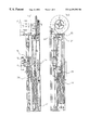
- FIG. 1 shows a longitudinal section through a rolling door in the region of the right door section parallel to the plane of the door panel
- FIG. 2 shows a longitudinal section through the side section of FIG. 1;
- FIG. 3 shows an enlarged section of FIG. 1
- FIG. 4 shows a horizontal section through the section of FIG. 1 .
- a slide-like block 5 made of plastic is guided longitudinally slidably in vertical longitudinal slots of the door section which are parallel to each other and which are formed in the manner visible from FIG. 4 between the section parts 1 , 2 and 3 , 4 .
- a front part 6 being essentially rectangular of the slide-like block 5 penetrates the longitudinal gap limited by the profile parts 1 , 2 towards the door centre.
- a ratchet 8 is pivoted on this projection 6 around a lateral axis 7 which ratchet 8 consists of a sheetmetal part bent into a U shape whose legs 9 enclose the projection 6 -and are provided with bearing boreholes with which these are pivoted on the axle bolt 7 held in the projection 6 .
- the bridge part 10 of the ratchet 8 which bridge part connects the legs, possesses a front support edge 11 .
- the projection 6 is provided with an obliquely running blind hole 12 in which a compression spring 13 is held which is supported with its one end on the bottom of the blind hole 12 and with its other end on the bridge part 10 of the ratchet.
- the flexible door panel (not shown) which can be wound up on the winding shaft 15 usually carries on its bottom end the stop section 16 .
- This stop section is provided on both sides with a retaining part 17 pointing at right angles to the side door sections which is provided with a borehole in which the bracing wire 18 is held by a knot 19 supported on the upper edge of the borehole.
- the bracing wire 18 penetrates the slide-like blocks 5 in guides formed by obliquely running boreholes 20 .
- the bracing wires run from these guides to pulleys 21 supported on the ground in a fixed manner.
- the bracing wires are edged into line in the manner of a set of pulleys between further pulleys 22 to 25 , with the pulley 25 being the pulley of a lower block biased by the tension spring 26 .
- the stop section 16 is provided with side fittings 28 which possess lower interlock projections 29 cantilevered parallel to the retaining parts 17 .
- the interlock projections 29 are provided with top interlock surfaces 30 parallel to the support edges 11 of the ratchets 8 .
- the interlock projections 29 possess oblique abutting surfaces 3 1 .
- the door is visible in a position in which the stop section 16 is interlocked by the ratchet 8 with the slide blocks 5 , that is it is located in its operating position. If, in the event of a crash, which is given, for example, when a vehicle pushes against the stop section, the stop section 16 is pushed off one of the slide blocks 5 , the stop section can swing out freely with the bracing ropes 18 being pulled out. In this situation, the interlock ratchet 8 swings out into the position 10 shown by a broken line in FIG. 3 .
- the bracing wires 18 again pull the stop section 16 in the direction of the slide blocks 5 so that the oblique bottom edge of the interlock projections 28 slides over the bridge parts 10 of the interlock ratchets until the lower support edge 11 of the interlock ratchet snaps into place behind the abutment surface 30 .
- the support edge 11 can be designed with a slight curve or concavely to allow engagement of the interlock projection 29 in a well centred manner.
- the slide blocks 5 are provided with parallel boreholes on the door section in which arms 35 are guided longitudinally slidably.
- the arms 35 have on their lower ends light barriers 36 which cause the brake of the gear brake motor to engage which drives the winding shaft 15 in a manner not shown when the light barrier reports that a person or an object is located in the closing path of the stop section.
- the type of guide of the arm 35 in the slide block 5 and the effect of the light barrier 36 is known from EP 0 284 066 B2 to which reference is made for a closer description of the safety device.
- a detaching of the interlock connection is performed in a manner such that the stop section 16 of the door panel is pushed off the protrusion 6 of the slide block 5 , the slide block 5 with the arm 35 which has the light barrier 36 slides so far down until the slide block 5 is held in its oblique boring hole on the obliquely running bracing wire 18 .
- the door panel is travelled into its closing position by its drive until the slide blocks 5 impact the floor and the arms 35 are pushed upwards in the guides. In this position, the bracing wires 18 pull the stop section against the slide blocks 5 so that the interlock connection is restored between the two and the door is put back into its operating status.
Landscapes
- Engineering & Computer Science (AREA)
- Structural Engineering (AREA)
- Architecture (AREA)
- Civil Engineering (AREA)
- Gates (AREA)
- Power-Operated Mechanisms For Wings (AREA)
- Operating, Guiding And Securing Of Roll- Type Closing Members (AREA)
- Closing And Opening Devices For Wings, And Checks For Wings (AREA)
- Support Devices For Sliding Doors (AREA)
- Special Wing (AREA)
Abstract
Description
Claims (14)
Applications Claiming Priority (3)
| Application Number | Priority Date | Filing Date | Title |
|---|---|---|---|
| DE29716966U | 1997-09-22 | ||
| DE29716966U DE29716966U1 (en) | 1997-09-22 | 1997-09-22 | Roller door with a flexible door leaf |
| PCT/EP1998/005566 WO1999015754A1 (en) | 1997-09-22 | 1998-09-02 | Rolling door with a flexible door leaf |
Publications (1)
| Publication Number | Publication Date |
|---|---|
| US6439292B1 true US6439292B1 (en) | 2002-08-27 |
Family
ID=8046324
Family Applications (1)
| Application Number | Title | Priority Date | Filing Date |
|---|---|---|---|
| US09/509,160 Expired - Lifetime US6439292B1 (en) | 1997-09-22 | 1998-09-02 | Rolling door with a flexible door leaf |
Country Status (13)
| Country | Link |
|---|---|
| US (1) | US6439292B1 (en) |
| JP (1) | JP4286449B2 (en) |
| KR (1) | KR100576632B1 (en) |
| AR (1) | AR017058A1 (en) |
| AU (1) | AU736907B2 (en) |
| BR (1) | BR9812355A (en) |
| CA (1) | CA2303116C (en) |
| DE (2) | DE29716966U1 (en) |
| DK (1) | DK174775B1 (en) |
| MX (1) | MXPA00002831A (en) |
| PL (1) | PL339167A1 (en) |
| SE (1) | SE0000958L (en) |
| WO (1) | WO1999015754A1 (en) |
Cited By (12)
| Publication number | Priority date | Publication date | Assignee | Title |
|---|---|---|---|---|
| US20030046870A1 (en) * | 1999-04-14 | 2003-03-13 | Guido Langenbach | Crash protection device |
| US6688374B2 (en) * | 2001-11-09 | 2004-02-10 | Rite-Hite Holding Corporation | Barrier with movable curtain |
| US20050247412A1 (en) * | 2004-05-04 | 2005-11-10 | Mikael Bengtsson | High load operation of an industrial roll door |
| US20070277942A1 (en) * | 2006-06-05 | 2007-12-06 | Jason Dondlinger | Track and guide system for a door |
| US20070277941A1 (en) * | 2006-06-05 | 2007-12-06 | Rite-Hite Holding Corporation | Track and guide system for a door |
| US20070277943A1 (en) * | 2006-06-05 | 2007-12-06 | Rite-Hite Holding Corporation | Track and guide system for a door |
| US20090229769A1 (en) * | 2008-03-12 | 2009-09-17 | Lutron Electronics Co., Inc. | Self-Contained Tensioned Roller Shade System |
| US20090229770A1 (en) * | 2008-03-12 | 2009-09-17 | Lutron Electronics Co., Inc. | Tensioned Roller Shade System Having a Conical, Grooved Spool |
| US20110073262A1 (en) * | 2009-09-25 | 2011-03-31 | Friedhelm Frede | Adjustable counterbalance system for roller doors |
| US20150337594A1 (en) * | 2012-11-29 | 2015-11-26 | Efaflex Inzeniring D.O.O. Ljubljana | Rolling Gate Having a Door Leaf in the Form of a Flexible Curtain |
| CN109113551A (en) * | 2018-10-31 | 2019-01-01 | 李健志 | Turnover device and slotless rolling screen door comprising it |
| US10208536B2 (en) * | 2013-06-28 | 2019-02-19 | Screenaway Pty Ltd | Screen system |
Families Citing this family (6)
| Publication number | Priority date | Publication date | Assignee | Title |
|---|---|---|---|---|
| DE19949329C2 (en) * | 1999-10-13 | 2002-10-02 | Seuster Adolf Gmbh & Co Kg | speed door |
| DE10052967B4 (en) * | 2000-10-25 | 2005-11-10 | Guido Langenbach | Chrash protection device for high-speed roller doors |
| DE10339506B4 (en) * | 2003-08-27 | 2005-12-15 | Frank Dittmer | lifting door |
| DE102004014350B4 (en) * | 2003-08-27 | 2007-04-12 | Frank Dittmer | lifting door |
| DE202010007949U1 (en) * | 2010-06-30 | 2010-09-02 | Efaflex Tortechnik Gmbh | rolling gate |
| KR102496370B1 (en) | 2016-03-07 | 2023-02-06 | 삼성전자주식회사 | Rail device and refrigerator having the smae |
Citations (13)
| Publication number | Priority date | Publication date | Assignee | Title |
|---|---|---|---|---|
| DE3709592A1 (en) | 1987-03-24 | 1988-10-13 | Schieffer Gmbh Co Kg | QUICK OPEN DOOR |
| US4953608A (en) * | 1986-10-09 | 1990-09-04 | Nomafa Ab | Safety device, particularly for roll-up doors |
| US4974658A (en) * | 1989-02-22 | 1990-12-04 | Komatsu Denki Sangyo Kabushiki Kaisha | Sheet shutter |
| US5025847A (en) | 1989-06-27 | 1991-06-25 | Rytec Corporation | Apparatus for accommodating application of a force in excess of a predetermined magnitude and closure employing such apparatus |
| DE4007280A1 (en) | 1990-02-12 | 1991-08-14 | Norbert Lamsfuss | Overload protection for flexible door - consists of bar with lugs which bend or break under excessive load |
| US5353859A (en) * | 1992-09-14 | 1994-10-11 | Rite-Hite Corporation | Roller door apparatus |
| DE4313062A1 (en) | 1993-04-21 | 1994-10-27 | Efaflex Transport Lager | Rolling shutter door with control device |
| EP0675261A1 (en) | 1994-03-28 | 1995-10-04 | Schieffer GmbH & Co Kommanditgesellschaft | Roller door with flexible door leaf |
| DE4414524A1 (en) | 1994-03-28 | 1995-10-05 | Schieffer Gmbh Co Kg | Roller door with a flexible door leaf |
| US5601133A (en) * | 1995-03-31 | 1997-02-11 | Overhead Door Corporation | Roll-up door |
| US5620039A (en) | 1995-02-10 | 1997-04-15 | Rytec Corporation | Apparatus for providing a slidingly-separable connection between a movable barrier and a means for guiding the barrier |
| US5638883A (en) | 1995-02-10 | 1997-06-17 | Rite-Hite Corporation | Breakaway guide assembly for a roller door |
| US6082433A (en) * | 1997-11-21 | 2000-07-04 | Overhead Door Corporation | Control system and method for roll-up door |
-
1997
- 1997-09-22 DE DE29716966U patent/DE29716966U1/en not_active Expired - Lifetime
-
1998
- 1998-09-02 PL PL98339167A patent/PL339167A1/en unknown
- 1998-09-02 DE DE19881378T patent/DE19881378D2/en not_active Ceased
- 1998-09-02 AU AU95356/98A patent/AU736907B2/en not_active Expired
- 1998-09-02 KR KR1020007002948A patent/KR100576632B1/en not_active Expired - Lifetime
- 1998-09-02 MX MXPA00002831A patent/MXPA00002831A/en active IP Right Grant
- 1998-09-02 BR BR9812355-6A patent/BR9812355A/en not_active IP Right Cessation
- 1998-09-02 CA CA002303116A patent/CA2303116C/en not_active Expired - Lifetime
- 1998-09-02 JP JP2000513034A patent/JP4286449B2/en not_active Expired - Lifetime
- 1998-09-02 US US09/509,160 patent/US6439292B1/en not_active Expired - Lifetime
- 1998-09-02 WO PCT/EP1998/005566 patent/WO1999015754A1/en not_active Ceased
- 1998-09-04 AR ARP980104426A patent/AR017058A1/en active IP Right Grant
-
2000
- 2000-03-16 DK DK200000430A patent/DK174775B1/en not_active IP Right Cessation
- 2000-03-21 SE SE0000958A patent/SE0000958L/en unknown
Patent Citations (14)
| Publication number | Priority date | Publication date | Assignee | Title |
|---|---|---|---|---|
| US4953608A (en) * | 1986-10-09 | 1990-09-04 | Nomafa Ab | Safety device, particularly for roll-up doors |
| DE3709592A1 (en) | 1987-03-24 | 1988-10-13 | Schieffer Gmbh Co Kg | QUICK OPEN DOOR |
| US4974658A (en) * | 1989-02-22 | 1990-12-04 | Komatsu Denki Sangyo Kabushiki Kaisha | Sheet shutter |
| US5025847A (en) | 1989-06-27 | 1991-06-25 | Rytec Corporation | Apparatus for accommodating application of a force in excess of a predetermined magnitude and closure employing such apparatus |
| DE4007280A1 (en) | 1990-02-12 | 1991-08-14 | Norbert Lamsfuss | Overload protection for flexible door - consists of bar with lugs which bend or break under excessive load |
| US5353859A (en) * | 1992-09-14 | 1994-10-11 | Rite-Hite Corporation | Roller door apparatus |
| DE4313062A1 (en) | 1993-04-21 | 1994-10-27 | Efaflex Transport Lager | Rolling shutter door with control device |
| EP0675261A1 (en) | 1994-03-28 | 1995-10-04 | Schieffer GmbH & Co Kommanditgesellschaft | Roller door with flexible door leaf |
| DE4414524A1 (en) | 1994-03-28 | 1995-10-05 | Schieffer Gmbh Co Kg | Roller door with a flexible door leaf |
| DE4447598C1 (en) | 1994-03-28 | 1997-03-06 | Schieffer Gmbh Co Kg | Roller door with flexible panel |
| US5620039A (en) | 1995-02-10 | 1997-04-15 | Rytec Corporation | Apparatus for providing a slidingly-separable connection between a movable barrier and a means for guiding the barrier |
| US5638883A (en) | 1995-02-10 | 1997-06-17 | Rite-Hite Corporation | Breakaway guide assembly for a roller door |
| US5601133A (en) * | 1995-03-31 | 1997-02-11 | Overhead Door Corporation | Roll-up door |
| US6082433A (en) * | 1997-11-21 | 2000-07-04 | Overhead Door Corporation | Control system and method for roll-up door |
Cited By (33)
| Publication number | Priority date | Publication date | Assignee | Title |
|---|---|---|---|---|
| US20030046870A1 (en) * | 1999-04-14 | 2003-03-13 | Guido Langenbach | Crash protection device |
| US6901703B2 (en) | 1999-04-14 | 2005-06-07 | Rite-Hite Holding Corporation | Crash protection device |
| US6688374B2 (en) * | 2001-11-09 | 2004-02-10 | Rite-Hite Holding Corporation | Barrier with movable curtain |
| AU2010200340B2 (en) * | 2004-05-04 | 2011-07-28 | Assa Abloy Entrance Systems Ab | High load operation of an industrial roll door |
| WO2005108732A3 (en) * | 2004-05-04 | 2006-05-26 | Albany Int Corp | High load operation of an industrial roll door |
| US7252133B2 (en) * | 2004-05-04 | 2007-08-07 | Albany International Corp. | High load operation of an industrial roll door |
| CN102140882B (en) * | 2004-05-04 | 2012-10-10 | 阿尔巴尼国际公司 | High load operation of an industrial roll door |
| EP2458130A1 (en) | 2004-05-04 | 2012-05-30 | Albany International Corp. | High load operation of an industrial roll door |
| US8162028B2 (en) | 2004-05-04 | 2012-04-24 | Assa Abloy Entrance Systems Ab | High load operation of an industrial roll door |
| US20080041536A1 (en) * | 2004-05-04 | 2008-02-21 | Mikael Bengtsson | High Load Operation of an Industrial Roll Door |
| CN1950584B (en) * | 2004-05-04 | 2011-04-13 | 阿尔巴尼国际公司 | Shutter doors |
| US20050247412A1 (en) * | 2004-05-04 | 2005-11-10 | Mikael Bengtsson | High load operation of an industrial roll door |
| RU2372465C2 (en) * | 2004-05-04 | 2009-11-10 | Олбани Интернешнл Корп. | Roll door used in industry for operation under higher load |
| US20100263286A1 (en) * | 2006-06-05 | 2010-10-21 | Tom Jansen | Track and guide system for a door |
| US7748431B2 (en) | 2006-06-05 | 2010-07-06 | Rite-Hite Holding Corporation | Track and guide system for a door |
| US20110067307A1 (en) * | 2006-06-05 | 2011-03-24 | Jason Dondlinger | Track and guide system for a door |
| US8857498B2 (en) | 2006-06-05 | 2014-10-14 | Rite-Hite Holding Corporation | Track and guide system for a door |
| US8037921B2 (en) | 2006-06-05 | 2011-10-18 | Rite-Hite Holding Corporation | Track and guide system for a door |
| US20070277943A1 (en) * | 2006-06-05 | 2007-12-06 | Rite-Hite Holding Corporation | Track and guide system for a door |
| US20070277941A1 (en) * | 2006-06-05 | 2007-12-06 | Rite-Hite Holding Corporation | Track and guide system for a door |
| US8863815B2 (en) | 2006-06-05 | 2014-10-21 | Rite-Hite Holding Corporation | Track and guide system for a door |
| US20070277942A1 (en) * | 2006-06-05 | 2007-12-06 | Jason Dondlinger | Track and guide system for a door |
| US20090229770A1 (en) * | 2008-03-12 | 2009-09-17 | Lutron Electronics Co., Inc. | Tensioned Roller Shade System Having a Conical, Grooved Spool |
| US20090229769A1 (en) * | 2008-03-12 | 2009-09-17 | Lutron Electronics Co., Inc. | Self-Contained Tensioned Roller Shade System |
| US8056601B2 (en) * | 2008-03-12 | 2011-11-15 | Lutron Electronics Co., Inc. | Self-contained tensioned roller shade system |
| US8113264B2 (en) * | 2008-03-12 | 2012-02-14 | Lutron Electronics Co., Inc. | Tensioned roller shade system having a conical, grooved spool |
| US20110073262A1 (en) * | 2009-09-25 | 2011-03-31 | Friedhelm Frede | Adjustable counterbalance system for roller doors |
| US8267146B2 (en) | 2009-09-25 | 2012-09-18 | Assa Abloy Entrance Systems Ab | Adjustable counterbalance system for roller doors |
| US20150337594A1 (en) * | 2012-11-29 | 2015-11-26 | Efaflex Inzeniring D.O.O. Ljubljana | Rolling Gate Having a Door Leaf in the Form of a Flexible Curtain |
| US9840869B2 (en) * | 2012-11-29 | 2017-12-12 | Efaflex Inzeniring D.O.O. Ljubljana | Rolling gate having a door leaf in the form of a flexible curtain |
| US10208536B2 (en) * | 2013-06-28 | 2019-02-19 | Screenaway Pty Ltd | Screen system |
| CN109113551A (en) * | 2018-10-31 | 2019-01-01 | 李健志 | Turnover device and slotless rolling screen door comprising it |
| CN109113551B (en) * | 2018-10-31 | 2023-11-21 | 李健志 | Turning device and contain its slotless rolling slats door |
Also Published As
| Publication number | Publication date |
|---|---|
| DE29716966U1 (en) | 1997-11-13 |
| KR20010040246A (en) | 2001-05-15 |
| CA2303116A1 (en) | 1999-04-01 |
| JP4286449B2 (en) | 2009-07-01 |
| JP2001517750A (en) | 2001-10-09 |
| SE0000958D0 (en) | 2000-03-21 |
| AR017058A1 (en) | 2001-08-22 |
| DE19881378D2 (en) | 2000-11-30 |
| SE0000958L (en) | 2000-03-21 |
| WO1999015754A1 (en) | 1999-04-01 |
| BR9812355A (en) | 2000-09-12 |
| CA2303116C (en) | 2006-08-08 |
| DK200000430A (en) | 2000-03-16 |
| KR100576632B1 (en) | 2006-05-04 |
| PL339167A1 (en) | 2000-12-04 |
| MXPA00002831A (en) | 2002-07-02 |
| AU736907B2 (en) | 2001-08-02 |
| DK174775B1 (en) | 2003-11-03 |
| AU9535698A (en) | 1999-04-12 |
Similar Documents
| Publication | Publication Date | Title |
|---|---|---|
| US6439292B1 (en) | Rolling door with a flexible door leaf | |
| CN101151184B (en) | A combined platform system used on a train platform | |
| CN100336712C (en) | Mechanism for indenting a safety gear for an elevator car | |
| US10294073B2 (en) | Elevator provided with a safety apparatus arrangement, and a safety apparatus | |
| US8689945B2 (en) | Device for preventing travel of an elevator with its doors open | |
| PT1213247E (en) | Installation and method to release a safety brake | |
| KR100866415B1 (en) | Screen door system with protective cover of guide groove | |
| GB2112352A (en) | Locking lift car doors | |
| JP2008514527A (en) | Elevator car safety stop device | |
| US6189658B1 (en) | Procedure for moving the landing door of an elevator, and a door coupler | |
| KR102313610B1 (en) | Emergency opening and closing device for platform safety door of screen door | |
| CN1389391A (en) | Safety device of rolling elevator or moving elevator | |
| KR20080086071A (en) | Safety hatch door safety device of elevator | |
| US9643820B2 (en) | Device for preventing travel of an elevator with its doors open | |
| CN118419073B (en) | Rope type intelligent platform safety protection system | |
| KR100622395B1 (en) | Fall safety railing structure installed on the maglev train track | |
| CN219118984U (en) | Electromagnetic lock and shielding door system | |
| CN111747253B (en) | Landing door device of elevator | |
| KR102822096B1 (en) | Safty deck for coil steel plate | |
| CN221165503U (en) | Elevator shearing-preventing safety device | |
| US11787663B1 (en) | Elevator car with electronic safety actuator | |
| KR102684505B1 (en) | Floor sag prevention device for elevator | |
| KR100904945B1 (en) | Elevator assembly | |
| KR101315401B1 (en) | Apparatus against starting with doors open in the elevator | |
| EP0908596A2 (en) | A rolling door and a frame profile therefore |
Legal Events
| Date | Code | Title | Description |
|---|---|---|---|
| AS | Assignment |
Owner name: SCHHIEFFER TOR-UND SCHUTZSYSTEME GMBH, GERMANY Free format text: ASSIGNMENT OF ASSIGNORS INTEREST;ASSIGNORS:SCHUTTE, WOLFGANG;SIEWART, HOLGER;REEL/FRAME:010868/0077 Effective date: 20000419 |
|
| STCF | Information on status: patent grant |
Free format text: PATENTED CASE |
|
| FPAY | Fee payment |
Year of fee payment: 4 |
|
| FPAY | Fee payment |
Year of fee payment: 8 |
|
| FEPP | Fee payment procedure |
Free format text: PAT HOLDER NO LONGER CLAIMS SMALL ENTITY STATUS, ENTITY STATUS SET TO UNDISCOUNTED (ORIGINAL EVENT CODE: STOL); ENTITY STATUS OF PATENT OWNER: LARGE ENTITY |
|
| FPAY | Fee payment |
Year of fee payment: 12 |
|
| AS | Assignment |
Owner name: ALBANY DOOR SYSTEMS GMBH, GERMANY Free format text: MERGER;ASSIGNOR:SCHIEFFER TOR- UND SCHUTZSYSTEME GMBH;REEL/FRAME:032453/0633 Effective date: 20021120 |
|
| SULP | Surcharge for late payment |