US6428442B1 - Electric motor - Google Patents
Electric motor Download PDFInfo
- Publication number
- US6428442B1 US6428442B1 US09/529,212 US52921200A US6428442B1 US 6428442 B1 US6428442 B1 US 6428442B1 US 52921200 A US52921200 A US 52921200A US 6428442 B1 US6428442 B1 US 6428442B1
- Authority
- US
- United States
- Prior art keywords
- electric machine
- planetary gear
- machine according
- internal gear
- gear
- Prior art date
- Legal status (The legal status is an assumption and is not a legal conclusion. Google has not performed a legal analysis and makes no representation as to the accuracy of the status listed.)
- Expired - Fee Related
Links
Images


Classifications
-
- F—MECHANICAL ENGINEERING; LIGHTING; HEATING; WEAPONS; BLASTING
- F16—ENGINEERING ELEMENTS AND UNITS; GENERAL MEASURES FOR PRODUCING AND MAINTAINING EFFECTIVE FUNCTIONING OF MACHINES OR INSTALLATIONS; THERMAL INSULATION IN GENERAL
- F16H—GEARING
- F16H57/00—General details of gearing
- F16H57/08—General details of gearing of gearings with members having orbital motion
- F16H57/10—Braking arrangements
-
- F—MECHANICAL ENGINEERING; LIGHTING; HEATING; WEAPONS; BLASTING
- F02—COMBUSTION ENGINES; HOT-GAS OR COMBUSTION-PRODUCT ENGINE PLANTS
- F02N—STARTING OF COMBUSTION ENGINES; STARTING AIDS FOR SUCH ENGINES, NOT OTHERWISE PROVIDED FOR
- F02N11/00—Starting of engines by means of electric motors
- F02N11/04—Starting of engines by means of electric motors the motors being associated with current generators
-
- F—MECHANICAL ENGINEERING; LIGHTING; HEATING; WEAPONS; BLASTING
- F16—ENGINEERING ELEMENTS AND UNITS; GENERAL MEASURES FOR PRODUCING AND MAINTAINING EFFECTIVE FUNCTIONING OF MACHINES OR INSTALLATIONS; THERMAL INSULATION IN GENERAL
- F16H—GEARING
- F16H3/00—Toothed gearings for conveying rotary motion with variable gear ratio or for reversing rotary motion
- F16H3/44—Toothed gearings for conveying rotary motion with variable gear ratio or for reversing rotary motion using gears having orbital motion
- F16H3/46—Gearings having only two central gears, connected by orbital gears
- F16H3/48—Gearings having only two central gears, connected by orbital gears with single orbital gears or pairs of rigidly-connected orbital gears
- F16H3/52—Gearings having only two central gears, connected by orbital gears with single orbital gears or pairs of rigidly-connected orbital gears comprising orbital spur gears
- F16H3/54—Gearings having only two central gears, connected by orbital gears with single orbital gears or pairs of rigidly-connected orbital gears comprising orbital spur gears one of the central gears being internally toothed and the other externally toothed
-
- H—ELECTRICITY
- H02—GENERATION; CONVERSION OR DISTRIBUTION OF ELECTRIC POWER
- H02K—DYNAMO-ELECTRIC MACHINES
- H02K7/00—Arrangements for handling mechanical energy structurally associated with dynamo-electric machines, e.g. structural association with mechanical driving motors or auxiliary dynamo-electric machines
- H02K7/10—Structural association with clutches, brakes, gears, pulleys or mechanical starters
- H02K7/116—Structural association with clutches, brakes, gears, pulleys or mechanical starters with gears
-
- F—MECHANICAL ENGINEERING; LIGHTING; HEATING; WEAPONS; BLASTING
- F16—ENGINEERING ELEMENTS AND UNITS; GENERAL MEASURES FOR PRODUCING AND MAINTAINING EFFECTIVE FUNCTIONING OF MACHINES OR INSTALLATIONS; THERMAL INSULATION IN GENERAL
- F16H—GEARING
- F16H63/00—Control outputs from the control unit to change-speed- or reversing-gearings for conveying rotary motion or to other devices than the final output mechanism
- F16H63/02—Final output mechanisms therefor; Actuating means for the final output mechanisms
- F16H63/30—Constructional features of the final output mechanisms
- F16H63/304—Constructional features of the final output mechanisms the final output mechanisms comprising elements moved by electrical or magnetic force
- F16H2063/3056—Constructional features of the final output mechanisms the final output mechanisms comprising elements moved by electrical or magnetic force using cam or crank gearing
-
- F—MECHANICAL ENGINEERING; LIGHTING; HEATING; WEAPONS; BLASTING
- F16—ENGINEERING ELEMENTS AND UNITS; GENERAL MEASURES FOR PRODUCING AND MAINTAINING EFFECTIVE FUNCTIONING OF MACHINES OR INSTALLATIONS; THERMAL INSULATION IN GENERAL
- F16H—GEARING
- F16H63/00—Control outputs from the control unit to change-speed- or reversing-gearings for conveying rotary motion or to other devices than the final output mechanism
- F16H63/02—Final output mechanisms therefor; Actuating means for the final output mechanisms
- F16H63/30—Constructional features of the final output mechanisms
- F16H63/304—Constructional features of the final output mechanisms the final output mechanisms comprising elements moved by electrical or magnetic force
- F16H63/3043—Constructional features of the final output mechanisms the final output mechanisms comprising elements moved by electrical or magnetic force comprising friction clutches or brakes
-
- Y—GENERAL TAGGING OF NEW TECHNOLOGICAL DEVELOPMENTS; GENERAL TAGGING OF CROSS-SECTIONAL TECHNOLOGIES SPANNING OVER SEVERAL SECTIONS OF THE IPC; TECHNICAL SUBJECTS COVERED BY FORMER USPC CROSS-REFERENCE ART COLLECTIONS [XRACs] AND DIGESTS
- Y10—TECHNICAL SUBJECTS COVERED BY FORMER USPC
- Y10T—TECHNICAL SUBJECTS COVERED BY FORMER US CLASSIFICATION
- Y10T74/00—Machine element or mechanism
- Y10T74/13—Machine starters
- Y10T74/131—Automatic
- Y10T74/137—Reduction gearing
Definitions
- the invention relates to an electric machine.
- motor vehicles are equipped with a generator which on the one hand, supplies power to an electrical system of the motor vehicle and on the other hand, charges the voltage source that is required to additionally buffer the electrical system and to operate the starter motor.
- This generator also referred to as a dynamo, is usually driven by a traction mechanism directly via the crankshaft of the internal combustion engine.
- the generator typically produces its nominal power at an average speed, but must be dimensioned so that it can also produce a sufficient electrical power even at the idling speed of the internal combustion engine in order to prevent a draining of the voltage source during long periods of idling.
- it must be designed for the maximal speed of the internal combustion engine and thereby must be provided with sufficient cooling.
- the cooling at high speeds mostly takes place by means of air ventilation, which is encouraged by means of fan blades attached to it.
- the first problem to arise is that of a speed-adapted design.
- a high starting moment and a relatively high power are required at a low speed.
- a coupling to a drivetrain of the internal combustion engine with a pair of gears is suitably selected, which is disengaged after the internal combustion engine starts.
- the generator must be in a position to assure a sufficient power output over a wide speed range and must achieve this without being at risk of overheating at the maximal speed. If the generator should be designed for a high electrical power output of the kind that is required for modern motor vehicles with a large number of electrical consumers such as servomotors, then conventional belt drives reach the limits of their performance capacity.
- the prior patent application DE 197 192 13.0 describes an electric machine which can be coupled by means of a planetary gear with a transmission input shaft of a motor vehicle and which, with two different transmission stages, can be switched between operating as a starter motor for starting the internal combustion engine and operating as a generator for supplying energy to an electrical system of the motor vehicle.
- the disadvantage here lies in the provided switching via a linear adjustment path by means of a lever that must be mechanically connected and in the exclusively-axially acting friction surfaces for locking an internal gear of the planetary gear to its housing or planetary gear carrier.
- this device Because with small radiuses, the forces can be transmitted with a sufficient degree of reliability only with a high compressive force, this device requires a high actuation force on the lever and/or a voluminous construction of the planetary gear.
- a self-locking of the switching positions in the planetary gear is not provided. Consequently, the required high actuation forces for maintaining a desired switching position must be permanently exerted. Smaller electrically operated servomotors are thus not suitable for exerting the actuating forces.
- hydraulic actuating drive mechanisms or mechanical actuating devices with sufficient leverages are necessary, which requires extra structural expenses.
- the device according to the invention offers the advantage that by means of at least two drive positions and a neutral position of a planetary gear as a drive transmission for an electric machine, this electric machine can be used both as a starter for starting the internal combustion engine and as a generator for supplying power to an electrical system of the motor vehicle.
- the disposition of the electric machine connected in series with the planetary gear for example in the drivetrain of the motor vehicle between a coupling and a manually shifted transmission preferably on a transmission input shaft, in particular has the advantage that the electric machine can remain in constant engagement without expensive devices for meshing and demeshing a conventional starter, and a control of the planetary gear based on fixed parameters can be carried out simply by means of the motor control.
- the switching of the planetary gear can take place in an effective fashion by means of a frictional fixing of an internal gear either in relation to a planetary gear carrier or in relation to a housing of the planetary gear, wherein this switching is produced by means of a mechanical switching means which can. be triggered in different ways, for example hydraulically or electromotively.
- a first end position can provide a locking of the internal gear in relation to the housing and a second end position can provide a locking of the internal gear in relation to the planetary gear carrier.
- the internal gear In the neutral position, the internal gear can rotate freely, as a result of which an operative connection between the drivetrain of the motor vehicle and the electric machine is broken.
- the two end positions or working positions of the planetary gear are geared differently.
- the electric machine operates at high speeds and can therefore supply a high initial electrical output.
- this permits a switching at a certain speed of the internal combustion engine, for example at 1500 RPM, which assures a sufficient electrical supply of electrical system, even in long periods of idling.
- the mechanical switching of the planetary gear takes place suitably by means of an actuator which is coupled to the gearshift of the motor vehicle and can also be alternatively controlled as a function of different operating parameters.
- an actuator which is coupled to the gearshift of the motor vehicle and can also be alternatively controlled as a function of different operating parameters.
- at least two brake shoes are provided, which encompass the internal gear radially from the outside at its greatest circumference. In this manner, high forces can be transmitted even with low actuation forces.
- the mechanical switching means can be electromagnetically, hydraulically, or pneumatically actuated—depending on the existing vehicle equipment.
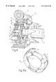
- FIG. 1 is a sectional view of electric machine connected in series with a planetary gear
- FIG. 2 is a schematic top view of the electric machine according to FIG. 1;
- FIG. 3 is a partial front view of an actuating mechanism for switching the planetary gear
- FIG. 4 is a partial perspective view of the planetary gear in a first position I;
- FIG. 5 is a partial perspective view of the planetary gear in a position III
- FIG. 6 is a partial perspective view of the planetary gear in a second position II
- FIG. 7 is a schematic, perspective view of a variant of the electric machine
- FIG. 8 is a sectional view of the electric machine according to FIG. 7;
- FIG. 9 is a perspective, partially sectional view of the electric machine with a planetary gear according to FIG. 8;
- FIG. 10 a is a perspective view of the actuating ring of the planetary gear
- FIG. 10 b is a perspective view of the inner race of the planetary gear
- FIG. 11 is a perspective, partially sectional view of the planetary gear according to FIG. 9 in position I;
- FIG. 12 is a perspective, partially sectional view of the planetary gear according to FIG. 11 in position III;
- FIG. 13 is a perspective, partially sectional view of the planetary gear according to FIG. 11 in position II and
- FIG. 14 is a schematic top view of the electric machine according to FIG. 7 when installed.
- FIG. 1 shows a full sectional depiction and FIG. 2 shows a schematic top view of an electric machine 20 , which is operatively connected to a planetary gear 1 and forms a structural unit with it.
- a rotor 50 of the electric machine 20 is supported in two roller bearings 51 and 52 in a housing 54 .
- the roller bearings 51 and 52 in FIG. 1 are embodied by way of example as deep groove ball bearings. However, it is also possible to use tapered roller bearings, four-point ball bearings, or similar bearing designs.
- the smaller roller bearing 52 shown on the left in the exemplary embodiment depicted is supported with its outer ring in a seat of the housing 54 , which is preferably embodied as cylindrical.
- the design of the electric machine 20 need not be discussed in detail here.
- a motor operation mode is also possible.
- the electric machine 20 should be in a position to start an internal combustion engine of a motor vehicle and, when the internal combustion engine is running, should supply an electrical system of the vehicle as a generator. Therefore, the electric machine 20 must be able to supply a high starting torque when operating as a motor and must be as efficient as possible over wide speed ranges when operating as a generator.
- the rotor 50 of the electric machine 20 is also provided with a gearing, which constitutes a central sun gear 56 of the planetary gear 1 .
- the planetary gear 1 is connected to the electric machine 20 , i.e. a housing 12 of the planetary gear 1 is screwed to and/or interlocked with the housing 54 of the electric machine 20 .
- the rotor 50 with the sun gear 56 and all of the rotating parts of the planetary gear 1 described below, are disposed coaxial to a rotation axis 53 .
- the sun gear 56 meshes with at least three or more planet gears, which will be referred to below as planets 58 .
- the planets 58 are supported so that they can rotate freely,-cannot move axially, and are fastened to a planetary gear carrier 18 .
- This planetary gear carrier 18 is in turn connected to a planetary gear.
- carrier shaft 19 or is embodied of one piece with this shaft, which in turn is operatively connected to a drivetrain of the motor vehicle.
- a preferred position for this operative connection for example, is a transmission input shaft, i.e. in a drivetrain with a manual gear change box and manually actuated coupling,. between these two components.
- the planetary gear carrier 18 is embodied as a short shaft wherein the shaft end disposed on the right in the exemplary embodiment shown is referred to as the planetary gear carrier shaft 19 .
- the planetary gear carrier shaft 19 is supported by a needle bearing 22 in a shoulder 28 that is similar to a hollow shaft.
- the shoulder 28 is embodied as being of one piece with the internal gear 9 of the planetary gear 1 .
- a seal 25 . 1 for example a shaft sealing ring, is inserted between the shoulder 28 and the planetary gear carrier shaft 19 and can be rotated in relation to it.
- the internal gear 9 can either rotate freely or, actuated by switching means, can be fixed either axially in relation to the planetary gear carrier 18 or radially in relation to a housing 12 of the planetary gear 1 . These three possibilities for influencing the internal gear 9 in its relative rotational movement simultaneously define three possible switching positions of the planetary gear 1 .
- these parts In order to axially fix the internal gear 9 in relation to the planetary gear carrier 18 , these parts each have a concentric contact surface disposed parallel to one another, wherein a break lining 29 is alternately provided on one of these two contact surfaces or on both of them.
- the shoulder 28 of the internal. gear 9 is fixed in an inner race 16 so that the internal gear 9 and the inner race 16 can rotate freely in relation to each other, but are axially and radially fixed.
- the inner race 16 is provided with at least one pin 13 which protrudes radially outward and which can slide along exclusively in the axial direction in a lateral opening 21 in the housing 12 . Consequently, the inner race 16 cannot rotate, but can be easily moved in the axial direction, supported in a sliding seat in an end plate 24 which, on its end face, is connected to the housing 12 and at the same time constitutes its cover.
- An actuating ring 5 is also shown, which on its outer circumference, is guided in a sliding seat in the housing 12 and in the end plate 24 so that it can rotate and is axially fixed.
- An inclined plane 6 is provided on the inner circumference of the actuating ring 5 , but its function is explained first in FIG. 3.
- a lever 7 is connected to a brake shoe 8 , which can press radially against the outer circumference of the internal gear 9 depending on the position of the actuating ring 5 .
- the pin 13 is guided through the actuating ring 5 in. a shifting guide path 14 for the pin 13 , which path is not shown in detail here.
- a first seal 25 is provided, which is inserted into a seat in a dividing wall 62 connected to the internal gear 9 , between the sun gear 56 and the right bearing of the rotor 50 , and is placed against a sealing surface of the rotor 50 .
- This seal 25 can, for example, be embodied as a shaft sealing ring.
- the rotor shaft is installed first, then the seal 25 is inserted, and only then is the sun gear 56 affixed to the rotor shaft.
- the second seal 25 is .
- FIG. 2 shows a gearing of a ring gear 4 which is attached to the actuating ring 5 and is operatively connected to a pinion 3 of an electric motor 2 disposed axially parallel to the electric machine 20 .
- the actuating ring 5 can be rotated by a fixed angle, by means of which a transmission change of the planetary gear 1 can be produced.
- the pin 13 is fixed in the inner race 16 . Because of the guidance of the lateral opening 21 , which guidance only extends for a short distance in the axial direction, the pin 13 and therefore the inner race 16 cannot rotate in the circumference direction. A rotation in the circumference direction is only possible for the actuating ring 5 , as long as the gearing of the ring gear 4 permits this. Since the shifting guide path 14 , which extends along a path in the circumference direction for a distance that corresponds approximately to the length of the gearing of the ring gear 4 , is inclined toward the electric machine 20 at one end, the end pointing downward in the depiction shown, the pin 13 and the inner race 16 connected to it are slid in the axial direction when the actuating ring 5 rotates.
- the inner race 16 On its outer circumference, the inner race 16 is guided in the end plate 24 connected to the end face of the housing 12 in such a way that this inner race can move axially without play and without tilting.
- the inner race 16 On its inner circumference, the inner race 16 is connected to the internal gear 9 by means of the roller bearing 17 , which absorbs axial and radial forces, and for this purpose, the internal gear has a shoulder 28 , which is similar to a hollow shaft and has a smaller diameter than the internal gear 9 itself.
- a bearing suitable for the roller bearing 17 is, for example, a ball bearing, a tapered roller bearing, or a four-point ball bearing, which can transmit sufficient axial and radial forces. This operating position of the planetary gear 1 will be referred to below as position I.
- FIG. 3 shows another function of the actuating ring 5 in a partial section III—III from FIG. 1 . Parts which are the same as those in the preceding Figs. are provided with the same reference numerals and are not explained further.
- This top view shows the gearing 4 that is let into the -. circumference of the actuating ring 5 and makes it possible to rotate the actuating ring by a particular angle in its sliding seat in the housing 12 . In the exemplary embodiment shown, this takes place by means of the electric motor 2 , which acts as a servomotor and whose driven pinion 3 is operatively connected to the gearing 4 .
- the actuating ring 5 On its inner circumference, the actuating ring 5 is provided with at least two inclined planes 6 , each a section with a continually decreasing radius, which in a rotation of the actuating ring 5 , presses toward the right against a head 7 . 1 of a lever 7 and pivots it inward, i.e. in the direction of the rotation axis 53 , in a rotation point 7 . 2 fixed to the housing.
- the radius of the inclined plane 6 can taper more sharply at the beginning and less sharply at the end. In this manner, the beginning of the actuation path produces a greater stroke of the lever 7 .
- An arc-shaped brake shoe 8 is rotatably fastened to the head 7 . 1 of the lever 7 and is provided with a brake lining 15 on its inside. This inside follows the contour of the outer circumference of the internal gear 9 and can consequently brake it or completely lock it.
- a spring 26 presses the lever 7 toward the inclined plane 6 , i.e. away from the internal gear 9 .
- the arc length of the inclined plane 6 suitably corresponds to the adjustment of the actuating ring 5 , which is predetermined by the arc length of the gearing of the ring gear 4 .
- at least two symmetrically opposed inclined planes 6 having associated levers 7 with brake shoes 8 and a brake lining 15 are provided on the actuating ring 5 .
- FIGS. 4, 5 , and 6 show an exemplary number of four planets 58 .
- At least three planets 58 are required in order to assure a definite fixing of the planets 58 , the internal gear 9 , and the sun gear 56 .
- more than three or four planets distributed as evenly is possible over the circumference can also be used, but increasing friction losses must be taken into account as a result of more gears being engaged with one another.
- FIG. 4 shows the planetary gear in a first switching position I.
- the actuating ring 5 is rotated toward the left, as a result of which the two inclined planes 6 , which are disposed on the inner diameter of the actuating ring 5 and taper in the circumference direction, are rotated, and respectively press against the head 7 . 1 of the lever 7 and thereby press the brake shoes 8 with the brake linings 15 externally onto the internal gear 9 of the planetary gear 1 .
- the internal gear 9 is thus locked and the speed of the rotor 50 is reduced to the speed of the planetary gear carrier shaft 19 .
- FIG. 5 shows the switching position III of the planetary gear 1 .
- the switching position I is canceled; at this point, the pins 13 are not moved in the radial direction. Since the pins are disposed at a point along their path of travel in which the pin travel path, which is disposed in the actuating ring 5 and is predetermined by the guide plane 14 , only permits travel in the circumference direction, they spin in place. Since the two brake linings 15 are now released, the “neutral” position has been reached. Driven by the planets 58 , the internal gear 9 can rotate freely since it is not fixed in relation to either the housing 12 or the planetary gear carrier 18 . Consequently, no driving moment is acting on the rotor 50 —it can coast freely.
- FIG. 6 shows the planetary gear 1 in the other switching position II.
- the actuating ring 5 is rotated completely toward the right as a result of which the pins 13 reach the point in their path of travel where the axial movement of the inner race 16 also begins.
- the movement of the pins 13 in the arc-shaped shifting guide path 14 in the actuating ring 5 continues, wherein a self-locking is also possible.
- the internal gear is now moved by way of the roller bearing 17 in the direction of the planetary gear carrier 18 by means of the inner race that is guided with the pins 13 in the actuating ring 5 .
- the inner race 16 is held with the planetary gear carrier shaft 19 by means of the brake lining 29 on the inner end face of the hollow chamber 9 .
- the inner race 16 can execute only axial movements.
- the speed of the rotor 50 corresponds to the speed of the planetary gear carrier 50 .
- FIGS. 7 and 8 show a variant of the electric machine 2 with an operatively connected planetary gear 1 .
- Parts which are the same as those in the preceding FIGS. are provided with the same reference numerals and are not explained further.
- this electric machine 2 which functions as a servomotor for switching the planetary gear 1 , is disposed with its rotation axis perpendicular to the rotation axis 53 of the planetary gear 1 and acts on a modified actuating ring 5 . 1 by means of a worm drive 3 . 1 instead of a pinion 3 .
- FIG. 8 shows a full sectional view of the electric machine 20 with an operatively connected planetary gear 1 according to FIG. 7 . Since in this variant, essentially only the actuation of the actuating ring 5 . 1 and the axial introduction of force onto the internal gear 9 by means of a modified inner race 16 . 1 has been modified in comparison to the embodiment shown in FIG. 1 but the rest of the design remains virtually unchanged, only the modified parts and their function are discussed in detail below.
- the adjustment of the planetary gear 1 takes place through an actuation of the electric motor 2 , which can rotate the actuating ring 5 . 1 by way of its worm drive 3 . 1 which engages with the gearing 4 .
- the radial locking of the internal gear 9 by means of the at least two brake shoes 8 that are connected to the actuating ring 5 . 1 functions in the same manner described above.
- the axial fixing of the planetary gear carrier 18 in relation to the internal gear 9 is modified in this variant since a pin guided in a shifting guide path is not provided here, but rather effective surfaces in the actuating ring 5 . 1 and the inner race 16 . 1 , which surfaces correspond axially with one another.
- These effective surfaces are comprised of at least two axially disposed projections 30 in the actuating ring 5 . 1 , which cooperate with at least two correspondingly fitting, axially disposed inclined planes 31 in the inner race 16 . 1 in such a way that when the actuating ring 5 . 1 rotates, the inner race 16 . 1 can undergo an axial movement of the internal gear 9 in relation to the planetary gear carrier 18 .
- a direct axial contact of the inner race 16 . 1 against a corresponding surface of the internal gear 9 is provided so that in this embodiment, the roller bearing 17 only has to provide for the radial fixing and support of the inner race 16 . 1 in relation to the shoulder 28 of the internal gear 9 .
- the shoulder 28 is supported on the planetary gear carrier shaft 19 by means of needle bearings 22 .
- FIG. 9 is a perspective, partially sectional view of the electric machine 20 with a planetary gear 1 according to FIG. 8 .
- one of at least two pins 41 can also be seen, which provide for an axially restricted guidance of the actuating ring 5 . 1 and thereby ensure that the internal gear 9 floats freely in the positions I and III and prevent it from sliding uncontrollably against the planetary gear carrier 18 .
- the internal gear 9 When switching from the position II, the internal gear 9 initially remains stationary and does not follow the axial stroke of the inner race 16 . 1 , as a result of which it can easily slide against the planetary gear carrier 18 .
- At least two inclined planes 40 which correspond with the pins 41 , are provided on the outer diameter of the actuating ring 5 . 1 in the axial direction and the pins 41 slide along these inclined planes and consequently pull the internal gear 9 away from the planetary gear carrier 18 .
- FIG. 10 a is a perspective view of the actuating ring 5 . 1 .
- Both of the radial inclined planes 6 and the at least two projections 30 that act in the axial direction on its circular, flat inside can be seen clearly here.
- the projections 30 must be disposed as precisely opposite one another as possible, i.e. must be offset by an angle of 180°.
- there to be three, four, or more projections 30 which should be distributed in a correspondingly uniform fashion over the circumference of the circle.
- FIG. 10 b shows the modified inner race 16 . 1 with the inclined planes 31 , which respectively correspond to the projections 30 in the actuating ring 5 . 1 , as well as an adjusting spring 33 radially affixed to the outside or a pin.
- This pin or this adjusting spring 33 slide in a fitted guide in the housing 12 or in the end plate 24 and prevents the rotation of the inner race 16 . 1 , which consequently can only be moved axially.
- FIG. 11 shows a partially sectional view of the switching position I.
- the axially free-floating nature of the reciprocally mobile, axial coupling which is comprised of the planetary gear carrier 18 and the internal gear 9 with the brake lining 29 affixed to it are clearly visible here.
- This view also shows an inclined plane 31 attached to the round, flat side of the inner race 16 . 1 and which can be pressed against a corresponding projection 30 in the actuating ring 5 . 1 as soon as the actuating ring is rotated into a corresponding position.
- FIG. 12 is a perspective, partially sectional view of the neutral switching position III of the planetary gear 1 .
- FIG. 13 shows the switching position II of the planetary gear 1 .
- the closed axial coupling is shown here.
- FIG. 14 is a schematic top view of the electric machine 20 according to FIG. 7 when installed.
- the output i.e. the planetary gear carrier shaft 19 of the planetary gear 1
- the drivetrain of the motor vehicle i.e. the planetary gear carrier shaft 19 of the planetary gear 1
- a manually shifted transmission 27 of the motor vehicle can be seen, whose input shaft is operatively connected to the planet gear carrier shaft 19 in a perpendicular fashion. For example, this can take place by means of a pair of mated bevel gears or an end gearing with a ring gear.
Landscapes
- Engineering & Computer Science (AREA)
- General Engineering & Computer Science (AREA)
- Mechanical Engineering (AREA)
- Power Engineering (AREA)
- Chemical & Material Sciences (AREA)
- Combustion & Propulsion (AREA)
- Connection Of Motors, Electrical Generators, Mechanical Devices, And The Like (AREA)
- Retarders (AREA)
- General Details Of Gearings (AREA)
Applications Claiming Priority (5)
| Application Number | Priority Date | Filing Date | Title |
|---|---|---|---|
| DE19744156 | 1997-10-07 | ||
| DE19744156 | 1997-10-07 | ||
| DE19810592 | 1998-03-12 | ||
| DE19810592A DE19810592A1 (de) | 1997-10-07 | 1998-03-12 | Elektrische Maschine |
| PCT/DE1998/002961 WO1999018648A1 (de) | 1997-10-07 | 1998-10-07 | Elektrische maschine |
Publications (1)
| Publication Number | Publication Date |
|---|---|
| US6428442B1 true US6428442B1 (en) | 2002-08-06 |
Family
ID=26040637
Family Applications (1)
| Application Number | Title | Priority Date | Filing Date |
|---|---|---|---|
| US09/529,212 Expired - Fee Related US6428442B1 (en) | 1997-10-07 | 1998-10-07 | Electric motor |
Country Status (6)
| Country | Link |
|---|---|
| US (1) | US6428442B1 (pt) |
| EP (1) | EP1020008B1 (pt) |
| JP (1) | JP2001519504A (pt) |
| AU (1) | AU732791B2 (pt) |
| BR (1) | BR9812726A (pt) |
| WO (1) | WO1999018648A1 (pt) |
Cited By (26)
| Publication number | Priority date | Publication date | Assignee | Title |
|---|---|---|---|---|
| US20030085628A1 (en) * | 2001-11-06 | 2003-05-08 | Hitachi, Ltd. And Sumitomo Heavy Industries, Ltd. | Electric rotating machine |
| US6605019B1 (en) * | 1999-04-19 | 2003-08-12 | Zf Friedrichshafen Ag | Switching device of a two-stage planetary gear |
| US6676554B2 (en) * | 2000-09-15 | 2004-01-13 | Campagnolo S.R.L. | Electrically powered actuator for a bicycle component |
| US6746354B1 (en) * | 1999-05-21 | 2004-06-08 | Zf Friedrichshafen Ag | Drive system for a motor vehicle |
| US20050113207A1 (en) * | 2003-11-25 | 2005-05-26 | Wang Yong Q. | Actuator for shift-by-wire automatic transmission system |
| US20050250610A1 (en) * | 2004-05-06 | 2005-11-10 | Bernd Fruehwald | Gear motor with fail-safe device |
| US20060005544A1 (en) * | 2004-07-12 | 2006-01-12 | Honeywell International Inc. | Synchronizing stationary clutch for compression braking with a two spool gas turbine engine |
| US20060052204A1 (en) * | 2002-09-05 | 2006-03-09 | Harald Eckert | Electromagnetic selection device for a two-stage planetary gear set |
| US20060117876A1 (en) * | 2004-12-07 | 2006-06-08 | Remy International, Inc. | Sealed and oil lubricated starter motor gear reduction and overrunning clutch mechanism |
| US20070029887A1 (en) * | 2003-03-31 | 2007-02-08 | Yamaha Hatsudoki Kabushiki Kaisha | Rotating electric machine and electric vehicle |
| US7239032B1 (en) | 2005-11-18 | 2007-07-03 | Polaris Industries Inc. | Starter-generator |
| US20080054827A1 (en) * | 2006-08-29 | 2008-03-06 | Derek States | Power system rating converter |
| US20080152517A1 (en) * | 2006-12-26 | 2008-06-26 | Kanzaki Kokyukoki Mfg. Co., Ltd. | Multiple pump unit and vehicle with multiple pump unit |
| US20080150312A1 (en) * | 2006-12-20 | 2008-06-26 | Globe Motors, Inc. | Seat storage actuator |
| US20090098972A1 (en) * | 2006-03-21 | 2009-04-16 | Zf Friedrichshafen Ag | Two-stage machine tool gearing, in particular spindle gearing |
| EP1555456A3 (de) * | 2004-01-16 | 2009-12-09 | LuK Lamellen und Kupplungsbau Beteiligungs KG | Steuerung eines Planetengetriebes mit einem Startergenerator im Nebenabtrieb durch Drehzahlsteuerung des Startergenerators |
| WO2011060362A1 (en) * | 2009-11-16 | 2011-05-19 | Remy Technologies, Llc | Electric motor with planetary gear set |
| US20110290071A1 (en) * | 2009-02-17 | 2011-12-01 | Zf Friedrichshafen Ag | Hybrid drive for a motor vehicle |
| CN102386716A (zh) * | 2011-12-01 | 2012-03-21 | 卧龙电气集团股份有限公司 | 启动电机 |
| US20120271493A1 (en) * | 2011-04-21 | 2012-10-25 | Deere & Company | In-Vehicle Estimation of Electric Traction Motor Performance |
| CN103715794A (zh) * | 2013-12-05 | 2014-04-09 | 西安交通大学 | 一种汽车用起动发电一体化的开关磁通电机 |
| FR3011052A1 (fr) * | 2013-09-23 | 2015-03-27 | Mijno Prec Gearing | Reducteur planetaire a double vitesse |
| DE102014217129A1 (de) * | 2014-08-28 | 2016-03-03 | Robert Bosch Gmbh | Startvorrichtung für eine Brennkraftmaschine |
| US9481256B2 (en) | 2014-01-30 | 2016-11-01 | Amp Electric Vehicles Inc. | Onboard generator drive system for electric vehicles |
| US20190376484A1 (en) * | 2018-06-06 | 2019-12-12 | GM Global Technology Operations LLC | Vehicle Engine Electric Starter Motor with Multiple Speed Ratios |
| CN117620324A (zh) * | 2023-12-21 | 2024-03-01 | 杭州新世宝电动转向系统有限公司 | 转向器蜗轮蜗杆磨合装置 |
Families Citing this family (2)
| Publication number | Priority date | Publication date | Assignee | Title |
|---|---|---|---|---|
| DE10032681B4 (de) * | 2000-07-05 | 2015-12-10 | Daimler Ag | Startergenerator |
| WO2013186032A1 (de) * | 2012-06-13 | 2013-12-19 | Schaeffler Technologies AG & Co. KG | Verfahren zur steuerung eines antriebsstrangs mit riemenscheibengenerator |
Citations (11)
| Publication number | Priority date | Publication date | Assignee | Title |
|---|---|---|---|---|
| US2327769A (en) | 1941-04-02 | 1943-08-24 | Gen Motors Corp | Generator overdrive |
| US2600762A (en) | 1951-08-04 | 1952-06-17 | Jack & Heintz Prec Ind Inc | Starter generator |
| JPS58140468A (ja) * | 1982-02-17 | 1983-08-20 | Hitachi Ltd | リダクシヨンスタ−タ |
| US4791833A (en) * | 1984-07-16 | 1988-12-20 | Japan Storage Battery Co., Ltd. | Reduction gear mechanism for motor-driven drill incorporating speed changing mechanism |
| US4800766A (en) * | 1987-02-25 | 1989-01-31 | Mitsubishi Denki Kabushiki Kaisha | Coaxial type starter |
| US4870875A (en) * | 1987-04-03 | 1989-10-03 | Mitsubishi Denki Kabushiki Kaisha | Driving device for auxiliary device |
| US4892013A (en) * | 1987-07-30 | 1990-01-09 | Olympic Co. Ltd. | Variable speed gearing in rotary electric tool |
| US4898249A (en) * | 1987-08-05 | 1990-02-06 | Olympic Co., Ltd. | Rotary electric tool |
| DE8914904U1 (pt) | 1989-12-19 | 1990-02-15 | General Electric Co., Schenectady, N.Y., Us | |
| US5418400A (en) | 1993-12-27 | 1995-05-23 | Ford Motor Company | Integrated generator and starter motor |
| US5685796A (en) * | 1996-02-20 | 1997-11-11 | Industrial Technology Research Institute | Planetary gearing unit |
-
1998
- 1998-10-07 AU AU12241/99A patent/AU732791B2/en not_active Ceased
- 1998-10-07 JP JP2000515320A patent/JP2001519504A/ja active Pending
- 1998-10-07 US US09/529,212 patent/US6428442B1/en not_active Expired - Fee Related
- 1998-10-07 EP EP98955374A patent/EP1020008B1/de not_active Expired - Lifetime
- 1998-10-07 BR BR9812726-8A patent/BR9812726A/pt not_active IP Right Cessation
- 1998-10-07 WO PCT/DE1998/002961 patent/WO1999018648A1/de not_active Application Discontinuation
Patent Citations (11)
| Publication number | Priority date | Publication date | Assignee | Title |
|---|---|---|---|---|
| US2327769A (en) | 1941-04-02 | 1943-08-24 | Gen Motors Corp | Generator overdrive |
| US2600762A (en) | 1951-08-04 | 1952-06-17 | Jack & Heintz Prec Ind Inc | Starter generator |
| JPS58140468A (ja) * | 1982-02-17 | 1983-08-20 | Hitachi Ltd | リダクシヨンスタ−タ |
| US4791833A (en) * | 1984-07-16 | 1988-12-20 | Japan Storage Battery Co., Ltd. | Reduction gear mechanism for motor-driven drill incorporating speed changing mechanism |
| US4800766A (en) * | 1987-02-25 | 1989-01-31 | Mitsubishi Denki Kabushiki Kaisha | Coaxial type starter |
| US4870875A (en) * | 1987-04-03 | 1989-10-03 | Mitsubishi Denki Kabushiki Kaisha | Driving device for auxiliary device |
| US4892013A (en) * | 1987-07-30 | 1990-01-09 | Olympic Co. Ltd. | Variable speed gearing in rotary electric tool |
| US4898249A (en) * | 1987-08-05 | 1990-02-06 | Olympic Co., Ltd. | Rotary electric tool |
| DE8914904U1 (pt) | 1989-12-19 | 1990-02-15 | General Electric Co., Schenectady, N.Y., Us | |
| US5418400A (en) | 1993-12-27 | 1995-05-23 | Ford Motor Company | Integrated generator and starter motor |
| US5685796A (en) * | 1996-02-20 | 1997-11-11 | Industrial Technology Research Institute | Planetary gearing unit |
Non-Patent Citations (1)
| Title |
|---|
| "Neues Starter-Generator-System", MTZ Motortechnishce Zeitschrift, vol. 58, No. 10, Oct. 1997, p. 630. |
Cited By (51)
| Publication number | Priority date | Publication date | Assignee | Title |
|---|---|---|---|---|
| US6605019B1 (en) * | 1999-04-19 | 2003-08-12 | Zf Friedrichshafen Ag | Switching device of a two-stage planetary gear |
| US6746354B1 (en) * | 1999-05-21 | 2004-06-08 | Zf Friedrichshafen Ag | Drive system for a motor vehicle |
| US6676554B2 (en) * | 2000-09-15 | 2004-01-13 | Campagnolo S.R.L. | Electrically powered actuator for a bicycle component |
| US7105964B2 (en) * | 2001-11-06 | 2006-09-12 | Hitachi, Ltd. | Electric rotating machine |
| US20030085628A1 (en) * | 2001-11-06 | 2003-05-08 | Hitachi, Ltd. And Sumitomo Heavy Industries, Ltd. | Electric rotating machine |
| US7300376B2 (en) * | 2002-09-05 | 2007-11-27 | Zf Friedrichshafen Ag | Electromagnetic selection device for a two-stage planetary gear set |
| US20060052204A1 (en) * | 2002-09-05 | 2006-03-09 | Harald Eckert | Electromagnetic selection device for a two-stage planetary gear set |
| US7309941B2 (en) | 2003-03-31 | 2007-12-18 | Yamaha Hatsudoki Kabushiki Kaisha | Rotating electric machine and electric vehicle |
| US20070029887A1 (en) * | 2003-03-31 | 2007-02-08 | Yamaha Hatsudoki Kabushiki Kaisha | Rotating electric machine and electric vehicle |
| US20070235281A1 (en) * | 2003-11-25 | 2007-10-11 | Wang Yong Q | Actuator for shift-by-wire automatic transmission system |
| US7241244B2 (en) * | 2003-11-25 | 2007-07-10 | Dura Global Technologies, Inc. | Actuator for shift-by-wire automatic transmission system |
| US7354372B2 (en) * | 2003-11-25 | 2008-04-08 | Dura Global Technologies, Inc. | Actuator for shift-by-wire automatic transmission system |
| US20050113207A1 (en) * | 2003-11-25 | 2005-05-26 | Wang Yong Q. | Actuator for shift-by-wire automatic transmission system |
| EP1555456A3 (de) * | 2004-01-16 | 2009-12-09 | LuK Lamellen und Kupplungsbau Beteiligungs KG | Steuerung eines Planetengetriebes mit einem Startergenerator im Nebenabtrieb durch Drehzahlsteuerung des Startergenerators |
| US7223196B2 (en) * | 2004-05-06 | 2007-05-29 | Buehler Motor Gmbh | Gear motor with fail-safe device |
| US20050250610A1 (en) * | 2004-05-06 | 2005-11-10 | Bernd Fruehwald | Gear motor with fail-safe device |
| US7185496B2 (en) | 2004-07-12 | 2007-03-06 | Honeywell International, Inc. | Synchronizing stationary clutch of compression braking with a two spool gas turbine engine |
| US20060005544A1 (en) * | 2004-07-12 | 2006-01-12 | Honeywell International Inc. | Synchronizing stationary clutch for compression braking with a two spool gas turbine engine |
| US20060117876A1 (en) * | 2004-12-07 | 2006-06-08 | Remy International, Inc. | Sealed and oil lubricated starter motor gear reduction and overrunning clutch mechanism |
| US7239032B1 (en) | 2005-11-18 | 2007-07-03 | Polaris Industries Inc. | Starter-generator |
| US7400053B2 (en) | 2005-11-18 | 2008-07-15 | Polaris Industries Inc. | Starter-generator |
| US20080001407A1 (en) * | 2005-11-18 | 2008-01-03 | Polaris Industries Inc. | Starter-generator |
| US20090098972A1 (en) * | 2006-03-21 | 2009-04-16 | Zf Friedrichshafen Ag | Two-stage machine tool gearing, in particular spindle gearing |
| US8047955B2 (en) * | 2006-03-21 | 2011-11-01 | Zf Friedrichshafen Ag | Two-stage machine tool gearing, in particular spindle gearing |
| US20080054827A1 (en) * | 2006-08-29 | 2008-03-06 | Derek States | Power system rating converter |
| US7600801B2 (en) | 2006-12-20 | 2009-10-13 | Globe Motors, Inc. | Seat storage actuator |
| US20080150312A1 (en) * | 2006-12-20 | 2008-06-26 | Globe Motors, Inc. | Seat storage actuator |
| US20080152517A1 (en) * | 2006-12-26 | 2008-06-26 | Kanzaki Kokyukoki Mfg. Co., Ltd. | Multiple pump unit and vehicle with multiple pump unit |
| US20110290071A1 (en) * | 2009-02-17 | 2011-12-01 | Zf Friedrichshafen Ag | Hybrid drive for a motor vehicle |
| CN102317655B (zh) * | 2009-02-17 | 2015-11-25 | Zf腓德烈斯哈芬股份公司 | 用于机动车的混合动力驱动装置 |
| US8523726B2 (en) * | 2009-02-17 | 2013-09-03 | Zf Friedrichshafen Ag | Hybrid drive for a motor vehicle |
| CN102317655A (zh) * | 2009-02-17 | 2012-01-11 | Zf腓德烈斯哈芬股份公司 | 用于机动车的混合动力驱动装置 |
| US20110115320A1 (en) * | 2009-11-16 | 2011-05-19 | Remy Technologies, Llc | Reversible planetary gear assembly |
| WO2011060362A1 (en) * | 2009-11-16 | 2011-05-19 | Remy Technologies, Llc | Electric motor with planetary gear set |
| US20110114399A1 (en) * | 2009-11-16 | 2011-05-19 | Remy Technologies, Llc | Traction motor and planetary gear assembly |
| US8771123B2 (en) | 2009-11-16 | 2014-07-08 | Remy Technologies Llc | Reversible planetary gear assembly |
| US8449429B2 (en) | 2009-11-16 | 2013-05-28 | Remy Technologies Llc | Reversible planetary gear assembly |
| US20110115321A1 (en) * | 2009-11-16 | 2011-05-19 | Remy Technologies, Llc | Electric motor and planetary gear assembly |
| US8633622B2 (en) | 2009-11-16 | 2014-01-21 | Remy Technologies Llc | Electric motor and planetary gear assembly |
| US8672070B2 (en) | 2009-11-16 | 2014-03-18 | Remy Technologies, Llc | Traction motor and planetary gear assembly |
| US8666574B2 (en) * | 2011-04-21 | 2014-03-04 | Deere & Company | In-vehicle estimation of electric traction motor performance |
| US20120271493A1 (en) * | 2011-04-21 | 2012-10-25 | Deere & Company | In-Vehicle Estimation of Electric Traction Motor Performance |
| CN102386716B (zh) * | 2011-12-01 | 2014-03-19 | 卧龙电气集团股份有限公司 | 启动电机 |
| CN102386716A (zh) * | 2011-12-01 | 2012-03-21 | 卧龙电气集团股份有限公司 | 启动电机 |
| FR3011052A1 (fr) * | 2013-09-23 | 2015-03-27 | Mijno Prec Gearing | Reducteur planetaire a double vitesse |
| CN103715794A (zh) * | 2013-12-05 | 2014-04-09 | 西安交通大学 | 一种汽车用起动发电一体化的开关磁通电机 |
| CN103715794B (zh) * | 2013-12-05 | 2016-05-04 | 西安交通大学 | 一种汽车用起动发电一体化的开关磁通电机 |
| US9481256B2 (en) | 2014-01-30 | 2016-11-01 | Amp Electric Vehicles Inc. | Onboard generator drive system for electric vehicles |
| DE102014217129A1 (de) * | 2014-08-28 | 2016-03-03 | Robert Bosch Gmbh | Startvorrichtung für eine Brennkraftmaschine |
| US20190376484A1 (en) * | 2018-06-06 | 2019-12-12 | GM Global Technology Operations LLC | Vehicle Engine Electric Starter Motor with Multiple Speed Ratios |
| CN117620324A (zh) * | 2023-12-21 | 2024-03-01 | 杭州新世宝电动转向系统有限公司 | 转向器蜗轮蜗杆磨合装置 |
Also Published As
| Publication number | Publication date |
|---|---|
| AU1224199A (en) | 1999-04-27 |
| AU732791B2 (en) | 2001-05-03 |
| JP2001519504A (ja) | 2001-10-23 |
| BR9812726A (pt) | 2000-08-22 |
| EP1020008A1 (de) | 2000-07-19 |
| WO1999018648A1 (de) | 1999-04-15 |
| EP1020008B1 (de) | 2003-07-23 |
Similar Documents
| Publication | Publication Date | Title |
|---|---|---|
| US6428442B1 (en) | Electric motor | |
| CA2397181C (en) | Reduction gear for a starter-generator of an internal combustion engine | |
| KR100332136B1 (ko) | 시동 전동기 | |
| EP2305501B1 (en) | Two-speed transmission for electric vehicles | |
| EP2006533B1 (en) | Starter for engines | |
| US4674612A (en) | Auxiliary equipment transmission | |
| US7018314B2 (en) | Engine starter with impact absorber | |
| US5372106A (en) | Drive assembly for auxiliary units | |
| CN105960538B (zh) | 具有超越能力和带起动能力的解耦器 | |
| KR20080040594A (ko) | 컴팩트한 구성을 갖는 스타터 | |
| JP2004270616A (ja) | スタータ | |
| KR20050033828A (ko) | 과대토크흡수장치를 구비한 스타터 | |
| US4974463A (en) | Starting motor with a translatable idler/pinion gear | |
| US6425839B1 (en) | Auxiliary generator set with variable transmission for an internal combustion engine | |
| JP2003120765A (ja) | 可変速モータ・ジェネレータ | |
| EP0482628B1 (en) | Intermediate gear type starter | |
| JP4229765B2 (ja) | 風車ブレードのピッチ角制御装置 | |
| FR2684733A1 (fr) | Dispositif pour actionner par moteur electrique une liaison par friction entre deux organes de transmission d'une transmission a engranages d'un vehicule automobile. | |
| US5743139A (en) | Starter with alignment means for planetary gears | |
| US7824271B2 (en) | Device for adjusting the relative angular position of two rotating elements | |
| US20050045445A1 (en) | Clutch by wire having multiple starter-generator means | |
| US6789438B2 (en) | Engine starting apparatus | |
| RU2048653C1 (ru) | Пусковое устройство | |
| JP4310276B2 (ja) | 無段階変速機 | |
| KR20010015699A (ko) | 전기 기계 |
Legal Events
| Date | Code | Title | Description |
|---|---|---|---|
| AS | Assignment |
Owner name: ROBERT BOSCH GMBH, GERMANY Free format text: ASSIGNMENT OF ASSIGNORS INTEREST;ASSIGNORS:TURGAY, BARLAS;BOLZ, MARTIN-PETER;GLAUNING, JUERGEN;REEL/FRAME:010941/0957;SIGNING DATES FROM 20000312 TO 20000502 |
|
| FEPP | Fee payment procedure |
Free format text: PAYOR NUMBER ASSIGNED (ORIGINAL EVENT CODE: ASPN); ENTITY STATUS OF PATENT OWNER: LARGE ENTITY |
|
| FPAY | Fee payment |
Year of fee payment: 4 |
|
| REMI | Maintenance fee reminder mailed | ||
| LAPS | Lapse for failure to pay maintenance fees | ||
| STCH | Information on status: patent discontinuation |
Free format text: PATENT EXPIRED DUE TO NONPAYMENT OF MAINTENANCE FEES UNDER 37 CFR 1.362 |
|
| FP | Lapsed due to failure to pay maintenance fee |
Effective date: 20100806 |