US6355092B1 - Apparatus and method for performing membrane gas/liquid absorption at elevated pressure - Google Patents
Apparatus and method for performing membrane gas/liquid absorption at elevated pressure Download PDFInfo
- Publication number
- US6355092B1 US6355092B1 US09/423,435 US42343599A US6355092B1 US 6355092 B1 US6355092 B1 US 6355092B1 US 42343599 A US42343599 A US 42343599A US 6355092 B1 US6355092 B1 US 6355092B1
- Authority
- US
- United States
- Prior art keywords
- pressure
- membrane
- gas
- liquid phase
- phase
- Prior art date
- Legal status (The legal status is an assumption and is not a legal conclusion. Google has not performed a legal analysis and makes no representation as to the accuracy of the status listed.)
- Expired - Lifetime
Links
Images

Classifications
-
- B—PERFORMING OPERATIONS; TRANSPORTING
- B01—PHYSICAL OR CHEMICAL PROCESSES OR APPARATUS IN GENERAL
- B01D—SEPARATION
- B01D53/00—Separation of gases or vapours; Recovering vapours of volatile solvents from gases; Chemical or biological purification of waste gases, e.g. engine exhaust gases, smoke, fumes, flue gases, aerosols
- B01D53/22—Separation of gases or vapours; Recovering vapours of volatile solvents from gases; Chemical or biological purification of waste gases, e.g. engine exhaust gases, smoke, fumes, flue gases, aerosols by diffusion
- B01D53/229—Integrated processes (Diffusion and at least one other process, e.g. adsorption, absorption)
-
- B—PERFORMING OPERATIONS; TRANSPORTING
- B01—PHYSICAL OR CHEMICAL PROCESSES OR APPARATUS IN GENERAL
- B01D—SEPARATION
- B01D53/00—Separation of gases or vapours; Recovering vapours of volatile solvents from gases; Chemical or biological purification of waste gases, e.g. engine exhaust gases, smoke, fumes, flue gases, aerosols
- B01D53/22—Separation of gases or vapours; Recovering vapours of volatile solvents from gases; Chemical or biological purification of waste gases, e.g. engine exhaust gases, smoke, fumes, flue gases, aerosols by diffusion
-
- B—PERFORMING OPERATIONS; TRANSPORTING
- B01—PHYSICAL OR CHEMICAL PROCESSES OR APPARATUS IN GENERAL
- B01D—SEPARATION
- B01D63/00—Apparatus in general for separation processes using semi-permeable membranes
- B01D63/02—Hollow fibre modules
-
- B—PERFORMING OPERATIONS; TRANSPORTING
- B01—PHYSICAL OR CHEMICAL PROCESSES OR APPARATUS IN GENERAL
- B01D—SEPARATION
- B01D2313/00—Details relating to membrane modules or apparatus
- B01D2313/18—Specific valves
-
- B—PERFORMING OPERATIONS; TRANSPORTING
- B01—PHYSICAL OR CHEMICAL PROCESSES OR APPARATUS IN GENERAL
- B01D—SEPARATION
- B01D2319/00—Membrane assemblies within one housing
- B01D2319/04—Elements in parallel
Definitions
- the present application relates to an apparatus and method for performing membrane gas/liquid absorption at elevated pressure.
- Membrane gas/liquid absorption is a very flexible and versatile technique, which can be used for specific absorption of diverse compounds from a gas phase, depending on, inter alia, the membrane used, the liquid phase used, and the gas stream to be cleaned.
- membrane gas/liquid absorption can be used for specifically absorbing carbon dioxide and H 2 S (European application 0,751,815), oxidizable and reducible constituents such as mercury vapour (PCT application NL 96/00279), and also for removing water vapour (European application 0,524,242 by Applicant).
- the invention therefore relates to an apparatus for performing membrane gas/liquid absorption at elevated pressure, comprising:
- a pressure vessel ( 1 ) which encloses an essentially closed chamber ( 2 );
- pressure vessel ( 1 ), inlet ( 3 a ) and outlet ( 4 a ) and membrane unit ( 5 ) are provided in such a way in chamber ( 2 ) that the gas phase can be directed past membrane element ( 6 ) in a flow direction essentially perpendicular to the flow direction of the liquid phase through membrane element ( 6 ), exchange of components to be absorbed being able to take place between the gas phase and the liquid phase through (the wall of) membrane element ( 6 ).
- the invention further relates to a method for performing membrane gas/liquid absorption at elevated pressure for absorbing one or more components from a gas phase, employing the above-described apparatus, comprising
- the gas phase comprising the one or more components to be absorbed, via inlet ( 3 a ) and outlet ( 4 a ) through chamber ( 2 ) past the one or more membrane elements ( 6 ), the gas phase having a pressure of more than 4 bar, preferably more than 10 bar, more preferably 50-200 bar;
- the membrane gas/liquid absorption is performed with so-called “cross-flow”, i.e. the direction of the gas phase containing the one or more components to be absorbed is perpendicular to the plane of flow of the liquid phase.
- Pressure vessel ( 1 ) is preferably essentially cylindrical or encloses an essentially cylindrical chamber ( 2 ). Whilst, in the operating position shown, the longitudinal axis of pressure vessel ( 1 ) is arranged essentially vertically, other setups are also possible, since membrane absorption is essentially independent of the orientation of the pressure vessel. These additional degrees of freedom regarding the set-up of the membrane absorber are an important advantage of membrane gas absorption compared with (for example) the use of packed columns which operate under the influence of gravity and therefore always have to be operated essentially vertically to achieve the desired counterflow.
- Pressure vessel ( 1 ) may comprise guide means for controlling the flow of the gas phase through chamber ( 2 ).
- Membrane element ( 6 ) has such a shape that it defines at least a feed-through channel ( 7 ).
- membrane element ( 6 ) may consist of one membrane or of an assembly of a plurality of membranes, which form/enclose the feed-through channel; for example, membrane unit ( 5 ) may consist of planar membranes having transport channels, membranes that form a so-called “plate-and-frame” module or are in the form of spirally coiled membranes.
- Membrane element ( 6 ) is preferably in the form of a hollow fibre.
- the membranes can be made of any suitable material which is at least permeable for the one or more gaseous constituents to be absorbed, but not for the gas phase and the liquid phase.
- the membranes are preferably inert and able to withstand the gas phase and liquid phase used and the constituents to be absorbed, and are further selected on the basis of the intended use and further factors such as the desired mass transfer. In this context it is also possible to employ selective membranes.
- the membranes can be either porous and nonporous, and can be asymmetric and/or coated membranes. It will be evident to those skilled in the art that, to achieve high mass transfer, porous membranes are to be preferred as a rule; these, however, are most sensitive to a pressure drop across the membrane.
- Suitable membrane materials are known from the prior art, such as the abovementioned applications by Applicant, and comprise porous membranes such as polypropylene (PP), polyethylene (PE), poly(vinylidene fluoride) (PVDF), poly(tetrafluoroethylene) (PTFE) and polysulphone (PSU); nonporous membrane materials, asymmetric and/or coated membranes such as plasma membranes, membranes coated with siloxane rubbers (PDMS), membranes treated with fluorine, paraffin waxes and the like.
- porous membranes such as polypropylene (PP), polyethylene (PE), poly(vinylidene fluoride) (PVDF), poly(tetrafluoroethylene) (PTFE) and polysulphone (PSU); nonporous membrane materials, asymmetric and/or coated membranes such as plasma membranes, membranes coated with siloxane rubbers (PDMS), membranes treated with fluorine, paraffin waxes and the like.
- Suitable materials are, for example, ceramic membranes (Al 2 O 3 , TiO 2 , ZrO 2 ), cellulose acetate (CA), butadiene rubber, EPDM (ethylene/propylene terpolymer); metallic membranes (e.g. Pd), poly(phenylene oxide) (PPO), polyimide (PI) and the like.
- ceramic membranes Al 2 O 3 , TiO 2 , ZrO 2
- CA cellulose acetate
- EPDM ethylene/propylene terpolymer
- metallic membranes e.g. Pd
- PPO poly(phenylene oxide)
- PI polyimide
- the membrane unit ( 5 ) comprises at least the one or more membrane elements ( 6 ) and possibly further means, such as guide elements for guiding the gas stream past the membrane elements ( 6 ), for example wall elements which enclose the membrane unit parallel to the gas flow direction; and/or connecting and distributing elements for distributing the (stream of the) liquid phase over the throughflow channels ( 7 ) of membrane elements which may, for example, be linked to, in particular form part of, the guide elements, as described below in more detail.
- guide elements for guiding the gas stream past the membrane elements ( 6 ), for example wall elements which enclose the membrane unit parallel to the gas flow direction; and/or connecting and distributing elements for distributing the (stream of the) liquid phase over the throughflow channels ( 7 ) of membrane elements which may, for example, be linked to, in particular form part of, the guide elements, as described below in more detail.
- the membrane unit ( 5 ) preferably comprises an assembly of a plurality of hollow fibres which essentially run parallel, where the number of the hollow fibres and their total exchange area will depend on the capacity to be achieved.
- various assemblies (modules) of hollow fibres may be used, which may or may not be operably connected to one another, with the option of the various assemblies of hollow fibres being at an angle with respect to one another, preferably an essentially perpendicular angle, all in planes perpendicular to the flow direction of the gas phase.
- the flow direction of the gas phase past the membrane elements ( 6 ) is preferably essentially parallel to the longitudinal axis of pressure vessel ( 1 ), which means that the membrane elements ( 6 ) will be situated in a plane essentially perpendicular to the longitudinal axis of the pressure vessel ( 1 ).
- the design of the absorber is preferably such that it is possible for the absorption process to be carried out as a countercurrent process, as will be known to those skilled in the art.
- the membrane unit ( 5 ) is preferably a DAM module as described in the international application 91/09668 by Applicant, which is incorporated herein by reference.
- Implementing the method of the invention involves passing the gas phase which contains the one or more components to be absorbed through chamber ( 2 ) past the membrane elements ( 6 ), a liquid phase suitable for absorbing the one or more components being passed, essentially simultaneously, through feed-through channel ( 7 ) of membrane element ( 6 ), in such a way that the one or more components to be absorbed are absorbed from the gas phase into the liquid phase, the gas phase and the liquid phase being kept separate by the (wall of) membrane elements ( 6 ).
- the gas phase in chamber ( 2 ) has a pressure of more than 4 bar, preferably more than 10 bar, more preferably 50-200 bar.
- the pressure of the liquid phase in feed-through channels ( 7 ) will be essentially equal to the pressure of the gas phase in chamber ( 2 ), i.e. not differ therefrom by more than 5 bar, preferably not by more than 0.5 bar.
- the liquid phase is at slight excess pressure relative to the gas phase, i.e. within the abovementioned range.
- the pressure of the liquid phase will generally be set as a function of the pressure of the supplied gas phase, by means of suitable pressure controlling means.
- These pressure controlling means are preferably linked to, and are more preferably provided in, the absorber itself, more preferably to or in, respectively, pressure vessel ( 1 ), as is described below in more detail in the preferred embodiment.
- the pressure controlling means are preferably such that they are able to respond suitably to changes in the pressure of the liquid phase, i.e. that they are able to compensate for such a pressure change by a corresponding change in the pressure of the liquid phase, without the integrity of the process and/or the equipment used being affected.
- An advantage of the invention is that the membrane elements ( 6 ) and the membrane unit ( 5 ) as such need not be suitable for use at high pressure or pressure drop.
- Pressure vessel ( 1 ) and the further connections and the like do, however, have to be able to withstand the pressure of the gas phase and liquid phase, as will be obvious to those skilled in the art.
- a further advantage of the (design of the) absorber according to the invention is, for example, that the pressure vessel can readily be filled and the membrane unit can readily be replaced, inter alia as a result of the modular structure. This leads to fewer operations in the course of maintenance and replacement.
- the high-pressure membrane absorber according to the invention can be used for performing any gas/liquid absorption processes known per se at elevated pressure of the gas phase, in particular known membrane gas/liquid absorption processes, for example the CO 2 /H 2 S absorption of the European application 0,751,815 by Applicant, the oxidative membrane gas/liquid absorption of the international application NL 96/00279 by Applicant, and the water vapour removal of the European application 0,524,242 by Applicant, whose contents are incorporated herein by reference.
- membrane gas/liquid absorption processes for example the CO 2 /H 2 S absorption of the European application 0,751,815 by Applicant, the oxidative membrane gas/liquid absorption of the international application NL 96/00279 by Applicant, and the water vapour removal of the European application 0,524,242 by Applicant, whose contents are incorporated herein by reference.
- said processes will, as a rule, be carried out in a manner similar to that of the known processes, i.e. using essentially the same membrane materials, liquid phases, absorption media, regeneration techniques for the liquid phase and the like.
- the invention therefore makes it possible for these known processes to be adapted, in a simple manner, for use at elevated pressure of the gas phase, by using the apparatus and method described herein, and the uses of these known processes at elevated pressure form preferred aspects of the invention.
- the absorber may also comprise at least two separate membrane units ( 5 ), which can be used for a plurality of identical or different liquid phases being fed simultaneously through the membrane elements ( 6 ) linked to these membrane units. Said separate membrane units in this arrangement will each effectively be connected to corresponding separate means for supplying ( 8 a ) or discharging ( 9 a ) the respective liquid phases.
- This embodiment makes it possible, inter alia, by employing a plurality of suitable liquid phases different from one another, to subject a gas phase in a single absorber simultaneously to different absorption processes for the simultaneous removal of different gaseous components, moreover providing the option of these absorption processes being controlled separately.
- said separate membrane units ( 5 ) may form part of a single design in the absorber, as long as it is possible for the different liquid phases to be passed, independently of one another, through the separate membrane units.
- membrane gas/liquid absorbers according to the invention it is also possible for a plurality of membrane gas/liquid absorbers according to the invention to be connected in series, for example using the same absorption fluid to increase the efficiency of the removal, or using different absorption fluids to remove different components in series.
- the liquid phase containing the components absorbed from the gas phase can be regenerated in accordance with processes known per se and can be reused for absorption.
- the invention can be used in a closed liquid-phase circuit, optionally provided with suitable pumping means, the liquid phase during a cycle passing through both an absorption step and a desorption step.
- the desorption/regeneration step in this process can be carried out at the same liquid-phase pressure as the absorption step, using suitable equipment; in the process it is possible, if appropriate, in/for carrying out the desorption process, to advantageously utilize the elevated pressure of the liquid phase and/or the components incorporated therein, especially in the case of desorption of gaseous components, as will be obvious to those skilled in the art.
- the (particularly gaseous) components absorbed from the gas phase to be desorbed/extracted during the desorption/regeneration step from the liquid phase as a gas (stream) having a higher (partial) pressure than the (partial) pressure at which the components were originally present in the gas phase, or even having a higher absolute pressure than the gas phase.
- This can take place by means of raising the desorption temperature.
- This so-called “pump effect” provides advantages, in particular, in refining natural gas according to the invention, as described below in more detail.
- a further preferred aspect of the invention relates to a specific method for desorbing sulphur compounds absorbed into the liquid phase, in particular gaseous sulphur compounds such as, in particular, H 2 S, by means of a redox reaction, in the course of which the sulphur can, for example, be precipitated as a free compound.
- gaseous sulphur compounds such as, in particular, H 2 S
- Hg absorption of Hg from natural gas, petroleum (fractions) or natural gas condensates (hydrocarbons that are gaseous or provided in gaseous form);
- alkenes ethylene, propylene, butylene, styrene
- the invention is used for refining natural gas, in particular for removing constituents such as mercury, CO 2 , H 2 S from natural gas and/or drying natural gas.
- the invention therefore relates, in particular, to a method for refining a stream of natural gas at elevated pressure, wherein the stream of natural gas is selectively stripped of one or more gaseous impurities by absorption of the one or more impurities into a liquid phase, by employing an apparatus as described above or in accordance with a method as described above.
- This aspect of the invention particularly relates to certain methods for refining natural gas where:
- the impurity to be removed is CO 2 and/or H 2 S
- the liquid phase used being an aqueous solution of an absorption medium for CO 2 and/or H 2 S.
- the membrane elements ( 6 ) preferably comprise hollow fibre membranes made of polypropylene, polyethylene, polysulphone, poly(vinylidene fluoride) or poly(tetrafluoroethylene) and the liquid phase is as described in the European application 0,751,815 by Applicant, i.e. an aqueous liquid having a surface tension at 20° C.
- aqueous solution of a water-soluble amino acid or salt of an amino acid more particularly taurine, alanine, glycine, methylglycine, proline, dimethylglycine, a salt or a derivative thereof; or phosphate/carbonate salts or phenolate;
- the impurity to be removed is mercury (vapour), the liquid phase used being an aqueous solution of an oxidant suitable for oxidizing mercury, as described in the international application NL 96/00279 by Applicant; and/or
- liquid phase used being a hygroscopic salt solution as described in the European application 0,524,242,
- the invention additionally comprises a special aspect, viz. the extraction, during the desorption/regeneration process, at a higher (partial or absolute) pressure than the absolute pressure of the stream of natural gas and/or the partial pressure of the gaseous constituents in the stream of natural gas, of the gaseous constituents such as CO 2 and/or H 2 S, in particular CO 2 , absorbed from the stream of natural gas into the liquid phase.
- Said higher pressure makes it possible for the gas stream which is obtained from the absorption/regeneration process and which contains a predominant amount of CO 2 to be (re-)injected into the ground, for example into the gas field itself, this being considerably preferable, from an environmental point of view, to discharge into the atmosphere.
- the high-pressure gas stream obtained from the process can also be used in other ways known per se, especially in situ in the gas field or the refinery, for example as a displacement gas used underground, as an adiabatic refrigerant or for driving turbines.
- FIGS. 1-3 all of which show embodiments of the membrane absorber according to the invention, without, however, limiting the invention in any way.
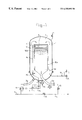
- FIG. 1 shows an example of a membrane gas absorber according to the invention, where ( 1 ) is (the wall of) the pressure vessel which surrounds the chamber ( 2 ); ( 3 a ) is the gas-phase inlet; ( 4 a ) is the gas-phase outlet; ( 5 ) is the membrane unit, in the form of a DAM module according to the international application 91/09668 by Applicant; ( 6 ) is a membrane element in the form of a hollow fibre which defines a feed-through channel ( 7 ); ( 8 a ) is the liquid-phase inlet; ( 9 a ) is the liquid-phase outlet, ( 10 a ) and ( 10 b ) are the “module parts) of the module; ( 11 ), ( 12 ), ( 13 ), ( 17 ) and ( 23 ) are control means which can be shut off, such as a valve, ( 14 ) is a main for supplying the gas stream to the absorber, ( 15 ) is a pressure-dependent control means which can be shut off
- the gas phase is supplied, via supply line ( 3 a ), to chamber ( 2 ) in pressure vessel ( 1 ) which, in the operating position, is essentially arranged vertically.
- the gas flows upwards past the DAM module ( 5 ) and from the top flows downwards through the DAM module ( 5 ) and is discharged via outlet ( 4 a ).
- a liquid phase is supplied via inlet ( 8 a ) to the DAM module ( 5 ), i.e. to the “module part” ( 10 a ) of the module which, in the process, provides for distribution of the liquid stream over the feed-through channels ( 7 ) in the hollow fibres.
- the hollow fibres in the DAM module are essentially located in a horizontal plane perpendicular to the flow direction of the gas stream through the module; the DAM module may comprise a plurality of modules which are connected to one another and whose hollow fibres are at an angle with respect to one another, preferably a perpendicular angle.
- the liquid phase flows through the hollow fibres, around which the gas phase is flowing at the same time, the constituents to be absorbed being absorbed from the gas phase into the liquid phase through the wall of the hollow fibres.
- the liquid phase is then discharged via line ( 9 a ), possibly via a further “module part” ( 10 a ), serving as an outlet, of the DAM module ( 5 ).
- the inlet ( 8 a ) and the outlet ( 9 a ) are connected in such a way to the DAM module ( 5 ) and its “module parts” ( 10 ) serving as an inlet and outlet, that the absorption process takes place as a countercurrent process, in the present case as a result of the liquid phase being supplied to the bottom of the DAM module via inlet ( 8 a ) and being discharged via outlet ( 9 a ) at the top, i.e. where the liquid phase first comes into contact with the gas phase.
- FIG. 2 An alternative embodiment, where the gas outlet ( 4 a ) is located at the top of chamber ( 2 ), is depicted in FIG. 2 .
- the gas phase flows upwards through the DAM module ( 5 ), and liquid inlet ( 8 a ) is located at the top, and liquid outlet ( 9 a ) at the bottom, of the DAM module, to permit countercurrent absorption.
- the “walls” (“module parts”) of the DAM module serve as guide means for guiding the gas stream, both past the outside (first embodiment) and past the inside through the module (first and second embodiments). This also makes it possible to regulate/control the flow of gas phase through chamber ( 2 ) and through the DAM module ( 5 ) and to carry out the process as a pure contercurrent process. It is also possible, however, to dispose further internal guide means in chamber ( 2 ) to permit at least partial recirculation of the gas stream exiting from the module.
- Control of the above-described installation can be implemented, for example, as follows:
- the pressure vessel ( 1 ) there is a gas pressure of, for example, 200 bar.
- the gas enters via the line provided with a valve ( 11 ) and via inlet ( 3 a ) and leaves the pressure vessel ( 1 ) via outlet ( 4 a ) and via a line provided with valve ( 12 ).
- line ( 14 ) will be shut off by means of valve ( 13 ).
- the gas and the CO 2 -absorbing liquid supplied by pump ( 24 ) via inlet ( 8 a ) are separated by membranes. This liquid is pumped from the bottom to the top through the module, so that air in the liquid is not given the chance to put any sections of the module out of action.
- the liquid passes a simple spring-loaded pressure control valve ( 15 ), which is set to 0.5 bar, for example.
- pump ( 24 ) fails, non-return valve ( 18 ) will close, the liquid system remains full, and after some time gas pressure and liquid pressure will be equal. The pump can therefore be stopped at any time. If liquid leaks to outside the module, it ends up in vessel ( 19 ) which is fitted with two electrodes which activate the alarm. In the event of liquid leaking inside the module, it ends up in vessel ( 20 ); this too will result in an alarm.
- the gas phase containing the components it is possible for the gas phase containing the components to be absorbed to be passed through the membrane elements ( 6 ), while the liquid phase flows around the membrane elements ( 6 ) on the outside.
- the membrane elements and consequently the flow direction of the gas phase will be in a plane perpendicular to the flow direction of the liquid phase, to achieve the desired cross-flow, but the membrane elements will preferably be positioned essentially parallel to the axis of the pressure vessel.
- the membrane elements will preferably form a part of a membrane unit which, again, is preferably of modular design.
- This embodiment may be preferable if, depending on the process to be carried out, excessive mass transfer barriers occur in the liquid phase when the liquid phase is passed through the fibres and the gas phase is passed over the fibres as described hereinabove. This may be the case, for example, with certain specific processes for CO 2 absorption.
- this aspect of the invention it is possible to use an apparatus analogous to the above-described apparatus, the liquid phase being supplied to chamber ( 2 ) and passing through membrane module ( 5 ), whilst the gas phase is supplied independently to the membrane elements ( 6 ) and passes through channels ( 7 ).
- this aspect of the invention can be implemented essentially analogously to the abovementioned, as will be obvious to those skilled in the art.
- the gas phase is supplied once more to chamber ( 2 ) which in this arrangement is in gas contact with the feed-through channels ( 7 ) defined by membrane elements ( 6 ).
- the liquid phase is passed through a feed-through channel which is located in membrane unit ( 5 ), is independent of chamber ( 2 ) and is defined/enclosed by (the walls of) the membrane unit ( 5 ).
- the membrane elements ( 6 ) run through this feed-through channel for the liquid phase, the membrane elements ( 6 ) being located in said feed-through channel in such a way that, during operation, there is a cross-flow of the liquid phase against the membrane elements ( 6 ).
- a pressure vessel ( 1 ) which encloses an essentially closed chamber ( 2 );
- the membrane unit ( 5 ) defines at least one essentially closed feed-through chamber ( 10 d ) for the liquid phase, said feed-through chamber being independent of chamber ( 2 );
- membrane unit ( 5 ) comprises at least one membrane element ( 6 ) which runs through the essentially closed feed-through chamber ( 10 d ) and defines a feed-through channel ( 7 ) which is essentially independent of the feed-through chamber ( 10 d );
- membrane element ( 6 ) is effectively connected to chamber ( 2 ) in such a way that the gas phase from chamber ( 2 ) can be passed through feed-through channel ( 7 );
- pressure vessel ( 1 ), inlet ( 3 b ) and outlet ( 4 b ) and in particular membrane unit ( 5 ), membrane elements ( 6 ), inlet ( 8 b ), outlet ( 9 b ) and chamber ( 10 d ) are provided in such a way that the liquid phase can be directed through chamber ( 10 d ) past/over membrane element ( 6 ) in a flow direction essentially perpendicular to the flow direction of the gas phase through membrane element ( 6 ), exchange being able to take place of components to be absorbed between the gas phase and the liquid phase through (the wall of) membrane element ( 6 ).
- the method according to this embodiment of the invention using the above-described apparatus, comprises
- a gas phase comprising the one or more components to be absorbed, via inlet ( 3 b ) and outlet ( 4 b ) through chamber ( 2 ) and feed-through channel ( 7 ) of membrane element ( 6 ), the gas phase having a pressure of more than 4 bar, preferably more than 10 bar, more preferably 50-200 bar;
- FIG. 3 where ( 1 ) is (the wall of) the pressure vessel which surrounds chamber ( 2 ); ( 3 b ) is the gas-phase inlet; ( 4 b ) is the gas-phase outlet; ( 5 ) is the membrane unit; ( 6 ) is a membrane element in the form of a hollow fibre which defines a feed-through channel ( 7 ); ( 8 b ) is the liquid-phase inlet; ( 9 b ) is the liquid-phase outlet, ( 10 c ) is a “module part” of the membrane unit ( 5 ) for distributing the gas stream over the membrane elements ( 6 ), ( 10 d ) are liquid-phase feed-through chambers which are in mutual liquid contact via “module parts” ( 10 e ), and ( 25 ) are guide means, disposed in chamber ( 2 ) for the gas stream.
- the gas phase is supplied, via supply line ( 3 b ), to chamber ( 2 ) and then flows through the feed-through channels ( 7 ), the gas phase being distributed over the membrane elements ( 6 ) by module parts ( 10 c ).
- the gas phase then leaves the membrane module ( 5 ) to arrive in chamber ( 2 ) and is discharged via outlet ( 4 b ).
- the chamber ( 2 ) will, as a rule, be provided with guide means for the gas stream, which ensure that the gas stream can be passed through the feed-through channels ( 7 ) in one direction and as a constant stream.
- these guide means are depicted as baffles ( 25 ).
- a liquid phase is supplied, via inlet ( 8 b ), to the essentially closed feed-through chambers ( 10 d ) and is then discharged via outlet ( 9 b ).
- These feed-through chambers ( 10 d ), which together form an essentially closed feed-through channel through the membrane module ( 5 ) in this arrangement are in liquid contact with one another and with inlet ( 8 b ) and outlet ( 9 b ) via “module parts”.
- the flow of the liquid phase through the feed-through chambers ( 10 d ) in this arrangement is such that essentially there is cross-flow against the hollow fibres ( 6 ).
- the gas phase therefore flows through the hollow fibres ( 6 ), which at the same time have the liquid phase flowing around them, the constituents to be absorbed being absorbed from the gas phase into the liquid phase through the wall of the hollow fibres.
- the inlet ( 8 b ) and the outlet ( 9 b ) are preferably connected in such a way to membrane unit ( 5 ) and feed-through chambers ( 10 d ), that the absorption process can be implemented as a countercurrent process, in the figure as a result of the liquid phase being supplied via inlet ( 8 b ) to that side of the membrane unit ( 5 ) where the gas phase leaves the membrane module ( 5 ).
Applications Claiming Priority (3)
| Application Number | Priority Date | Filing Date | Title |
|---|---|---|---|
| NL1006013 | 1997-05-09 | ||
| NL1006013A NL1006013C2 (nl) | 1997-05-09 | 1997-05-09 | Inrichting en werkwijze voor het uitvoeren van membraan-gas/vloeistofabsorptie bij verhoogde druk. |
| PCT/NL1998/000256 WO1998051399A1 (fr) | 1997-05-09 | 1998-05-07 | Appareil et procede pour realiser une absorption gazeuse et liquide par membrane a une pression elevee |
Publications (1)
| Publication Number | Publication Date |
|---|---|
| US6355092B1 true US6355092B1 (en) | 2002-03-12 |
Family
ID=19764941
Family Applications (1)
| Application Number | Title | Priority Date | Filing Date |
|---|---|---|---|
| US09/423,435 Expired - Lifetime US6355092B1 (en) | 1997-05-09 | 1998-05-07 | Apparatus and method for performing membrane gas/liquid absorption at elevated pressure |
Country Status (14)
| Country | Link |
|---|---|
| US (1) | US6355092B1 (fr) |
| EP (1) | EP0980286B1 (fr) |
| JP (1) | JP2001524875A (fr) |
| CN (1) | CN1255073A (fr) |
| AT (1) | ATE222793T1 (fr) |
| AU (1) | AU7457498A (fr) |
| BR (1) | BR9808753A (fr) |
| DE (1) | DE69807462T2 (fr) |
| DK (1) | DK0980286T3 (fr) |
| ID (1) | ID24604A (fr) |
| NL (1) | NL1006013C2 (fr) |
| NO (1) | NO316057B1 (fr) |
| RU (1) | RU2195359C2 (fr) |
| WO (1) | WO1998051399A1 (fr) |
Cited By (15)
| Publication number | Priority date | Publication date | Assignee | Title |
|---|---|---|---|---|
| WO2002038250A1 (fr) * | 2000-11-08 | 2002-05-16 | Clearwater International, L.L.C. | Deshydratation de gaz effectuee au moyen d'une membrane et d'une solution de formiate de potassium |
| US6497749B2 (en) * | 2001-03-30 | 2002-12-24 | United Technologies Corporation | Dehumidification process and apparatus using collodion membrane |
| US6517607B2 (en) * | 2001-06-04 | 2003-02-11 | Gas Technology Institute | Method and apparatus for selective removal of a condensable component from a process stream with latent heat recovery |
| US20040089152A1 (en) * | 2001-03-28 | 2004-05-13 | Ewald Neumann | Method for the purification of corrosive gases |
| WO2007074126A1 (fr) * | 2005-12-27 | 2007-07-05 | Shell Internationale Research Maatschappij B.V. | Appareil de separation de gaz |
| US20080226525A1 (en) * | 2007-03-13 | 2008-09-18 | Gas Technology Institute | Method for creating a gas-liquid contact area |
| US20080276803A1 (en) * | 2007-05-08 | 2008-11-13 | General Electric Company | Methods and systems for reducing carbon dioxide in combustion flue gases |
| US20100313758A1 (en) * | 2009-06-12 | 2010-12-16 | Co2Crc Technologies Pty Ltd. | Gas absorption membranes and the manufacture thereof |
| US20100325958A1 (en) * | 2009-06-30 | 2010-12-30 | Jennifer Lynn Molaison | Method and Apparatus for Removal of Carbon Dioxide from Pre-Combustion Syngas |
| US20110217787A1 (en) * | 2010-03-02 | 2011-09-08 | Japan Cooperation Center, Petroleum | Concentration measuring apparatus for hydrogen sulfide in gas flow, and method for determining sulfide ion |
| US20120247327A1 (en) * | 2010-09-27 | 2012-10-04 | Conocophillips Company | Hollow-fiber membrane contactors |
| WO2013142325A1 (fr) | 2012-03-22 | 2013-09-26 | Saudi Arabian Oil Company | Procédé d'élimination de mercure d'un courant gazeux ou liquide |
| US20140144323A1 (en) * | 2012-11-23 | 2014-05-29 | Chung Yuan Christian University | Silica-like Membrane for Separating Gas and the method for forming the same |
| CN104593108A (zh) * | 2015-02-17 | 2015-05-06 | 沈阳环境科学研究院 | 含汞天然气泄漏应急处理及清洗含汞设备的集成化装置 |
| RU2570281C1 (ru) * | 2014-08-12 | 2015-12-10 | Дмитрий Юрьевич Мартынов | Газоразделительная теплообменная установка |
Families Citing this family (8)
| Publication number | Priority date | Publication date | Assignee | Title |
|---|---|---|---|---|
| GB2368542B (en) * | 1999-08-12 | 2003-01-08 | Kvaerner Process Systems As | Protection system to prevent damage to a gas diffusion membrane |
| US6926829B2 (en) | 2000-03-06 | 2005-08-09 | Kvaerner Process Systems A.S. | Apparatus and method for separating fluids through a membrane |
| US8057579B2 (en) * | 2008-11-10 | 2011-11-15 | General Electric Company | Method, apparatus, and system for acid gas removal |
| RU2011101428A (ru) | 2011-01-14 | 2012-07-20 | Недерландсе Органисати Вор Тугепаст-Натюрветенсхаппелейк Ондерзук (Тно) (Nl) | Способ и устройство для разделения газовой смеси |
| US9731245B2 (en) * | 2012-09-26 | 2017-08-15 | Dow Corning Corporation | Method of separating a gas using at least one membrane in contact with an organosilicon fluid |
| CN104812465B (zh) * | 2013-06-14 | 2017-03-15 | 江苏优拿大环保科技有限公司 | 基于膜的废气洗涤方法和系统 |
| CN106268380B (zh) * | 2016-09-19 | 2019-07-09 | 石河子大学 | 一种基于甘氨酸钠的聚电解质膜及其制备方法和应用 |
| CN113230861A (zh) * | 2021-04-26 | 2021-08-10 | 杭州电子科技大学 | 一种分级式工业废气处理装置 |
Citations (30)
| Publication number | Priority date | Publication date | Assignee | Title |
|---|---|---|---|---|
| US2506656A (en) * | 1945-10-15 | 1950-05-09 | George S Hills | Air conditioner |
| US3911080A (en) * | 1971-09-10 | 1975-10-07 | Wright H Dudley | Air pollution control |
| US3976451A (en) * | 1974-06-04 | 1976-08-24 | General Electric Company | Vacuum extract system for a membrane oxygen enricher |
| US3981696A (en) * | 1973-05-18 | 1976-09-21 | Commissariat A L'energie Atomique | Multipassage diffuser |
| US4176069A (en) * | 1976-05-21 | 1979-11-27 | Licentia Patent-Verwaltungs-G.M.B.H. | Device for exchanging substances and method of manufacturing the device |
| US4268279A (en) * | 1978-06-15 | 1981-05-19 | Mitsubishi Rayon Co., Ltd. | Gas transfer process with hollow fiber membrane |
| US4497640A (en) * | 1983-02-04 | 1985-02-05 | Compagnie Francaise De Petroles | Process for the dehydration of gases containing hydrocarbons |
| US4606741A (en) * | 1983-08-26 | 1986-08-19 | Compagnie Francaise Des Petroles | Process for purifying natural gas |
| US4750918A (en) | 1985-05-28 | 1988-06-14 | The Trustees Of The Stevens Institute Of Technology | Selective-permeation gas-separation process and apparatus |
| US4834779A (en) * | 1986-10-27 | 1989-05-30 | Liquid Air Corporation | Process for membrane seperation of gas mixtures |
| US4900448A (en) * | 1988-03-29 | 1990-02-13 | Honeywell Inc. | Membrane dehumidification |
| US4915838A (en) * | 1988-03-29 | 1990-04-10 | Honeywell Inc. | Membrane dehumidification |
| JPH02229529A (ja) * | 1989-03-01 | 1990-09-12 | Ngk Insulators Ltd | 流体の分離方法、分離装置および分離膜 |
| US4960520A (en) * | 1989-07-14 | 1990-10-02 | The Regents Of The University Of Minnesota | Method of removing organic volatile and semi-volatile contaminants from an aqueous solution |
| EP0430331A1 (fr) * | 1989-11-23 | 1991-06-05 | Nederlandse Organisatie Voor Toegepast-Natuurwetenschappelijk Onderzoek Tno | Purification d'air |
| WO1991009668A1 (fr) | 1990-01-03 | 1991-07-11 | Nederlandse Organisatie Voor Toegepast-Natuurwetenschappelijk Onderzoek Tno | Dispositif de transfert servant a transferer des matieres et/ou de la chaleur d'un milieu en ecoulement a un autre |
| EP0521495A2 (fr) | 1991-07-05 | 1993-01-07 | Akzo Nobel N.V. | Procédé et appareil de fabrication de modules à fibres creuses |
| EP0524242A1 (fr) | 1990-04-03 | 1993-01-27 | Tno | Procede de separation utilisant une membrane pour deshydrater un melange de gaz, de vapeur ou de liquides par evaporation a travers une membrane ou par permeation de vapeur. |
| US5328610A (en) * | 1993-06-15 | 1994-07-12 | Integrated Process Technologies | Self-supported low pressure drop hollow fiber membrane panel and contactor module |
| DE4308697A1 (de) | 1993-03-18 | 1994-09-22 | Durst Franz Prof Dr Dr H C | Verfahren zur Anreicherung eines ersten gasförmigen oder flüssigen Mediums mit einem zweiten Gas oder einer zweiten Flüssigkeit sowie ein Reaktor zur Durchführung des Verfahrens |
| WO1995026225A1 (fr) | 1994-03-25 | 1995-10-05 | Nederlandse Organisatie Voor Toegepast-Natuurwetenschappelijk Onderzoek Tno | Procede d'absorption de gaz au travers d'une membrane |
| WO1995035153A2 (fr) | 1994-06-22 | 1995-12-28 | Fls Miljø A/S | Procede et appareil de transfert de masse |
| US5482859A (en) * | 1990-08-28 | 1996-01-09 | Biller; Edmund | Method and device for feeding gaseous substances into liquid media |
| US5498339A (en) * | 1993-07-15 | 1996-03-12 | Dsm N.V. | Process and device for the separation of an unsaturated hydrocarbon from a fluid mixture with other hydrocarbons |
| US5525144A (en) * | 1995-04-20 | 1996-06-11 | A/G Technology Corporation | Tangential flow filtering and separating |
| EP0871535A1 (fr) | 1995-07-07 | 1998-10-21 | Nederlandse Organisatie voor Toegepast Natuurwetenschappelijk Onderzoek TNO | Procede pour absorption de constituants gazeux oxydables ou reductibles a travers une membrane |
| US5876486A (en) * | 1995-09-09 | 1999-03-02 | Dornier Gmbh | Method and apparatus for removing carbon dioxide |
| US5888273A (en) * | 1996-09-25 | 1999-03-30 | Buxbaum; Robert E. | High temperature gas purification system |
| US5954858A (en) * | 1995-11-22 | 1999-09-21 | North Carolina State University | Bioreactor process for the continuous removal of organic compounds from a vapor phase process stream |
| US6156096A (en) * | 1994-03-23 | 2000-12-05 | Applied Membrane Technology, Inc. | Gas separation using hollow fiber contained liquid membrane |
-
1997
- 1997-05-09 NL NL1006013A patent/NL1006013C2/nl not_active IP Right Cessation
-
1998
- 1998-05-07 DE DE69807462T patent/DE69807462T2/de not_active Expired - Lifetime
- 1998-05-07 CN CN98804921.XA patent/CN1255073A/zh active Pending
- 1998-05-07 BR BR9808753-3A patent/BR9808753A/pt not_active IP Right Cessation
- 1998-05-07 US US09/423,435 patent/US6355092B1/en not_active Expired - Lifetime
- 1998-05-07 AU AU74574/98A patent/AU7457498A/en not_active Abandoned
- 1998-05-07 AT AT98921921T patent/ATE222793T1/de not_active IP Right Cessation
- 1998-05-07 JP JP54907598A patent/JP2001524875A/ja not_active Ceased
- 1998-05-07 RU RU99126430/12A patent/RU2195359C2/ru not_active IP Right Cessation
- 1998-05-07 EP EP98921921A patent/EP0980286B1/fr not_active Expired - Lifetime
- 1998-05-07 WO PCT/NL1998/000256 patent/WO1998051399A1/fr active IP Right Grant
- 1998-05-07 ID IDW991320A patent/ID24604A/id unknown
- 1998-05-07 DK DK98921921T patent/DK0980286T3/da active
-
1999
- 1999-11-05 NO NO19995414A patent/NO316057B1/no not_active IP Right Cessation
Patent Citations (31)
| Publication number | Priority date | Publication date | Assignee | Title |
|---|---|---|---|---|
| US2506656A (en) * | 1945-10-15 | 1950-05-09 | George S Hills | Air conditioner |
| US3911080A (en) * | 1971-09-10 | 1975-10-07 | Wright H Dudley | Air pollution control |
| US3981696A (en) * | 1973-05-18 | 1976-09-21 | Commissariat A L'energie Atomique | Multipassage diffuser |
| US3976451A (en) * | 1974-06-04 | 1976-08-24 | General Electric Company | Vacuum extract system for a membrane oxygen enricher |
| US4176069A (en) * | 1976-05-21 | 1979-11-27 | Licentia Patent-Verwaltungs-G.M.B.H. | Device for exchanging substances and method of manufacturing the device |
| US4268279A (en) * | 1978-06-15 | 1981-05-19 | Mitsubishi Rayon Co., Ltd. | Gas transfer process with hollow fiber membrane |
| US4497640A (en) * | 1983-02-04 | 1985-02-05 | Compagnie Francaise De Petroles | Process for the dehydration of gases containing hydrocarbons |
| US4606741A (en) * | 1983-08-26 | 1986-08-19 | Compagnie Francaise Des Petroles | Process for purifying natural gas |
| US4750918A (en) | 1985-05-28 | 1988-06-14 | The Trustees Of The Stevens Institute Of Technology | Selective-permeation gas-separation process and apparatus |
| US4834779A (en) * | 1986-10-27 | 1989-05-30 | Liquid Air Corporation | Process for membrane seperation of gas mixtures |
| US4900448A (en) * | 1988-03-29 | 1990-02-13 | Honeywell Inc. | Membrane dehumidification |
| US4915838A (en) * | 1988-03-29 | 1990-04-10 | Honeywell Inc. | Membrane dehumidification |
| JPH02229529A (ja) * | 1989-03-01 | 1990-09-12 | Ngk Insulators Ltd | 流体の分離方法、分離装置および分離膜 |
| US4960520A (en) * | 1989-07-14 | 1990-10-02 | The Regents Of The University Of Minnesota | Method of removing organic volatile and semi-volatile contaminants from an aqueous solution |
| EP0430331A1 (fr) * | 1989-11-23 | 1991-06-05 | Nederlandse Organisatie Voor Toegepast-Natuurwetenschappelijk Onderzoek Tno | Purification d'air |
| EP0509031A1 (fr) | 1990-01-03 | 1992-10-21 | Tno | Dispositif de transfert servant a transferer des matieres et/ou de la chaleur d'un milieu en ecoulement a un autre. |
| WO1991009668A1 (fr) | 1990-01-03 | 1991-07-11 | Nederlandse Organisatie Voor Toegepast-Natuurwetenschappelijk Onderzoek Tno | Dispositif de transfert servant a transferer des matieres et/ou de la chaleur d'un milieu en ecoulement a un autre |
| EP0524242A1 (fr) | 1990-04-03 | 1993-01-27 | Tno | Procede de separation utilisant une membrane pour deshydrater un melange de gaz, de vapeur ou de liquides par evaporation a travers une membrane ou par permeation de vapeur. |
| US5482859A (en) * | 1990-08-28 | 1996-01-09 | Biller; Edmund | Method and device for feeding gaseous substances into liquid media |
| EP0521495A2 (fr) | 1991-07-05 | 1993-01-07 | Akzo Nobel N.V. | Procédé et appareil de fabrication de modules à fibres creuses |
| DE4308697A1 (de) | 1993-03-18 | 1994-09-22 | Durst Franz Prof Dr Dr H C | Verfahren zur Anreicherung eines ersten gasförmigen oder flüssigen Mediums mit einem zweiten Gas oder einer zweiten Flüssigkeit sowie ein Reaktor zur Durchführung des Verfahrens |
| US5328610A (en) * | 1993-06-15 | 1994-07-12 | Integrated Process Technologies | Self-supported low pressure drop hollow fiber membrane panel and contactor module |
| US5498339A (en) * | 1993-07-15 | 1996-03-12 | Dsm N.V. | Process and device for the separation of an unsaturated hydrocarbon from a fluid mixture with other hydrocarbons |
| US6156096A (en) * | 1994-03-23 | 2000-12-05 | Applied Membrane Technology, Inc. | Gas separation using hollow fiber contained liquid membrane |
| WO1995026225A1 (fr) | 1994-03-25 | 1995-10-05 | Nederlandse Organisatie Voor Toegepast-Natuurwetenschappelijk Onderzoek Tno | Procede d'absorption de gaz au travers d'une membrane |
| WO1995035153A2 (fr) | 1994-06-22 | 1995-12-28 | Fls Miljø A/S | Procede et appareil de transfert de masse |
| US5525144A (en) * | 1995-04-20 | 1996-06-11 | A/G Technology Corporation | Tangential flow filtering and separating |
| EP0871535A1 (fr) | 1995-07-07 | 1998-10-21 | Nederlandse Organisatie voor Toegepast Natuurwetenschappelijk Onderzoek TNO | Procede pour absorption de constituants gazeux oxydables ou reductibles a travers une membrane |
| US5876486A (en) * | 1995-09-09 | 1999-03-02 | Dornier Gmbh | Method and apparatus for removing carbon dioxide |
| US5954858A (en) * | 1995-11-22 | 1999-09-21 | North Carolina State University | Bioreactor process for the continuous removal of organic compounds from a vapor phase process stream |
| US5888273A (en) * | 1996-09-25 | 1999-03-30 | Buxbaum; Robert E. | High temperature gas purification system |
Cited By (28)
| Publication number | Priority date | Publication date | Assignee | Title |
|---|---|---|---|---|
| WO2002038250A1 (fr) * | 2000-11-08 | 2002-05-16 | Clearwater International, L.L.C. | Deshydratation de gaz effectuee au moyen d'une membrane et d'une solution de formiate de potassium |
| US20040089152A1 (en) * | 2001-03-28 | 2004-05-13 | Ewald Neumann | Method for the purification of corrosive gases |
| US7108737B2 (en) * | 2001-03-28 | 2006-09-19 | Basf Aktiengesellschaft | Method for the purification of corrosive gases |
| US6497749B2 (en) * | 2001-03-30 | 2002-12-24 | United Technologies Corporation | Dehumidification process and apparatus using collodion membrane |
| US6517607B2 (en) * | 2001-06-04 | 2003-02-11 | Gas Technology Institute | Method and apparatus for selective removal of a condensable component from a process stream with latent heat recovery |
| US20100218675A1 (en) * | 2005-12-27 | 2010-09-02 | Andre Buijs | Gas separation apparatus |
| WO2007074126A1 (fr) * | 2005-12-27 | 2007-07-05 | Shell Internationale Research Maatschappij B.V. | Appareil de separation de gaz |
| US20080226525A1 (en) * | 2007-03-13 | 2008-09-18 | Gas Technology Institute | Method for creating a gas-liquid contact area |
| US7544340B2 (en) | 2007-03-13 | 2009-06-09 | Gas Technology Institute | Method for creating a gas-liquid contact area |
| US20080276803A1 (en) * | 2007-05-08 | 2008-11-13 | General Electric Company | Methods and systems for reducing carbon dioxide in combustion flue gases |
| AU2008201861B2 (en) * | 2007-05-08 | 2012-12-06 | Bha Altair, Llc | Methods and systems for reducing carbon dioxide in combustion flue gases |
| CN101301562B (zh) * | 2007-05-08 | 2013-11-20 | 通用电气公司 | 用于降低燃烧烟气中二氧化碳的方法和系统 |
| US8398743B2 (en) * | 2007-05-08 | 2013-03-19 | General Electric Company | Methods and systems for reducing carbon dioxide in combustion flue gases |
| GB2449165B (en) * | 2007-05-08 | 2012-04-25 | Gen Electric | Methods and systems for reducing carbon dioxide in combustion flue gases |
| US20100313758A1 (en) * | 2009-06-12 | 2010-12-16 | Co2Crc Technologies Pty Ltd. | Gas absorption membranes and the manufacture thereof |
| US8202349B2 (en) * | 2009-06-30 | 2012-06-19 | General Electric Company | Method and apparatus for removal of carbon dioxide from pre-combustion syngas |
| US20100325958A1 (en) * | 2009-06-30 | 2010-12-30 | Jennifer Lynn Molaison | Method and Apparatus for Removal of Carbon Dioxide from Pre-Combustion Syngas |
| GB2471550B (en) * | 2009-06-30 | 2014-03-19 | Gen Electric | Method and apparatus for removal of carbon dioxide from pre-combustion syngas |
| US20110217787A1 (en) * | 2010-03-02 | 2011-09-08 | Japan Cooperation Center, Petroleum | Concentration measuring apparatus for hydrogen sulfide in gas flow, and method for determining sulfide ion |
| US8709820B2 (en) * | 2010-03-02 | 2014-04-29 | Japan Cooperation Center, Petroleum | Concentration measuring apparatus for hydrogen sulfide in gas flow, and method for determining sulfide ion |
| US20120247327A1 (en) * | 2010-09-27 | 2012-10-04 | Conocophillips Company | Hollow-fiber membrane contactors |
| WO2013142325A1 (fr) | 2012-03-22 | 2013-09-26 | Saudi Arabian Oil Company | Procédé d'élimination de mercure d'un courant gazeux ou liquide |
| US8641890B2 (en) | 2012-03-22 | 2014-02-04 | Saudi Arabian Oil Company | Method for removing mercury from a gaseous or liquid stream |
| JP2015514002A (ja) * | 2012-03-22 | 2015-05-18 | サウジ アラビアン オイル カンパニー | ガス流または液体流から水銀を除去するための方法 |
| US20140144323A1 (en) * | 2012-11-23 | 2014-05-29 | Chung Yuan Christian University | Silica-like Membrane for Separating Gas and the method for forming the same |
| US9101885B2 (en) * | 2012-11-23 | 2015-08-11 | Chung-Yuan Christian University | Silica-like membrane for separating gas and the method for forming the same |
| RU2570281C1 (ru) * | 2014-08-12 | 2015-12-10 | Дмитрий Юрьевич Мартынов | Газоразделительная теплообменная установка |
| CN104593108A (zh) * | 2015-02-17 | 2015-05-06 | 沈阳环境科学研究院 | 含汞天然气泄漏应急处理及清洗含汞设备的集成化装置 |
Also Published As
| Publication number | Publication date |
|---|---|
| DK0980286T3 (da) | 2002-12-30 |
| EP0980286B1 (fr) | 2002-08-28 |
| NO316057B1 (no) | 2003-12-08 |
| DE69807462T2 (de) | 2003-05-15 |
| NO995414L (no) | 2000-01-07 |
| ATE222793T1 (de) | 2002-09-15 |
| NO995414D0 (no) | 1999-11-05 |
| WO1998051399A1 (fr) | 1998-11-19 |
| JP2001524875A (ja) | 2001-12-04 |
| ID24604A (id) | 2000-07-27 |
| EP0980286A1 (fr) | 2000-02-23 |
| AU7457498A (en) | 1998-12-08 |
| DE69807462D1 (de) | 2002-10-02 |
| CN1255073A (zh) | 2000-05-31 |
| NL1006013C2 (nl) | 1998-11-10 |
| RU2195359C2 (ru) | 2002-12-27 |
| BR9808753A (pt) | 2000-07-11 |
Similar Documents
| Publication | Publication Date | Title |
|---|---|---|
| US6355092B1 (en) | Apparatus and method for performing membrane gas/liquid absorption at elevated pressure | |
| US11110388B2 (en) | Apparatus and system for swing adsorption processes related thereto | |
| RU2716686C1 (ru) | Устройство и система для осуществления процессов короткоцикловой адсорбции | |
| CA2972705C (fr) | Separation des impuretes d'un flux fluidique au moyen de plusieurs contacteurs a co-courant | |
| US7481988B2 (en) | Method for obtaining a high pressure acid gas stream by removal of the acid gases from a fluid stream | |
| AU2013224145B2 (en) | Gas treatment system using supersonic separators | |
| EA025413B1 (ru) | Способ и система для обработки газового потока | |
| EA025720B1 (ru) | Способ короткоцикловой адсорбции при переменном давлении и температуре | |
| JP6231975B2 (ja) | 天然ガス精製システム | |
| NO20171259A1 (en) | Subsea fluid processing system | |
| ITPI20110018A1 (it) | Metodo e apparato per l'addolcimento e/o la disidratazione di un gas a base di idrocarburi, in particolare gas naturale | |
| EP1647531A1 (fr) | procede de concentration de methane a partir de boues residuaires et equipements de stockage de methane | |
| AU2016317387B2 (en) | Process and system for swing adsorption using an overhead stream of a demethanizer as purge gas | |
| RU2760529C1 (ru) | Адсорбер | |
| Anderson et al. | Case study: membrane CO2 removal from natural gas, Grissik gas plant, Sumatra, Indonesia | |
| AU2014377721B2 (en) | A system and a process for enhancing efficiency of CO2 removal from natural gas stream | |
| RU2754851C1 (ru) | Адсорбер | |
| US11738302B1 (en) | Method of generating renewable natural gas | |
| AU2018256480B2 (en) | Process and system for treating natural gas feedstock | |
| RU2757132C1 (ru) | Блок комплексной очистки воздуха | |
| EP2043762A2 (fr) | Système et méthode de diagnostic et de localisation de panne pour système de régénération d'amines | |
| EP3344368A1 (fr) | Procédé et système pour adsorption modulée au moyen d'un flux de tête d'un déméthaniseur comme gaz de purge | |
| Ciccarelli et al. | Sour Fields Development: New Bulk Removal Technologies |
Legal Events
| Date | Code | Title | Description |
|---|---|---|---|
| AS | Assignment |
Owner name: NEDERLANDSE ORGAISATIE VOOR TOEGEPAST-NATUURWETENS Free format text: ASSIGNMENT OF ASSIGNORS INTEREST;ASSIGNORS:JANSEN, ALBERT EDWARD;FERON, PAUL HUBERT MARIA;HANEMAAIJER, JAN HENDRIK;AND OTHERS;REEL/FRAME:010743/0907 Effective date: 19991026 |
|
| AS | Assignment |
Owner name: NEDERLANDSE ORGANISATIE VOOR TOEGEPAST-NATUURWETEN Free format text: ASSIGNMENT OF ASSIGNORS INTEREST;ASSIGNORS:JANSEN, ALBERT EDWARD;FERON, PAUL HUBERT MARIA;HANEMAAIJER, JAN HENDRIK;AND OTHERS;REEL/FRAME:012554/0233 Effective date: 19991026 |
|
| STCF | Information on status: patent grant |
Free format text: PATENTED CASE |
|
| FPAY | Fee payment |
Year of fee payment: 4 |
|
| FPAY | Fee payment |
Year of fee payment: 8 |
|
| FPAY | Fee payment |
Year of fee payment: 12 |