US6253787B1 - Fluid flow and pressure control system and method - Google Patents
Fluid flow and pressure control system and method Download PDFInfo
- Publication number
- US6253787B1 US6253787B1 US09/316,579 US31657999A US6253787B1 US 6253787 B1 US6253787 B1 US 6253787B1 US 31657999 A US31657999 A US 31657999A US 6253787 B1 US6253787 B1 US 6253787B1
- Authority
- US
- United States
- Prior art keywords
- housing
- fluid
- shuttle
- choke member
- choke
- Prior art date
- Legal status (The legal status is an assumption and is not a legal conclusion. Google has not performed a legal analysis and makes no representation as to the accuracy of the status listed.)
- Expired - Lifetime
Links
- 239000012530 fluid Substances 0.000 title claims abstract description 91
- 238000000034 method Methods 0.000 title abstract description 8
- 230000004044 response Effects 0.000 claims description 4
- 238000005553 drilling Methods 0.000 description 30
- 230000015572 biosynthetic process Effects 0.000 description 5
- 239000007789 gas Substances 0.000 description 5
- 125000006850 spacer group Chemical group 0.000 description 4
- 238000013461 design Methods 0.000 description 2
- 230000000694 effects Effects 0.000 description 2
- 230000002706 hydrostatic effect Effects 0.000 description 2
- 230000000717 retained effect Effects 0.000 description 2
- 230000000740 bleeding effect Effects 0.000 description 1
- 230000008859 change Effects 0.000 description 1
- 238000004891 communication Methods 0.000 description 1
- 238000001816 cooling Methods 0.000 description 1
- 238000005520 cutting process Methods 0.000 description 1
- 238000012423 maintenance Methods 0.000 description 1
- 238000012986 modification Methods 0.000 description 1
- 230000004048 modification Effects 0.000 description 1
- 239000003129 oil well Substances 0.000 description 1
- 238000012545 processing Methods 0.000 description 1
- 150000003839 salts Chemical class 0.000 description 1
- 230000003068 static effect Effects 0.000 description 1
- 238000006467 substitution reaction Methods 0.000 description 1
- 238000011144 upstream manufacturing Methods 0.000 description 1
- 238000013022 venting Methods 0.000 description 1
- XLYOFNOQVPJJNP-UHFFFAOYSA-N water Substances O XLYOFNOQVPJJNP-UHFFFAOYSA-N 0.000 description 1
Images


Classifications
-
- E—FIXED CONSTRUCTIONS
- E21—EARTH OR ROCK DRILLING; MINING
- E21B—EARTH OR ROCK DRILLING; OBTAINING OIL, GAS, WATER, SOLUBLE OR MELTABLE MATERIALS OR A SLURRY OF MINERALS FROM WELLS
- E21B21/00—Methods or apparatus for flushing boreholes, e.g. by use of exhaust air from motor
- E21B21/10—Valve arrangements in drilling-fluid circulation systems
- E21B21/106—Valve arrangements outside the borehole, e.g. kelly valves
-
- F—MECHANICAL ENGINEERING; LIGHTING; HEATING; WEAPONS; BLASTING
- F16—ENGINEERING ELEMENTS AND UNITS; GENERAL MEASURES FOR PRODUCING AND MAINTAINING EFFECTIVE FUNCTIONING OF MACHINES OR INSTALLATIONS; THERMAL INSULATION IN GENERAL
- F16K—VALVES; TAPS; COCKS; ACTUATING-FLOATS; DEVICES FOR VENTING OR AERATING
- F16K47/00—Means in valves for absorbing fluid energy
- F16K47/04—Means in valves for absorbing fluid energy for decreasing pressure or noise level, the throttle being incorporated in the closure member
-
- Y—GENERAL TAGGING OF NEW TECHNOLOGICAL DEVELOPMENTS; GENERAL TAGGING OF CROSS-SECTIONAL TECHNOLOGIES SPANNING OVER SEVERAL SECTIONS OF THE IPC; TECHNICAL SUBJECTS COVERED BY FORMER USPC CROSS-REFERENCE ART COLLECTIONS [XRACs] AND DIGESTS
- Y10—TECHNICAL SUBJECTS COVERED BY FORMER USPC
- Y10T—TECHNICAL SUBJECTS COVERED BY FORMER US CLASSIFICATION
- Y10T137/00—Fluid handling
- Y10T137/7722—Line condition change responsive valves
- Y10T137/7781—With separate connected fluid reactor surface
- Y10T137/7835—Valve seating in direction of flow
Definitions
- the invention relates to a system and method for controlling the flow and pressure of fluid, and, more particularly, to such a system and method according to which a choke is provided that automatically moves to control the flow of fluid in a system and to maintain a desired back pressure on the fluid no matter what flow conditions exist or occur within the system.
- a back pressure control device is mounted in the return flow line for the drilling fluid.
- Back pressure control devices are also necessary for controlling “kicks” in the system caused by the intrusion of salt water or formation gases into the drilling fluid which may lead to a blowout condition. In these situations, sufficient additional back pressure must be imposed on the drilling fluid such that the formation fluid is contained and the well controlled until heavier fluid or mud can be circulated down the drill string and up the annulus to kill the well. It is also desirable to avoid the creation of excessive back pressures which could cause drill string to stick, or cause damage to the formation, the well casing, or the well head equipment.
- U.S. Pat. No. 4,355,784 assigned to the assignee of the present application, discloses an apparatus and method for controlling back pressure of drilling fluid in the above environment which addresses the problems set forth above.
- a balanced choke device moves in a housing to control the flow and the back pressure of the drilling fluid.
- One end of the choke device is exposed to the pressure of the drilling fluid and its other end is exposed to the pressure of a control fluid.
- the choke device moves from its closed position to an open position in response to either an increase in the well fluid pressure or a decrease in the control fluid pressure, it often moves too quickly and too far, thus often overshooting its normal operating position. This can cause pressure spikes and/or can allow a large volume of gas near the surface of the well to vent out of the device, both of which are undesirable.
- a system and method are provided according to which an inlet passage and an outlet passage are formed in a housing and a choke member is movable in the housing to control the flow of fluid from the inlet passage to the outlet passage and to exert a back pressure on the fluid.
- the movement of the choke member from a fully closed position to an open position is dampened.
- the choke device operates automatically to maintain a predetermined back pressure on the flowing fluid despite changes in fluid conditions. Also, highly accurate control of the back pressure at desired pressure values during shutting and opening of fluid flow through the system is achieved. Further, large pressure spikes and/or initial surges of the fluid when the choke device moves from a closed position to an open position are eliminated.
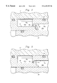
- FIGS. 1-3 and 4 are cross sectional views of the system according to an embodiment of the invention, showing different operational modes.
- FIG. 2 is an enlarged view of a portion of FIG. 1 .
- FIG. 5 is a view similar to FIG. 2 but depicting an alternate embodiment of the present invention.
- the reference numeral 10 refers, in general, to a back pressure control system according to an embodiment of the present invention.
- the system 10 includes a housing 12 having an axial bore 14 extending through its length and having a discharge end 14 a .
- a radially extending inlet passage 16 is also formed in the housing 12 and intersects the bore 14 .
- connecting flanges, or the like, can be provided at the discharge end 14 a of the bore 14 and at the inlet end of the passage 16 to connect them to appropriate flow lines. Drilling fluid from a downhole well is introduced into the inlet passage 16 , passes through the housing 12 and normally discharges from the discharge end of the bore 14 for recirculation.
- a bonnet 18 is secured to the end of the housing 12 opposite the discharge end 14 a of the bore 14 .
- the bonnet 18 is substantially T-shaped in cross section and has a cylindrical portion 18 a extending into the bore 14 of the housing.
- a seal ring 19 extends in a groove formed in an outer surface of the bonnet portional 8 a and engages a corresponding inner surface of the housing 12 .
- the bonnet 18 also includes a cross portion 18 b that extends perpendicular to the cylindrical portion 18 a and is fastened to the corresponding end of the housing 12 in any conventional manner.
- a mandrel 20 is secured in the end portion of the bonnet 18 , and a seal ring 22 extends between the outer surface of the mandrel and the corresponding inner surface of the bonnet.
- a rod 30 is slidably mounted in an axial bore extending through the mandrel 20 , and a seal ring 32 extends in a groove formed in the inner surface of the mandrel defining the latter bore.
- the seal ring 32 engages the outer surface of the rod 30 as the rod slides in the bore of the mandrel 20 under conditions to be described.
- One end portion of the rod 30 projects from the corresponding ends of the mandrel 20 and the bonnet 18 , and the other end portion of the rod 30 projects from the other end of the mandrel 20 and into the bore 14 .
- a spacer 34 is mounted on the latter end of the rod 30 in any known manner and is captured between two snap rings 35 a and 35 b whose function will be described in detail later.
- a cylindrical choke member 36 is disposed in the bore 14 with one end abutting the spacer 34 .
- the choke member 36 is shown in its fully closed position in FIG. 1 and extends in the intersection of the bore 14 with the inlet passage 16 to control the flow of fluid from the latter to the former, as will be described.
- a cylindrical shuttle 40 is slidably mounted over the mandrel 20 , and a seal ring 42 extends in a groove formed in an outer surface of the mandrel and engages a corresponding inner surface of the shuttle. Similarly, a seal ring 44 extends in a groove formed in an outer surface of the shuttle 40 and engages a corresponding inner surface of the housing 12 .
- the shuttle 40 has a reduced-diameter portion 40 a that defines, with the inner surface of the housing 12 , a fluid chamber 46 a .
- Another fluid chamber 46 b is defined between the outer surface of the mandrel 20 and the corresponding inner surface of the bonnet portion 18 a .
- the chambers 46 a and 46 b communicate and receive a control fluid from a passage 48 a formed through the bonnet 18 .
- the passage 48 a is connected to a hydraulic system (not shown) for circulating the control fluid into and from the passage.
- the control fluid is introduced into the passage 48 a , and therefore the chambers 46 a and 46 b , at a predetermined, desired set point pressure as determined by a set point pressure regulator and measured by a gauge located on an associated console. Since the pressure regulator, the gauge and the console are conventional they are not shown and will not be described in any further detail.
- the control fluid enters the chambers 46 a and 46 b and acts against the corresponding exposed end portions of the shuttle 40 .
- the shuttle 40 is designed to move so the force caused by the pressure of the control fluid from the chambers 46 a and 46 b at the predetermined set point pressure acting on the corresponding exposed end portions of the shuttle is equal to the force caused by the pressure of the drilling fluid in the passage 16 acting on the corresponding exposed end portions of the other end of the shuttle and the retainer 50 .
- the shuttle 40 is normally in a balanced condition as will be described.
- a passage 48 b is also formed through the bonnet portion 18 for bleeding air from the system through a bleed valve, or the like (not shown) before operation.
- the shuttle 40 has an externally threaded, reduced-diameter, end portion 40 b which extends over a portion of the choke member 36 .
- a seal ring 49 extends in a groove formed in an inner surface of the end portion 40 b and engages a corresponding outer surface of the choke member 36 .
- An internally threaded trim nut 50 threadedly engages the end portion 40 b of the shuttle 40 and extends over an annular flange 36 a formed on the choke member 36 , to capture the choke member on the shuttle.
- the shuttle 40 also has two spaced grooves formed in its inner diameter for receiving the snap rings 35 a and 35 b . Therefore, axial movement of the shuttle 40 over the fixed mandrel 20 under conditions to be described, causes corresponding axial movement of the choke member 36 , and therefore the spacer 34 and the rod 30 .
- Two cylindrical liners 54 a and 54 b are provided in the bore 14 downstream of its intersection with the passage 16 .
- a choke seat 56 is also disposed in the bore upstream from the liner 54 b , and a seal ring 58 extends in a groove formed in the outer surface of the choke seat and engages a corresponding portion of the inner surface of the housing 12 .
- the choke seat 56 and therefore the liners 54 a and 54 b , are retained in the bore 14 by a static trim member 60 which is retained in a groove formed in the inner surface of the housing 12 by snap ring 61 .
- the liners 54 a and 54 b and the choke seat 56 define a discharge passage 62 in the bore 14 of the housing 12 extending from the intersection of the bore 14 and the passage 16 to the discharge end 14 a of the bore 14 .
- the internal diameter of the choke seat 56 is sized relative to the outer diameter of the choke member 36 to receive same in a relatively tight fit, as will be described.
- the end portion of the shuttle portion 40 a is stepped down to a smaller diameter, and a washer 66 butts against the shoulder thus formed.
- a snap ring 68 extends in an annular groove formed in the latter end portion and retains the washer 66 against the shoulder.
- the outer radial portion of the washer 66 projects radially outwardly from the outer surface of the shuttle portion 40 a .
- An annular lip 18 c extends radially inwardly from the end portion of the bonnet portion 18 a and is sized to define a restricted space between it and the washer, yet permit the washer to pass though the lip with a relatively small clearance.
- the washer 66 passes through the circular space defined by the lip 18 c . Since the control fluid is present in the annular space between the outer surface of the washer 66 and the inner surface of the lip 18 c the latter movement of the shuttle 40 is dampened, i.e. a dashpot effect is created. This prevents excessively quick movement of the shuttle 40 for reasons to be described.
- the choke member 36 In operation, it will be assumed that the choke member 36 is in its maximum open position shown in FIG. 3 . In this position, the “throttling” area, that is, the area between the end of the choke member 36 and the choke seat 56 , is greater than the area of the discharge passage 62 . Thus, there is no back pressure imparted to the drilling fluid as it passes through the inlet passage 16 and the discharge passage 62 and discharges from the housing 12 for recirculation.
- control fluid from the external source described above is introduced, at the above-mentioned predetermined set point pressure, into the passage 48 a and thus passes into the chambers 46 a and 46 b .
- the effective opening, or passage, between the inlet passage 16 and the discharge passage 62 is controlled by the axial movement of the choke member 36 relative to the choke seat 56 .
- the design is such that the set point pressure moves the choke member from the maximum open position of FIG. 3 towards a standard operating position shown in FIG. 4 .
- the choke member 36 throttles the fluid in the inlet passage 16 , thus creating a back pressure on the latter fluid that extends back through the well bore. This occurs until a fluid pressure is present in inlet passage 16 that acts on the corresponding end of the shuttle 40 with the same force as imposed on the other end of the shuttle by the pressure of the control fluid in the chambers 46 a and 46 b .
- This balanced condition of the choke member 36 is the standard operating position shown in FIG. 4 . In this position, a very small gap is maintained between the corresponding ends of the choke member 36 and the seat 56 which allows a relative small amount of the drilling fluid to pass into the discharge chamber 62 while maintaining the above-mentioned back pressure.
- any changes in the condition of the drilling fluid (such as circulating rate, density, and temperature), resulting in corresponding changes in the pressure of the latter fluid acting on the shuttle, causes the shuttle to move accordingly until the balanced condition is reestablished.
- the system 10 establishes and maintains a predetermined back pressure on the drilling fluid despite changes in its characteristics.
- the shuttle 40 and therefore the choke member 36
- This drives the shuttle 40 , and therefore the choke member 36 , in a direction from right-to-left as viewed in the drawings until the choke reaches its fully closed position in which fluid flow from the inlet passage 16 to the discharge passage 12 is blocked.
- the pressure of the control fluid in the chambers 46 a and 46 b is reduced to the predetermined set point value (or the pressure of the drilling fluid in the inlet passage 16 is increased).
- This causes the shuttle 40 to move in a direction from left-to-right as viewed in the drawings thus communicating the inlet passage 16 with the discharge passage 62 and causing the drilling fluid to flow from the former to the latter.
- This latter flow will decrease the pressure of the drilling fluid until it equals the set point pressure of the control fluid in the chambers 46 a and 46 b and the system is in its standard, balanced operating position as described above.
- the console control system automatically feeds or takes fluid from the system 10 to allow the shuttle 40 to move to the appropriate position to control the set point pressure.
- the choke member 36 moves, or is moved, to its closed position of FIG. 1 to terminate all flow through the housing 12 .
- the system 10 operates automatically to maintain a predetermined back pressure on the drilling fluid despite changes in fluid conditions. Also, highly accurate control of the back pressure at desired pressure values during the above-described shutting and opening of the choke member 36 is achieved. Further, as emphasized above, any pressure spikes and/or initial surges of the drilling fluid when the choke member 36 moves from a closed position to an open position are reduced. Still further, any debris that would tend to plug the passage 16 will increase the pressure of the drilling fluid and cause the shuttle 40 , and therefore the choke member 36 , to move to increase the communication between the two passages, maintain the latter pressure at the set point pressure, and cause at least a portion of the debris to release. Also, the size of the washer 66 or the shuttle portion 40 c can be varied to vary the dampening characteristics accordingly.
- the present invention is not limited to the processing of drilling fluid in an oil field environment but is equally applicable to any application involving the control of fluid flow and the applying of a back pressure to same.
Landscapes
- Engineering & Computer Science (AREA)
- Geology (AREA)
- General Engineering & Computer Science (AREA)
- Mechanical Engineering (AREA)
- Life Sciences & Earth Sciences (AREA)
- Mining & Mineral Resources (AREA)
- Geochemistry & Mineralogy (AREA)
- Environmental & Geological Engineering (AREA)
- General Life Sciences & Earth Sciences (AREA)
- Physics & Mathematics (AREA)
- Fluid Mechanics (AREA)
- Fluid-Pressure Circuits (AREA)
- Pipe Accessories (AREA)
- Flow Control (AREA)
- Details Of Valves (AREA)
- Drilling And Boring (AREA)
- Electrical Discharge Machining, Electrochemical Machining, And Combined Machining (AREA)
- Paper (AREA)
- Earth Drilling (AREA)
- Feeding And Controlling Fuel (AREA)
- Control Of Fluid Pressure (AREA)
Priority Applications (22)
| Application Number | Priority Date | Filing Date | Title |
|---|---|---|---|
| US09/316,579 US6253787B1 (en) | 1999-05-21 | 1999-05-21 | Fluid flow and pressure control system and method |
| PCT/US2000/011404 WO2000071919A1 (en) | 1999-05-21 | 2000-04-28 | Fluid flow and pressure control system and method |
| BR0011287A BR0011287A (pt) | 1999-05-21 | 2000-04-28 | Sistema e método para controle de fluxo e de pressão de fluido |
| CNB008106606A CN1238649C (zh) | 1999-05-21 | 2000-04-28 | 流体控制系统 |
| DE2000621879 DE60021879T2 (de) | 1999-05-21 | 2000-04-28 | Verfahren und steuersystem für durchflussmengen und druck |
| PL00352297A PL193399B1 (pl) | 1999-05-21 | 2000-04-28 | Układ sterowania płynem |
| APAP/P/2001/002353A AP1583A (en) | 1999-05-21 | 2000-04-28 | Fluid flow and pressure control system and method. |
| EP00923628A EP1183478B1 (en) | 1999-05-21 | 2000-04-28 | Fluid flow and pressure control system and method |
| DZ003261A DZ3261A1 (fr) | 1999-05-21 | 2000-04-28 | Systeme et procede de controle de debit et de pression de liquide |
| OA1200100305A OA11881A (en) | 1999-05-21 | 2000-04-28 | Fluid flow and pressure control system and method. |
| AU43719/00A AU776706B2 (en) | 1999-05-21 | 2000-04-28 | Fluid flow and pressure control system and method |
| UA2001117934A UA72514C2 (ru) | 1999-05-21 | 2000-04-28 | Устройство для регулировки потока жидкости |
| AT00923628T ATE301791T1 (de) | 1999-05-21 | 2000-04-28 | Verfahren und steuersystem für durchflussmengen und druck |
| NZ515587A NZ515587A (en) | 1999-05-21 | 2000-04-28 | Fluid flow and pressure control system and method |
| CA 2374840 CA2374840C (en) | 1999-05-21 | 2000-04-28 | Fluid flow and pressure control system and method |
| EA200101219A EA003044B1 (ru) | 1999-05-21 | 2000-04-28 | Система и способ регулирования расхода и давления текучей среды |
| MXPA01011880A MXPA01011880A (es) | 1999-05-21 | 2000-04-28 | Sistema y metodo de control de flujo y presion de fluido. |
| DK00923628T DK1183478T3 (da) | 1999-05-21 | 2000-04-28 | Fluidumströmnings- og trykstyresystem og fremgangsmåde |
| HR20010863A HRP20010863B1 (en) | 1999-05-21 | 2001-11-20 | Fluid flow and pressure control system and method |
| IS6168A IS6168A (is) | 1999-05-21 | 2001-11-20 | Vökvaflæði- og þrýstistýrikerfi og aðferð |
| NO20015660A NO324081B1 (no) | 1999-05-21 | 2001-11-20 | System og fremgangsmate for regulering av fluidstrom og trykk |
| ZA200109593A ZA200109593B (en) | 1999-05-21 | 2001-11-21 | Fluid flow and pressure control system and method. |
Applications Claiming Priority (1)
| Application Number | Priority Date | Filing Date | Title |
|---|---|---|---|
| US09/316,579 US6253787B1 (en) | 1999-05-21 | 1999-05-21 | Fluid flow and pressure control system and method |
Publications (1)
| Publication Number | Publication Date |
|---|---|
| US6253787B1 true US6253787B1 (en) | 2001-07-03 |
Family
ID=23229639
Family Applications (1)
| Application Number | Title | Priority Date | Filing Date |
|---|---|---|---|
| US09/316,579 Expired - Lifetime US6253787B1 (en) | 1999-05-21 | 1999-05-21 | Fluid flow and pressure control system and method |
Country Status (22)
| Country | Link |
|---|---|
| US (1) | US6253787B1 (ru) |
| EP (1) | EP1183478B1 (ru) |
| CN (1) | CN1238649C (ru) |
| AP (1) | AP1583A (ru) |
| AT (1) | ATE301791T1 (ru) |
| AU (1) | AU776706B2 (ru) |
| BR (1) | BR0011287A (ru) |
| CA (1) | CA2374840C (ru) |
| DE (1) | DE60021879T2 (ru) |
| DK (1) | DK1183478T3 (ru) |
| DZ (1) | DZ3261A1 (ru) |
| EA (1) | EA003044B1 (ru) |
| HR (1) | HRP20010863B1 (ru) |
| IS (1) | IS6168A (ru) |
| MX (1) | MXPA01011880A (ru) |
| NO (1) | NO324081B1 (ru) |
| NZ (1) | NZ515587A (ru) |
| OA (1) | OA11881A (ru) |
| PL (1) | PL193399B1 (ru) |
| UA (1) | UA72514C2 (ru) |
| WO (1) | WO2000071919A1 (ru) |
| ZA (1) | ZA200109593B (ru) |
Cited By (13)
| Publication number | Priority date | Publication date | Assignee | Title |
|---|---|---|---|---|
| WO2003012243A1 (en) | 2001-07-31 | 2003-02-13 | M-I L.L.C. | System for controlling the operating pressures within a subterranean borehole |
| US20050222772A1 (en) * | 2003-01-29 | 2005-10-06 | Koederitz William L | Oil rig choke control systems and methods |
| US20060011877A1 (en) * | 2004-07-19 | 2006-01-19 | Roger Suter | Trim insert for choke assembly |
| US20070209715A1 (en) * | 2006-03-08 | 2007-09-13 | M-I L.L.C. | Failure protection apparatus for a pressure control assembly |
| US20080149391A1 (en) * | 2006-12-21 | 2008-06-26 | M-I Llc | Linear motor to pre-bias shuttle force |
| US20080149182A1 (en) * | 2006-12-21 | 2008-06-26 | M-I Llc | Linear motor to control hydraulic force |
| US20080149200A1 (en) * | 2006-12-21 | 2008-06-26 | M-I Llc | Pressure-balanced choke system |
| US20090260698A1 (en) * | 2008-04-16 | 2009-10-22 | M-I Llc | Pressure control system |
| WO2010093691A1 (en) | 2009-02-11 | 2010-08-19 | M-I L.L.C. | Autochoke system |
| WO2013090578A1 (en) | 2011-12-15 | 2013-06-20 | M-I L.L.C. | Fine control of casing pressure |
| WO2013090660A1 (en) | 2011-12-14 | 2013-06-20 | M-I L.L.C. | Connection maker |
| US20140041861A1 (en) * | 2012-07-13 | 2014-02-13 | M-I L.L.C. | Hydraulic Position Indicator System |
| US10352468B2 (en) | 2013-11-06 | 2019-07-16 | Smith International, Inc. | Controller apparatus, system and/or method for controlling pressures in a fluid control system |
Families Citing this family (1)
| Publication number | Priority date | Publication date | Assignee | Title |
|---|---|---|---|---|
| US20230075775A1 (en) * | 2021-09-07 | 2023-03-09 | Baker Hughes Oilfield Operations Llc | Automatic choking hydraulic shock reduction valve |
Citations (4)
| Publication number | Priority date | Publication date | Assignee | Title |
|---|---|---|---|---|
| US3905575A (en) * | 1974-03-20 | 1975-09-16 | Control Concepts | Three stage solenoid operated valve assembly |
| US4355784A (en) | 1980-08-04 | 1982-10-26 | Warren Automatic Tool Company | Method and apparatus for controlling back pressure |
| US4428127A (en) * | 1981-10-23 | 1984-01-31 | Siemens Aktiengesellschaft | Drying apparatus for dyeing bobbins in the textile industry |
| US5000219A (en) * | 1988-06-30 | 1991-03-19 | Systems Specialties | Fluid flow control regulator |
Family Cites Families (6)
| Publication number | Priority date | Publication date | Assignee | Title |
|---|---|---|---|---|
| US500219A (en) * | 1893-06-27 | Brushing-machine | ||
| US3026896A (en) * | 1959-09-03 | 1962-03-27 | George W Dahl Company Inc | Reversible valve structure |
| US4190073A (en) * | 1976-09-27 | 1980-02-26 | Claycomb Jack R | Choke for controlling the flow of drilling mud |
| US4714642A (en) * | 1983-08-30 | 1987-12-22 | Basf Aktiengesellschaft | Carbon fiber multifilamentary tow which is particularly suited for weaving and/or resin impregnation |
| JPS63152637A (ja) * | 1986-12-16 | 1988-06-25 | Toray Ind Inc | 樹脂の補強用プリフオ−ム材 |
| US5925579A (en) * | 1996-05-23 | 1999-07-20 | Hexcel Corporation | Reinforcement of structures in high moisture environments |
-
1999
- 1999-05-21 US US09/316,579 patent/US6253787B1/en not_active Expired - Lifetime
-
2000
- 2000-04-28 DE DE2000621879 patent/DE60021879T2/de not_active Expired - Lifetime
- 2000-04-28 EA EA200101219A patent/EA003044B1/ru not_active IP Right Cessation
- 2000-04-28 AP APAP/P/2001/002353A patent/AP1583A/en active
- 2000-04-28 DK DK00923628T patent/DK1183478T3/da active
- 2000-04-28 MX MXPA01011880A patent/MXPA01011880A/es active IP Right Grant
- 2000-04-28 AT AT00923628T patent/ATE301791T1/de not_active IP Right Cessation
- 2000-04-28 DZ DZ003261A patent/DZ3261A1/fr active
- 2000-04-28 CA CA 2374840 patent/CA2374840C/en not_active Expired - Lifetime
- 2000-04-28 WO PCT/US2000/011404 patent/WO2000071919A1/en active IP Right Grant
- 2000-04-28 NZ NZ515587A patent/NZ515587A/en not_active IP Right Cessation
- 2000-04-28 UA UA2001117934A patent/UA72514C2/ru unknown
- 2000-04-28 BR BR0011287A patent/BR0011287A/pt not_active IP Right Cessation
- 2000-04-28 CN CNB008106606A patent/CN1238649C/zh not_active Expired - Fee Related
- 2000-04-28 OA OA1200100305A patent/OA11881A/en unknown
- 2000-04-28 AU AU43719/00A patent/AU776706B2/en not_active Ceased
- 2000-04-28 EP EP00923628A patent/EP1183478B1/en not_active Expired - Lifetime
- 2000-04-28 PL PL00352297A patent/PL193399B1/pl not_active IP Right Cessation
-
2001
- 2001-11-20 HR HR20010863A patent/HRP20010863B1/xx not_active IP Right Cessation
- 2001-11-20 NO NO20015660A patent/NO324081B1/no not_active IP Right Cessation
- 2001-11-20 IS IS6168A patent/IS6168A/is unknown
- 2001-11-21 ZA ZA200109593A patent/ZA200109593B/xx unknown
Patent Citations (4)
| Publication number | Priority date | Publication date | Assignee | Title |
|---|---|---|---|---|
| US3905575A (en) * | 1974-03-20 | 1975-09-16 | Control Concepts | Three stage solenoid operated valve assembly |
| US4355784A (en) | 1980-08-04 | 1982-10-26 | Warren Automatic Tool Company | Method and apparatus for controlling back pressure |
| US4428127A (en) * | 1981-10-23 | 1984-01-31 | Siemens Aktiengesellschaft | Drying apparatus for dyeing bobbins in the textile industry |
| US5000219A (en) * | 1988-06-30 | 1991-03-19 | Systems Specialties | Fluid flow control regulator |
Cited By (32)
| Publication number | Priority date | Publication date | Assignee | Title |
|---|---|---|---|---|
| WO2003012243A1 (en) | 2001-07-31 | 2003-02-13 | M-I L.L.C. | System for controlling the operating pressures within a subterranean borehole |
| US20050222772A1 (en) * | 2003-01-29 | 2005-10-06 | Koederitz William L | Oil rig choke control systems and methods |
| US20060011877A1 (en) * | 2004-07-19 | 2006-01-19 | Roger Suter | Trim insert for choke assembly |
| US7004448B2 (en) * | 2004-07-19 | 2006-02-28 | M-I Llc | Trim insert for choke assembly |
| US8360099B2 (en) | 2006-03-08 | 2013-01-29 | M-I L.L.C. | Failure protection apparatus for a pressure control assembly |
| US20070209715A1 (en) * | 2006-03-08 | 2007-09-13 | M-I L.L.C. | Failure protection apparatus for a pressure control assembly |
| WO2008079985A1 (en) * | 2006-12-21 | 2008-07-03 | M-I Llc | Linear motor to control hydraulic force |
| GB2458398A (en) * | 2006-12-21 | 2009-09-23 | Mi Llc | Pressure-balanced choke system |
| WO2008079992A1 (en) * | 2006-12-21 | 2008-07-03 | M-I Llc | Pressure-balanced choke system |
| WO2008080010A1 (en) * | 2006-12-21 | 2008-07-03 | M-I Llc | Linear motor to pre-bias shuttle force |
| US20080149182A1 (en) * | 2006-12-21 | 2008-06-26 | M-I Llc | Linear motor to control hydraulic force |
| GB2457843A (en) * | 2006-12-21 | 2009-09-02 | Mi Llc | Linear motor to pre-bias shuttle force |
| GB2458397A (en) * | 2006-12-21 | 2009-09-23 | Mi Llc | Linear motor to control hydraulic force |
| US20080149200A1 (en) * | 2006-12-21 | 2008-06-26 | M-I Llc | Pressure-balanced choke system |
| US8418989B2 (en) | 2006-12-21 | 2013-04-16 | M-I L.L.C. | Pressure-balanced choke system |
| US7699071B2 (en) | 2006-12-21 | 2010-04-20 | M-I L.L.C. | Linear motor to pre-bias shuttle force |
| US20080149391A1 (en) * | 2006-12-21 | 2008-06-26 | M-I Llc | Linear motor to pre-bias shuttle force |
| GB2457843B (en) * | 2006-12-21 | 2011-08-10 | Mi Llc | Linear motor to pre-bias shuttle force |
| GB2458397B (en) * | 2006-12-21 | 2011-12-14 | Mi Llc | Linear motor to control hydraulic force |
| GB2458398B (en) * | 2006-12-21 | 2011-12-21 | Mi Llc | Pressure-balanced choke system |
| US20090260698A1 (en) * | 2008-04-16 | 2009-10-22 | M-I Llc | Pressure control system |
| WO2010093691A1 (en) | 2009-02-11 | 2010-08-19 | M-I L.L.C. | Autochoke system |
| US20120024531A1 (en) * | 2009-02-11 | 2012-02-02 | M-I L.L.C. | Autochoke system |
| US9341037B2 (en) * | 2009-02-11 | 2016-05-17 | M-I L.L.C. | Autochoke system |
| EA023428B1 (ru) * | 2009-02-11 | 2016-06-30 | Эм-Ай Эл. Эл. Си. | Автоматическая дроссельная система |
| WO2013090660A1 (en) | 2011-12-14 | 2013-06-20 | M-I L.L.C. | Connection maker |
| US9932787B2 (en) | 2011-12-14 | 2018-04-03 | Smith International, Inc. | Systems and methods for managed pressured drilling |
| WO2013090578A1 (en) | 2011-12-15 | 2013-06-20 | M-I L.L.C. | Fine control of casing pressure |
| US11286734B2 (en) | 2011-12-15 | 2022-03-29 | Schlumberger Technology Corporation | Fine control of casing pressure |
| US20140041861A1 (en) * | 2012-07-13 | 2014-02-13 | M-I L.L.C. | Hydraulic Position Indicator System |
| US10221650B2 (en) * | 2012-07-13 | 2019-03-05 | M-I L.L.C. | Hydraulic position indicator system |
| US10352468B2 (en) | 2013-11-06 | 2019-07-16 | Smith International, Inc. | Controller apparatus, system and/or method for controlling pressures in a fluid control system |
Also Published As
| Publication number | Publication date |
|---|---|
| AP1583A (en) | 2006-02-24 |
| DE60021879D1 (de) | 2005-09-15 |
| CN1364224A (zh) | 2002-08-14 |
| EP1183478A1 (en) | 2002-03-06 |
| OA11881A (en) | 2006-03-28 |
| PL352297A1 (en) | 2003-08-11 |
| NO324081B1 (no) | 2007-08-06 |
| CN1238649C (zh) | 2006-01-25 |
| DE60021879T2 (de) | 2006-05-24 |
| IS6168A (is) | 2001-11-20 |
| ATE301791T1 (de) | 2005-08-15 |
| ZA200109593B (en) | 2002-09-25 |
| AU776706B2 (en) | 2004-09-16 |
| NO20015660L (no) | 2002-01-18 |
| NO20015660D0 (no) | 2001-11-20 |
| EP1183478A4 (en) | 2002-08-28 |
| PL193399B1 (pl) | 2007-02-28 |
| CA2374840A1 (en) | 2000-11-30 |
| MXPA01011880A (es) | 2002-10-23 |
| HRP20010863B1 (en) | 2006-02-28 |
| AU4371900A (en) | 2000-12-12 |
| CA2374840C (en) | 2008-04-01 |
| EP1183478B1 (en) | 2005-08-10 |
| UA72514C2 (ru) | 2005-03-15 |
| WO2000071919A1 (en) | 2000-11-30 |
| DK1183478T3 (da) | 2005-11-28 |
| HRP20010863A2 (en) | 2002-12-31 |
| EA003044B1 (ru) | 2002-12-26 |
| BR0011287A (pt) | 2002-03-12 |
| NZ515587A (en) | 2003-07-25 |
| EA200101219A1 (ru) | 2002-04-25 |
| DZ3261A1 (fr) | 2000-11-30 |
| AP2001002353A0 (en) | 2001-12-31 |
Similar Documents
| Publication | Publication Date | Title |
|---|---|---|
| US6253787B1 (en) | Fluid flow and pressure control system and method | |
| US4355784A (en) | Method and apparatus for controlling back pressure | |
| US20090260698A1 (en) | Pressure control system | |
| US4044834A (en) | Apparatus and method for controlling the flow of fluids from a well bore | |
| US4270569A (en) | Valve assembly for the remote control of fluid flow having an automatic time delay | |
| US9341037B2 (en) | Autochoke system | |
| WO2013055226A1 (en) | Device and method for controlling return flow from a bore hole | |
| AU2004218726B2 (en) | Fluid flow and pressure control system and method | |
| CA2859372C (en) | Fine control of casing pressure | |
| US10138695B2 (en) | Downhole fluid flow diverting | |
| EP3066296B1 (en) | Controller apparatus, system and/or method for controlling pressures in a fluid control system | |
| US8360099B2 (en) | Failure protection apparatus for a pressure control assembly | |
| GB2036131A (en) | Valve Assembly for the Remote Control of Fluid Flow with an Automatic Time Delay |
Legal Events
| Date | Code | Title | Description |
|---|---|---|---|
| AS | Assignment |
Owner name: M-I L.L.C., TEXAS Free format text: ASSIGNMENT OF ASSIGNORS INTEREST;ASSIGNOR:SUTER, ROGER LANE;REEL/FRAME:010170/0965 Effective date: 19990604 Owner name: M-I L.L.C., TEXAS Free format text: ASSIGNMENT OF ASSIGNORS INTEREST;ASSIGNOR:CAIN, CLAUDIA R.;REEL/FRAME:010169/0211 Effective date: 19990621 |
|
| STCF | Information on status: patent grant |
Free format text: PATENTED CASE |
|
| FPAY | Fee payment |
Year of fee payment: 4 |
|
| FPAY | Fee payment |
Year of fee payment: 8 |
|
| FPAY | Fee payment |
Year of fee payment: 12 |