US6197477B1 - Optical recording medium - Google Patents
Optical recording medium Download PDFInfo
- Publication number
- US6197477B1 US6197477B1 US09/376,197 US37619799A US6197477B1 US 6197477 B1 US6197477 B1 US 6197477B1 US 37619799 A US37619799 A US 37619799A US 6197477 B1 US6197477 B1 US 6197477B1
- Authority
- US
- United States
- Prior art keywords
- group
- substituted
- optical recording
- recording medium
- compound
- Prior art date
- Legal status (The legal status is an assumption and is not a legal conclusion. Google has not performed a legal analysis and makes no representation as to the accuracy of the status listed.)
- Expired - Fee Related
Links
- 230000003287 optical effect Effects 0.000 title claims abstract description 148
- 150000001875 compounds Chemical class 0.000 claims abstract description 109
- -1 azo compound Chemical class 0.000 claims abstract description 76
- 229910052751 metal Inorganic materials 0.000 claims abstract description 51
- 239000002184 metal Substances 0.000 claims abstract description 51
- 239000000758 substrate Substances 0.000 claims abstract description 50
- 239000000463 material Substances 0.000 claims abstract description 36
- 239000013522 chelant Substances 0.000 claims abstract description 35
- 150000003839 salts Chemical class 0.000 claims abstract description 5
- 125000000217 alkyl group Chemical group 0.000 claims description 92
- 125000003118 aryl group Chemical group 0.000 claims description 67
- 239000000975 dye Substances 0.000 claims description 64
- 238000000034 method Methods 0.000 claims description 54
- PXHVJJICTQNCMI-UHFFFAOYSA-N Nickel Chemical compound [Ni] PXHVJJICTQNCMI-UHFFFAOYSA-N 0.000 claims description 49
- 125000003178 carboxy group Chemical group [H]OC(*)=O 0.000 claims description 31
- 125000004435 hydrogen atom Chemical group [H]* 0.000 claims description 25
- 230000003247 decreasing effect Effects 0.000 claims description 20
- 239000010949 copper Substances 0.000 claims description 18
- 125000003277 amino group Chemical group 0.000 claims description 16
- 125000005843 halogen group Chemical group 0.000 claims description 15
- 125000001997 phenyl group Chemical group [H]C1=C([H])C([H])=C(*)C([H])=C1[H] 0.000 claims description 15
- 125000004093 cyano group Chemical group *C#N 0.000 claims description 14
- 125000000623 heterocyclic group Chemical group 0.000 claims description 14
- 125000002887 hydroxy group Chemical group [H]O* 0.000 claims description 14
- 125000003917 carbamoyl group Chemical group [H]N([H])C(*)=O 0.000 claims description 13
- 230000008569 process Effects 0.000 claims description 13
- 125000004432 carbon atom Chemical group C* 0.000 claims description 12
- 125000003545 alkoxy group Chemical group 0.000 claims description 11
- 230000008033 biological extinction Effects 0.000 claims description 11
- 229910052737 gold Inorganic materials 0.000 claims description 11
- 239000010931 gold Substances 0.000 claims description 11
- 125000000449 nitro group Chemical group [O-][N+](*)=O 0.000 claims description 11
- 125000004453 alkoxycarbonyl group Chemical group 0.000 claims description 10
- 238000010521 absorption reaction Methods 0.000 claims description 9
- 125000005161 aryl oxy carbonyl group Chemical group 0.000 claims description 9
- 125000004104 aryloxy group Chemical group 0.000 claims description 9
- 230000007423 decrease Effects 0.000 claims description 9
- 229910052759 nickel Inorganic materials 0.000 claims description 9
- 125000000020 sulfo group Chemical group O=S(=O)([*])O[H] 0.000 claims description 9
- UFHFLCQGNIYNRP-UHFFFAOYSA-N Hydrogen Chemical compound [H][H] UFHFLCQGNIYNRP-UHFFFAOYSA-N 0.000 claims description 8
- XEEYBQQBJWHFJM-UHFFFAOYSA-N Iron Chemical compound [Fe] XEEYBQQBJWHFJM-UHFFFAOYSA-N 0.000 claims description 8
- 125000003342 alkenyl group Chemical group 0.000 claims description 8
- PCHJSUWPFVWCPO-UHFFFAOYSA-N gold Chemical compound [Au] PCHJSUWPFVWCPO-UHFFFAOYSA-N 0.000 claims description 8
- 229910052739 hydrogen Inorganic materials 0.000 claims description 8
- 239000001257 hydrogen Substances 0.000 claims description 8
- 125000002252 acyl group Chemical group 0.000 claims description 7
- 125000005115 alkyl carbamoyl group Chemical group 0.000 claims description 7
- 125000003806 alkyl carbonyl amino group Chemical group 0.000 claims description 7
- 229910052782 aluminium Inorganic materials 0.000 claims description 7
- 125000005116 aryl carbamoyl group Chemical group 0.000 claims description 7
- 125000004658 aryl carbonyl amino group Chemical group 0.000 claims description 7
- 229910052802 copper Inorganic materials 0.000 claims description 7
- 230000001678 irradiating effect Effects 0.000 claims description 7
- 229910052804 chromium Inorganic materials 0.000 claims description 6
- 239000011651 chromium Substances 0.000 claims description 6
- 239000001007 phthalocyanine dye Substances 0.000 claims description 6
- 125000003282 alkyl amino group Chemical group 0.000 claims description 5
- 125000001769 aryl amino group Chemical group 0.000 claims description 5
- 229910052742 iron Inorganic materials 0.000 claims description 5
- 229910052709 silver Inorganic materials 0.000 claims description 5
- VYZAMTAEIAYCRO-UHFFFAOYSA-N Chromium Chemical compound [Cr] VYZAMTAEIAYCRO-UHFFFAOYSA-N 0.000 claims description 4
- RYGMFSIKBFXOCR-UHFFFAOYSA-N Copper Chemical compound [Cu] RYGMFSIKBFXOCR-UHFFFAOYSA-N 0.000 claims description 4
- 229910017052 cobalt Inorganic materials 0.000 claims description 4
- 239000010941 cobalt Substances 0.000 claims description 4
- GUTLYIVDDKVIGB-UHFFFAOYSA-N cobalt atom Chemical compound [Co] GUTLYIVDDKVIGB-UHFFFAOYSA-N 0.000 claims description 4
- WPBNNNQJVZRUHP-UHFFFAOYSA-L manganese(2+);methyl n-[[2-(methoxycarbonylcarbamothioylamino)phenyl]carbamothioyl]carbamate;n-[2-(sulfidocarbothioylamino)ethyl]carbamodithioate Chemical compound [Mn+2].[S-]C(=S)NCCNC([S-])=S.COC(=O)NC(=S)NC1=CC=CC=C1NC(=S)NC(=O)OC WPBNNNQJVZRUHP-UHFFFAOYSA-L 0.000 claims description 4
- 238000002411 thermogravimetry Methods 0.000 claims description 3
- 101100114469 Arabidopsis thaliana COR27 gene Proteins 0.000 claims description 2
- 101100460386 Arabidopsis thaliana NHX3 gene Proteins 0.000 claims description 2
- 101100460388 Arabidopsis thaliana NHX4 gene Proteins 0.000 claims description 2
- XAGFODPZIPBFFR-UHFFFAOYSA-N aluminium Chemical compound [Al] XAGFODPZIPBFFR-UHFFFAOYSA-N 0.000 claims description 2
- 125000003368 amide group Chemical group 0.000 claims description 2
- 125000000565 sulfonamide group Chemical group 0.000 claims description 2
- 230000004580 weight loss Effects 0.000 claims description 2
- 238000004458 analytical method Methods 0.000 claims 2
- 229910001316 Ag alloy Inorganic materials 0.000 claims 1
- 229910000838 Al alloy Inorganic materials 0.000 claims 1
- 229910001020 Au alloy Inorganic materials 0.000 claims 1
- BQCADISMDOOEFD-UHFFFAOYSA-N Silver Chemical compound [Ag] BQCADISMDOOEFD-UHFFFAOYSA-N 0.000 claims 1
- 239000003353 gold alloy Substances 0.000 claims 1
- 239000004332 silver Substances 0.000 claims 1
- ANRHNWWPFJCPAZ-UHFFFAOYSA-M thionine Chemical compound [Cl-].C1=CC(N)=CC2=[S+]C3=CC(N)=CC=C3N=C21 ANRHNWWPFJCPAZ-UHFFFAOYSA-M 0.000 claims 1
- 239000010410 layer Substances 0.000 description 98
- 238000002310 reflectometry Methods 0.000 description 34
- ZWEHNKRNPOVVGH-UHFFFAOYSA-N 2-Butanone Chemical compound CCC(C)=O ZWEHNKRNPOVVGH-UHFFFAOYSA-N 0.000 description 24
- 125000002147 dimethylamino group Chemical group [H]C([H])([H])N(*)C([H])([H])[H] 0.000 description 24
- 125000000547 substituted alkyl group Chemical group 0.000 description 22
- 125000000959 isobutyl group Chemical group [H]C([H])([H])C([H])(C([H])([H])[H])C([H])([H])* 0.000 description 21
- 125000001449 isopropyl group Chemical group [H]C([H])([H])C([H])(*)C([H])([H])[H] 0.000 description 21
- 125000003107 substituted aryl group Chemical group 0.000 description 21
- 238000000576 coating method Methods 0.000 description 20
- 230000000052 comparative effect Effects 0.000 description 20
- 238000002360 preparation method Methods 0.000 description 18
- 0 *c1c(C)c(N(C)C)c(C)c(C)c1N=Nc1nc(C)nc(C)n1.C Chemical compound *c1c(C)c(N(C)C)c(C)c(C)c1N=Nc1nc(C)nc(C)n1.C 0.000 description 17
- 239000011248 coating agent Substances 0.000 description 17
- 239000011241 protective layer Substances 0.000 description 17
- UAEPNZWRGJTJPN-UHFFFAOYSA-N methylcyclohexane Chemical compound CC1CCCCC1 UAEPNZWRGJTJPN-UHFFFAOYSA-N 0.000 description 16
- 125000000956 methoxy group Chemical group [H]C([H])([H])O* 0.000 description 15
- 229910052757 nitrogen Inorganic materials 0.000 description 12
- 239000007788 liquid Substances 0.000 description 11
- XNWFRZJHXBZDAG-UHFFFAOYSA-N 2-METHOXYETHANOL Chemical compound COCCO XNWFRZJHXBZDAG-UHFFFAOYSA-N 0.000 description 10
- 150000002739 metals Chemical class 0.000 description 10
- 229920005989 resin Polymers 0.000 description 10
- 239000011347 resin Substances 0.000 description 10
- LFQSCWFLJHTTHZ-UHFFFAOYSA-N Ethanol Chemical compound CCO LFQSCWFLJHTTHZ-UHFFFAOYSA-N 0.000 description 9
- 238000001746 injection moulding Methods 0.000 description 9
- 125000004433 nitrogen atom Chemical group N* 0.000 description 9
- 229920000515 polycarbonate Polymers 0.000 description 9
- 239000004417 polycarbonate Substances 0.000 description 9
- 238000004528 spin coating Methods 0.000 description 9
- 238000004544 sputter deposition Methods 0.000 description 9
- WYURNTSHIVDZCO-UHFFFAOYSA-N Tetrahydrofuran Chemical compound C1CCOC1 WYURNTSHIVDZCO-UHFFFAOYSA-N 0.000 description 8
- GYNNXHKOJHMOHS-UHFFFAOYSA-N methyl-cycloheptane Natural products CC1CCCCCC1 GYNNXHKOJHMOHS-UHFFFAOYSA-N 0.000 description 8
- 229920000642 polymer Polymers 0.000 description 8
- 238000004321 preservation Methods 0.000 description 8
- 229910052717 sulfur Inorganic materials 0.000 description 8
- NIXOWILDQLNWCW-UHFFFAOYSA-N acrylic acid group Chemical group C(C=C)(=O)O NIXOWILDQLNWCW-UHFFFAOYSA-N 0.000 description 7
- 239000000460 chlorine Substances 0.000 description 7
- 239000000543 intermediate Substances 0.000 description 7
- 239000012046 mixed solvent Substances 0.000 description 7
- 239000000203 mixture Substances 0.000 description 7
- 125000004430 oxygen atom Chemical group O* 0.000 description 7
- IJGRMHOSHXDMSA-UHFFFAOYSA-N Atomic nitrogen Chemical compound N#N IJGRMHOSHXDMSA-UHFFFAOYSA-N 0.000 description 6
- 229910006069 SO3H Inorganic materials 0.000 description 6
- 125000004429 atom Chemical group 0.000 description 6
- 239000011572 manganese Substances 0.000 description 6
- 125000004573 morpholin-4-yl group Chemical group N1(CCOCC1)* 0.000 description 5
- 125000004108 n-butyl group Chemical group [H]C([H])([H])C([H])([H])C([H])([H])C([H])([H])* 0.000 description 5
- 239000011368 organic material Substances 0.000 description 5
- 125000000587 piperidin-1-yl group Chemical group [H]C1([H])N(*)C([H])([H])C([H])([H])C([H])([H])C1([H])[H] 0.000 description 5
- 125000004434 sulfur atom Chemical group 0.000 description 5
- QGKMIGUHVLGJBR-UHFFFAOYSA-M (4z)-1-(3-methylbutyl)-4-[[1-(3-methylbutyl)quinolin-1-ium-4-yl]methylidene]quinoline;iodide Chemical compound [I-].C12=CC=CC=C2N(CCC(C)C)C=CC1=CC1=CC=[N+](CCC(C)C)C2=CC=CC=C12 QGKMIGUHVLGJBR-UHFFFAOYSA-M 0.000 description 4
- VYPSYNLAJGMNEJ-UHFFFAOYSA-N Silicium dioxide Chemical compound O=[Si]=O VYPSYNLAJGMNEJ-UHFFFAOYSA-N 0.000 description 4
- 239000000987 azo dye Substances 0.000 description 4
- 229910052760 oxygen Inorganic materials 0.000 description 4
- 239000001301 oxygen Substances 0.000 description 4
- YLQBMQCUIZJEEH-UHFFFAOYSA-N tetrahydrofuran Natural products C=1C=COC=1 YLQBMQCUIZJEEH-UHFFFAOYSA-N 0.000 description 4
- 229910052718 tin Inorganic materials 0.000 description 4
- 229910052724 xenon Inorganic materials 0.000 description 4
- FHNFHKCVQCLJFQ-UHFFFAOYSA-N xenon atom Chemical compound [Xe] FHNFHKCVQCLJFQ-UHFFFAOYSA-N 0.000 description 4
- 229910052725 zinc Inorganic materials 0.000 description 4
- 239000011701 zinc Substances 0.000 description 4
- QTBSBXVTEAMEQO-UHFFFAOYSA-N Acetic acid Chemical compound CC(O)=O QTBSBXVTEAMEQO-UHFFFAOYSA-N 0.000 description 3
- CSCPPACGZOOCGX-UHFFFAOYSA-N Acetone Chemical compound CC(C)=O CSCPPACGZOOCGX-UHFFFAOYSA-N 0.000 description 3
- UHOVQNZJYSORNB-UHFFFAOYSA-N Benzene Chemical compound C1=CC=CC=C1 UHOVQNZJYSORNB-UHFFFAOYSA-N 0.000 description 3
- YMWUJEATGCHHMB-UHFFFAOYSA-N Dichloromethane Chemical compound ClCCl YMWUJEATGCHHMB-UHFFFAOYSA-N 0.000 description 3
- RTZKZFJDLAIYFH-UHFFFAOYSA-N Diethyl ether Chemical compound CCOCC RTZKZFJDLAIYFH-UHFFFAOYSA-N 0.000 description 3
- XEKOWRVHYACXOJ-UHFFFAOYSA-N Ethyl acetate Chemical compound CCOC(C)=O XEKOWRVHYACXOJ-UHFFFAOYSA-N 0.000 description 3
- OKKJLVBELUTLKV-UHFFFAOYSA-N Methanol Chemical compound OC OKKJLVBELUTLKV-UHFFFAOYSA-N 0.000 description 3
- ZMXDDKWLCZADIW-UHFFFAOYSA-N N,N-Dimethylformamide Chemical compound CN(C)C=O ZMXDDKWLCZADIW-UHFFFAOYSA-N 0.000 description 3
- NINIDFKCEFEMDL-UHFFFAOYSA-N Sulfur Chemical compound [S] NINIDFKCEFEMDL-UHFFFAOYSA-N 0.000 description 3
- 239000012790 adhesive layer Substances 0.000 description 3
- QVGXLLKOCUKJST-UHFFFAOYSA-N atomic oxygen Chemical compound [O] QVGXLLKOCUKJST-UHFFFAOYSA-N 0.000 description 3
- 125000006367 bivalent amino carbonyl group Chemical group [H]N([*:1])C([*:2])=O 0.000 description 3
- 229910052799 carbon Inorganic materials 0.000 description 3
- MGNCLNQXLYJVJD-UHFFFAOYSA-N cyanuric chloride Chemical compound ClC1=NC(Cl)=NC(Cl)=N1 MGNCLNQXLYJVJD-UHFFFAOYSA-N 0.000 description 3
- 238000010586 diagram Methods 0.000 description 3
- RAXXELZNTBOGNW-UHFFFAOYSA-N imidazole Natural products C1=CNC=N1 RAXXELZNTBOGNW-UHFFFAOYSA-N 0.000 description 3
- 125000004926 indolenyl group Chemical group 0.000 description 3
- 150000002736 metal compounds Chemical class 0.000 description 3
- VLKZOEOYAKHREP-UHFFFAOYSA-N n-Hexane Chemical compound CCCCCC VLKZOEOYAKHREP-UHFFFAOYSA-N 0.000 description 3
- 125000005740 oxycarbonyl group Chemical group [*:1]OC([*:2])=O 0.000 description 3
- 229920006122 polyamide resin Polymers 0.000 description 3
- 125000000168 pyrrolyl group Chemical group 0.000 description 3
- 230000035945 sensitivity Effects 0.000 description 3
- LIVNPJMFVYWSIS-UHFFFAOYSA-N silicon monoxide Chemical compound [Si-]#[O+] LIVNPJMFVYWSIS-UHFFFAOYSA-N 0.000 description 3
- 125000001424 substituent group Chemical group 0.000 description 3
- 239000011593 sulfur Substances 0.000 description 3
- 125000000391 vinyl group Chemical group [H]C([*])=C([H])[H] 0.000 description 3
- 229920002554 vinyl polymer Polymers 0.000 description 3
- DTGKSKDOIYIVQL-WEDXCCLWSA-N (+)-borneol Chemical group C1C[C@@]2(C)[C@@H](O)C[C@@H]1C2(C)C DTGKSKDOIYIVQL-WEDXCCLWSA-N 0.000 description 2
- NAWXUBYGYWOOIX-SFHVURJKSA-N (2s)-2-[[4-[2-(2,4-diaminoquinazolin-6-yl)ethyl]benzoyl]amino]-4-methylidenepentanedioic acid Chemical compound C1=CC2=NC(N)=NC(N)=C2C=C1CCC1=CC=C(C(=O)N[C@@H](CC(=C)C(O)=O)C(O)=O)C=C1 NAWXUBYGYWOOIX-SFHVURJKSA-N 0.000 description 2
- RYHBNJHYFVUHQT-UHFFFAOYSA-N 1,4-Dioxane Chemical compound C1COCCO1 RYHBNJHYFVUHQT-UHFFFAOYSA-N 0.000 description 2
- 125000004793 2,2,2-trifluoroethoxy group Chemical group FC(CO*)(F)F 0.000 description 2
- QGTPSIKVPUWICO-FMQUCBEESA-N C=[SH]C1=NC(/N=N/C2=C(NC)C=C(N(C)C)C=C2)=NC(C)=N1 Chemical compound C=[SH]C1=NC(/N=N/C2=C(NC)C=C(N(C)C)C=C2)=NC(C)=N1 QGTPSIKVPUWICO-FMQUCBEESA-N 0.000 description 2
- PXNOOOWXVOENST-FMQUCBEESA-N C=[SH]C1=NC(/N=N/C2=C(NC)C=C(N(C)C)C=C2)=NC([SH]=C)=N1 Chemical compound C=[SH]C1=NC(/N=N/C2=C(NC)C=C(N(C)C)C=C2)=NC([SH]=C)=N1 PXNOOOWXVOENST-FMQUCBEESA-N 0.000 description 2
- LLHQSGRKSCMTDT-ULIFNZDWSA-N CCN(CC)C1=CC(NC(C)=O)=C(/N=N/C2=NC(SC3=CC=CC=C3)=NC(SC3=CC=CC=C3)=N2)C=C1 Chemical compound CCN(CC)C1=CC(NC(C)=O)=C(/N=N/C2=NC(SC3=CC=CC=C3)=NC(SC3=CC=CC=C3)=N2)C=C1 LLHQSGRKSCMTDT-ULIFNZDWSA-N 0.000 description 2
- HEDRZPFGACZZDS-UHFFFAOYSA-N Chloroform Chemical compound ClC(Cl)Cl HEDRZPFGACZZDS-UHFFFAOYSA-N 0.000 description 2
- OAKJQQAXSVQMHS-UHFFFAOYSA-N Hydrazine Chemical compound NN OAKJQQAXSVQMHS-UHFFFAOYSA-N 0.000 description 2
- KFZMGEQAYNKOFK-UHFFFAOYSA-N Isopropanol Chemical compound CC(C)O KFZMGEQAYNKOFK-UHFFFAOYSA-N 0.000 description 2
- OFBQJSOFQDEBGM-UHFFFAOYSA-N Pentane Chemical compound CCCCC OFBQJSOFQDEBGM-UHFFFAOYSA-N 0.000 description 2
- 239000006087 Silane Coupling Agent Substances 0.000 description 2
- GWEVSGVZZGPLCZ-UHFFFAOYSA-N Titan oxide Chemical compound O=[Ti]=O GWEVSGVZZGPLCZ-UHFFFAOYSA-N 0.000 description 2
- XLOMVQKBTHCTTD-UHFFFAOYSA-N Zinc monoxide Chemical compound [Zn]=O XLOMVQKBTHCTTD-UHFFFAOYSA-N 0.000 description 2
- ORILYTVJVMAKLC-UHFFFAOYSA-N adamantane Chemical group C1C(C2)CC3CC1CC2C3 ORILYTVJVMAKLC-UHFFFAOYSA-N 0.000 description 2
- 125000004656 alkyl sulfonylamino group Chemical group 0.000 description 2
- 239000002216 antistatic agent Substances 0.000 description 2
- 239000007864 aqueous solution Substances 0.000 description 2
- 125000004657 aryl sulfonyl amino group Chemical group 0.000 description 2
- CUFNKYGDVFVPHO-UHFFFAOYSA-N azulene Chemical compound C1=CC=CC2=CC=CC2=C1 CUFNKYGDVFVPHO-UHFFFAOYSA-N 0.000 description 2
- 125000000609 carbazolyl group Chemical group C1(=CC=CC=2C3=CC=CC=C3NC12)* 0.000 description 2
- 125000006297 carbonyl amino group Chemical group [H]N([*:2])C([*:1])=O 0.000 description 2
- 238000005229 chemical vapour deposition Methods 0.000 description 2
- 229910052681 coesite Inorganic materials 0.000 description 2
- 229910052906 cristobalite Inorganic materials 0.000 description 2
- 238000004132 cross linking Methods 0.000 description 2
- 125000000753 cycloalkyl group Chemical group 0.000 description 2
- JHIVVAPYMSGYDF-UHFFFAOYSA-N cyclohexanone Chemical compound O=C1CCCCC1 JHIVVAPYMSGYDF-UHFFFAOYSA-N 0.000 description 2
- 238000013500 data storage Methods 0.000 description 2
- 230000006866 deterioration Effects 0.000 description 2
- 239000002270 dispersing agent Substances 0.000 description 2
- 229920001971 elastomer Polymers 0.000 description 2
- 238000005516 engineering process Methods 0.000 description 2
- 239000003822 epoxy resin Substances 0.000 description 2
- 239000003063 flame retardant Substances 0.000 description 2
- 125000002541 furyl group Chemical group 0.000 description 2
- 229910052732 germanium Inorganic materials 0.000 description 2
- LNEPOXFFQSENCJ-UHFFFAOYSA-N haloperidol Chemical compound C1CC(O)(C=2C=CC(Cl)=CC=2)CCN1CCCC(=O)C1=CC=C(F)C=C1 LNEPOXFFQSENCJ-UHFFFAOYSA-N 0.000 description 2
- 229910052738 indium Inorganic materials 0.000 description 2
- 125000001041 indolyl group Chemical group 0.000 description 2
- 229910010272 inorganic material Inorganic materials 0.000 description 2
- 229920000554 ionomer Polymers 0.000 description 2
- 125000005956 isoquinolyl group Chemical group 0.000 description 2
- 239000000314 lubricant Substances 0.000 description 2
- 238000004519 manufacturing process Methods 0.000 description 2
- 150000002894 organic compounds Chemical class 0.000 description 2
- 239000003960 organic solvent Substances 0.000 description 2
- 229910052763 palladium Inorganic materials 0.000 description 2
- KDLHZDBZIXYQEI-UHFFFAOYSA-N palladium Substances [Pd] KDLHZDBZIXYQEI-UHFFFAOYSA-N 0.000 description 2
- YNPNZTXNASCQKK-UHFFFAOYSA-N phenanthrene Chemical compound C1=CC=C2C3=CC=CC=C3C=CC2=C1 YNPNZTXNASCQKK-UHFFFAOYSA-N 0.000 description 2
- 125000004193 piperazinyl group Chemical group 0.000 description 2
- 125000005936 piperidyl group Chemical group 0.000 description 2
- 239000004014 plasticizer Substances 0.000 description 2
- 229920005668 polycarbonate resin Polymers 0.000 description 2
- 239000004431 polycarbonate resin Substances 0.000 description 2
- 229920000647 polyepoxide Polymers 0.000 description 2
- 229920001225 polyester resin Polymers 0.000 description 2
- 239000004645 polyester resin Substances 0.000 description 2
- 229920001296 polysiloxane Polymers 0.000 description 2
- 125000004076 pyridyl group Chemical group 0.000 description 2
- 125000005493 quinolyl group Chemical group 0.000 description 2
- 239000005060 rubber Substances 0.000 description 2
- 239000000377 silicon dioxide Substances 0.000 description 2
- 239000003381 stabilizer Substances 0.000 description 2
- 229910052682 stishovite Inorganic materials 0.000 description 2
- 125000006296 sulfonyl amino group Chemical group [H]N(*)S(*)(=O)=O 0.000 description 2
- 239000004094 surface-active agent Substances 0.000 description 2
- VZGDMQKNWNREIO-UHFFFAOYSA-N tetrachloromethane Chemical compound ClC(Cl)(Cl)Cl VZGDMQKNWNREIO-UHFFFAOYSA-N 0.000 description 2
- 125000001544 thienyl group Chemical group 0.000 description 2
- 229910052905 tridymite Inorganic materials 0.000 description 2
- QAEDZJGFFMLHHQ-UHFFFAOYSA-N trifluoroacetic anhydride Chemical compound FC(F)(F)C(=O)OC(=O)C(F)(F)F QAEDZJGFFMLHHQ-UHFFFAOYSA-N 0.000 description 2
- 238000001771 vacuum deposition Methods 0.000 description 2
- 239000001018 xanthene dye Substances 0.000 description 2
- UOCLXMDMGBRAIB-UHFFFAOYSA-N 1,1,1-trichloroethane Chemical compound CC(Cl)(Cl)Cl UOCLXMDMGBRAIB-UHFFFAOYSA-N 0.000 description 1
- SCYULBFZEHDVBN-UHFFFAOYSA-N 1,1-Dichloroethane Chemical compound CC(Cl)Cl SCYULBFZEHDVBN-UHFFFAOYSA-N 0.000 description 1
- 125000005918 1,2-dimethylbutyl group Chemical group 0.000 description 1
- OCJBOOLMMGQPQU-UHFFFAOYSA-N 1,4-dichlorobenzene Chemical compound ClC1=CC=C(Cl)C=C1 OCJBOOLMMGQPQU-UHFFFAOYSA-N 0.000 description 1
- 125000006218 1-ethylbutyl group Chemical group [H]C([H])([H])C([H])([H])C([H])([H])C([H])(*)C([H])([H])C([H])([H])[H] 0.000 description 1
- FZKCAHQKNJXICB-UHFFFAOYSA-N 2,1-benzoxazole Chemical group C1=CC=CC2=CON=C21 FZKCAHQKNJXICB-UHFFFAOYSA-N 0.000 description 1
- HTSVYUUXJSMGQC-UHFFFAOYSA-N 2-chloro-1,3,5-triazine Chemical compound ClC1=NC=NC=N1 HTSVYUUXJSMGQC-UHFFFAOYSA-N 0.000 description 1
- ZNQVEEAIQZEUHB-UHFFFAOYSA-N 2-ethoxyethanol Chemical compound CCOCCO ZNQVEEAIQZEUHB-UHFFFAOYSA-N 0.000 description 1
- 125000006176 2-ethylbutyl group Chemical group [H]C([H])([H])C([H])([H])C([H])(C([H])([H])*)C([H])([H])C([H])([H])[H] 0.000 description 1
- 125000004493 2-methylbut-1-yl group Chemical group CC(C*)CC 0.000 description 1
- 125000003229 2-methylhexyl group Chemical group [H]C([H])([H])C([H])([H])C([H])([H])C([H])([H])C([H])(C([H])([H])[H])C([H])([H])* 0.000 description 1
- 125000005916 2-methylpentyl group Chemical group 0.000 description 1
- 125000004337 3-ethylpentyl group Chemical group [H]C([H])([H])C([H])([H])C([H])(C([H])([H])C([H])([H])[H])C([H])([H])C([H])([H])* 0.000 description 1
- 125000003542 3-methylbutan-2-yl group Chemical group [H]C([H])([H])C([H])(*)C([H])(C([H])([H])[H])C([H])([H])[H] 0.000 description 1
- 125000003469 3-methylhexyl group Chemical group [H]C([H])([H])C([H])([H])C([H])([H])C([H])(C([H])([H])[H])C([H])([H])C([H])([H])* 0.000 description 1
- 125000005917 3-methylpentyl group Chemical group 0.000 description 1
- KFSNHOUZAIGMAF-UHFFFAOYSA-N 3-n,3-n-diethylbenzene-1,3-diamine Chemical compound CCN(CC)C1=CC=CC(N)=C1 KFSNHOUZAIGMAF-UHFFFAOYSA-N 0.000 description 1
- ZCYVEMRRCGMTRW-UHFFFAOYSA-N 7553-56-2 Chemical compound [I] ZCYVEMRRCGMTRW-UHFFFAOYSA-N 0.000 description 1
- 229920000178 Acrylic resin Polymers 0.000 description 1
- 239000004925 Acrylic resin Substances 0.000 description 1
- WKBOTKDWSSQWDR-UHFFFAOYSA-N Bromine atom Chemical compound [Br] WKBOTKDWSSQWDR-UHFFFAOYSA-N 0.000 description 1
- ZITJBORVCVDBOQ-NVQSTNCTSA-N C#C#C=NC1=C(C#C#C#C#C)C(C)=C(/N=N/C2=NC(C)=NC(C)=N2)C(C)=C1C#C#C#C Chemical compound C#C#C=NC1=C(C#C#C#C#C)C(C)=C(/N=N/C2=NC(C)=NC(C)=N2)C(C)=C1C#C#C#C ZITJBORVCVDBOQ-NVQSTNCTSA-N 0.000 description 1
- OYMMGUXWZJAMGM-UHFFFAOYSA-N C.C.CN1C2=CC=C(Cl)C=C2C(C)(C)C1=CC=CC1=N(C)C2=C(C=C(Cl)C=C2)C1(C)C.O=Cl(=O)(=O)O Chemical compound C.C.CN1C2=CC=C(Cl)C=C2C(C)(C)C1=CC=CC1=N(C)C2=C(C=C(Cl)C=C2)C1(C)C.O=Cl(=O)(=O)O OYMMGUXWZJAMGM-UHFFFAOYSA-N 0.000 description 1
- UZDYPNUSYPQBIW-RYLDBPFGSA-N C/N1=C2/N=C(/N=C3/C4=C(C=CC=C4)/C4=N/C5=N/C(=N\C6=C7C=CC=CC7=C1N6CN43)C1=C5C=CC=C1)C1=C2C=CC=C1.CC.CC.CC.CC Chemical compound C/N1=C2/N=C(/N=C3/C4=C(C=CC=C4)/C4=N/C5=N/C(=N\C6=C7C=CC=CC7=C1N6CN43)C1=C5C=CC=C1)C1=C2C=CC=C1.CC.CC.CC.CC UZDYPNUSYPQBIW-RYLDBPFGSA-N 0.000 description 1
- BLBIXAOTROQZQT-HEFFKOSUSA-N CC(=O)NC1=C(/N=N/C2=NC(SC3=C(C)C=CC=C3C)=NC(SC3=C(C)C=CC=C3C)=N2)C=CC(N2CCCCC2)=C1 Chemical compound CC(=O)NC1=C(/N=N/C2=NC(SC3=C(C)C=CC=C3C)=NC(SC3=C(C)C=CC=C3C)=N2)C=CC(N2CCCCC2)=C1 BLBIXAOTROQZQT-HEFFKOSUSA-N 0.000 description 1
- COMYUNILZDJYMF-GMSVFBHZSA-N CC.CC.CC.CC.CCCC1(CC[Y][Y])N2C3=C4C=CC=CC4=C2/N(C)=C2/N=C(/N=C4/C5=C(C=CC=C5)/C(=N/C5=N/C(=N\3)C3=C5C=CC=C3)N41)C1=C2C=CC=C1 Chemical compound CC.CC.CC.CC.CCCC1(CC[Y][Y])N2C3=C4C=CC=CC4=C2/N(C)=C2/N=C(/N=C4/C5=C(C=CC=C5)/C(=N/C5=N/C(=N\3)C3=C5C=CC=C3)N41)C1=C2C=CC=C1 COMYUNILZDJYMF-GMSVFBHZSA-N 0.000 description 1
- BNQCJBMOCSKXII-ULIFNZDWSA-N CC1=CC(NS(=O)(=O)C(F)(F)F)=C(/N=N/C2=NC(SC3=C(C)C=CC=C3)=NC(SC3=C(C)C=CC=C3)=N2)C=C1 Chemical compound CC1=CC(NS(=O)(=O)C(F)(F)F)=C(/N=N/C2=NC(SC3=C(C)C=CC=C3)=NC(SC3=C(C)C=CC=C3)=N2)C=C1 BNQCJBMOCSKXII-ULIFNZDWSA-N 0.000 description 1
- HQBZHTQGSWWIQE-UHFFFAOYSA-N CC1=CC=C(NNC2=NC(N(C)C)=NC(N(C)C)=N2)C(N=S(=O)(O)P)=C1.CC1=CC=C(NNC2=NC(OC3=CC=CC=C3)=NC(OC3=CC=CC=C3)=N2)C(N=S(=O)(O)P)=C1.CC1=CC=C(NNC2=NC(SC3=CC=CC=C3)=NC(SC3=CC=CC=C3)=N2)C(N=S(=O)(O)P)=C1 Chemical compound CC1=CC=C(NNC2=NC(N(C)C)=NC(N(C)C)=N2)C(N=S(=O)(O)P)=C1.CC1=CC=C(NNC2=NC(OC3=CC=CC=C3)=NC(OC3=CC=CC=C3)=N2)C(N=S(=O)(O)P)=C1.CC1=CC=C(NNC2=NC(SC3=CC=CC=C3)=NC(SC3=CC=CC=C3)=N2)C(N=S(=O)(O)P)=C1 HQBZHTQGSWWIQE-UHFFFAOYSA-N 0.000 description 1
- JMZWXDJGEWAMMC-VGFSZAGXSA-N CC1=CC=C(SC2=NC(/N=N/C3=C(NC(=O)C4=CC=CC=C4C(F)(F)F)C=C(N4CCOCC4)C=C3)=NC(SC3=CC=C(C)C=C3)=N2)C=C1 Chemical compound CC1=CC=C(SC2=NC(/N=N/C3=C(NC(=O)C4=CC=CC=C4C(F)(F)F)C=C(N4CCOCC4)C=C3)=NC(SC3=CC=C(C)C=C3)=N2)C=C1 JMZWXDJGEWAMMC-VGFSZAGXSA-N 0.000 description 1
- IUNHFZXVFCAVGU-YMZYAJTMSA-N CC1=CC=CC(C)=C1SC1=NC(/N=N/C2=C(NS(=O)(=O)C(F)(F)F)C=C(N3CCCCC3)C=C2)=NC(SC2=C(C)C=CC=C2C)=N1 Chemical compound CC1=CC=CC(C)=C1SC1=NC(/N=N/C2=C(NS(=O)(=O)C(F)(F)F)C=C(N3CCCCC3)C=C2)=NC(SC2=C(C)C=CC=C2C)=N1 IUNHFZXVFCAVGU-YMZYAJTMSA-N 0.000 description 1
- FGIXHVLABNVHKI-UHFFFAOYSA-N CC1=NC(C)=NC(Cl)=N1 Chemical compound CC1=NC(C)=NC(Cl)=N1 FGIXHVLABNVHKI-UHFFFAOYSA-N 0.000 description 1
- XZIKKDUWCWUCLA-UHFFFAOYSA-N CC1=NC(Cl)=NC(OCC(F)(F)F)=N1 Chemical compound CC1=NC(Cl)=NC(OCC(F)(F)F)=N1 XZIKKDUWCWUCLA-UHFFFAOYSA-N 0.000 description 1
- BSDCQOPXSLZSEA-XQQUEIPISA-N CCN(CC)C1=CC(NC(=O)C(F)(F)F)=C(/N=N/C2=NC(SC3=C(C)C=CC=C3C)=NC(SC3=C(C)C=CC=C3C)=N2)C=C1 Chemical compound CCN(CC)C1=CC(NC(=O)C(F)(F)F)=C(/N=N/C2=NC(SC3=C(C)C=CC=C3C)=NC(SC3=C(C)C=CC=C3C)=N2)C=C1 BSDCQOPXSLZSEA-XQQUEIPISA-N 0.000 description 1
- CUISCMKMUYWWOU-ULDVOPSXSA-N CCN(CC)C1=CC(NC(=O)C(F)(F)F)=C(/N=N/C2=NC(SC3=CC=CC=C3)=NC(SC3=CC=CC=C3)=N2)C=C1 Chemical compound CCN(CC)C1=CC(NC(=O)C(F)(F)F)=C(/N=N/C2=NC(SC3=CC=CC=C3)=NC(SC3=CC=CC=C3)=N2)C=C1 CUISCMKMUYWWOU-ULDVOPSXSA-N 0.000 description 1
- WMCFWEUFFSGCBV-BYYHNAKLSA-N CCN(CC)C1=CC(NC(=O)C2=CC=CC=C2)=C(/N=N/C2=NC(C)=NC(C)=N2)C=C1 Chemical compound CCN(CC)C1=CC(NC(=O)C2=CC=CC=C2)=C(/N=N/C2=NC(C)=NC(C)=N2)C=C1 WMCFWEUFFSGCBV-BYYHNAKLSA-N 0.000 description 1
- FEXOFJGKEACSLN-QNEJGDQOSA-N CCN(CC)C1=CC(NC(=O)C2=CC=CC=C2C(F)(F)F)=C(/N=N/C2=NC(C)=NC(C)=N2)C=C1 Chemical compound CCN(CC)C1=CC(NC(=O)C2=CC=CC=C2C(F)(F)F)=C(/N=N/C2=NC(C)=NC(C)=N2)C=C1 FEXOFJGKEACSLN-QNEJGDQOSA-N 0.000 description 1
- DGFYUJPUHANXKK-WQVHNPAPSA-N CCN(CC)C1=CC(NC(=O)C2=CC=CC=C2C(F)(F)F)=C(/N=N/C2=NC(SC3=CC=CC=C3)=NC(SC3=CC=CC=C3)=N2)C=C1 Chemical compound CCN(CC)C1=CC(NC(=O)C2=CC=CC=C2C(F)(F)F)=C(/N=N/C2=NC(SC3=CC=CC=C3)=NC(SC3=CC=CC=C3)=N2)C=C1 DGFYUJPUHANXKK-WQVHNPAPSA-N 0.000 description 1
- WAGTUEDGYXPUFK-VGFSZAGXSA-N CCN(CC)C1=CC(NS(=O)(=O)C(F)(F)F)=C(/N=N/C2=NC(SC3=C(C)C=C(C(C)(C)C)C=C3)=NC(SC3=C(C)C=C(C(C)(C)C)C=C3)=N2)C=C1 Chemical compound CCN(CC)C1=CC(NS(=O)(=O)C(F)(F)F)=C(/N=N/C2=NC(SC3=C(C)C=C(C(C)(C)C)C=C3)=NC(SC3=C(C)C=C(C(C)(C)C)C=C3)=N2)C=C1 WAGTUEDGYXPUFK-VGFSZAGXSA-N 0.000 description 1
- GSKUNKRMJVDSJN-HEFFKOSUSA-N CCN(CC)C1=CC(NS(=O)(=O)C(F)(F)F)=C(/N=N/C2=NC(SC3=C(C)C=CC=C3C)=NC(SC3=C(C)C=CC=C3C)=N2)C=C1 Chemical compound CCN(CC)C1=CC(NS(=O)(=O)C(F)(F)F)=C(/N=N/C2=NC(SC3=C(C)C=CC=C3C)=NC(SC3=C(C)C=CC=C3C)=N2)C=C1 GSKUNKRMJVDSJN-HEFFKOSUSA-N 0.000 description 1
- RDQYABAYBGCYPX-JEIPZWNWSA-N CCN(CC)C1=CC(NS(=O)(=O)C(F)(F)F)=C(/N=N/C2=NC(SC3=CC=CC=C3)=NC(SC3=CC=CC=C3)=N2)C=C1 Chemical compound CCN(CC)C1=CC(NS(=O)(=O)C(F)(F)F)=C(/N=N/C2=NC(SC3=CC=CC=C3)=NC(SC3=CC=CC=C3)=N2)C=C1 RDQYABAYBGCYPX-JEIPZWNWSA-N 0.000 description 1
- MKNOTJWIWFAEDJ-XQQUEIPISA-N CCN(CC)C1=CC(NS(=O)OC2=CC=CC=C2)=C(/N=N/C2=NC(SC3=C(C)C=CC=C3C)=NC(SC3=C(C)C=CC=C3C)=N2)C=C1 Chemical compound CCN(CC)C1=CC(NS(=O)OC2=CC=CC=C2)=C(/N=N/C2=NC(SC3=C(C)C=CC=C3C)=NC(SC3=C(C)C=CC=C3C)=N2)C=C1 MKNOTJWIWFAEDJ-XQQUEIPISA-N 0.000 description 1
- VYHONEGSUVZQJB-ULDVOPSXSA-N CCN(CC)C1=CC(NS(=O)OC2=CC=CC=C2)=C(/N=N/C2=NC(SC3=CC=CC=C3)=NC(SC3=CC=CC=C3)=N2)C=C1 Chemical compound CCN(CC)C1=CC(NS(=O)OC2=CC=CC=C2)=C(/N=N/C2=NC(SC3=CC=CC=C3)=NC(SC3=CC=CC=C3)=N2)C=C1 VYHONEGSUVZQJB-ULDVOPSXSA-N 0.000 description 1
- JEAQJWCFIUWFCW-UHFFFAOYSA-N CCN(CC)C1=CC=CC(NC(=O)C(F)(F)F)=C1 Chemical compound CCN(CC)C1=CC=CC(NC(=O)C(F)(F)F)=C1 JEAQJWCFIUWFCW-UHFFFAOYSA-N 0.000 description 1
- GAAFRONMQXMHHC-UHFFFAOYSA-N CCN(CC)C1=NC(C)=NC(Cl)=N1 Chemical compound CCN(CC)C1=NC(C)=NC(Cl)=N1 GAAFRONMQXMHHC-UHFFFAOYSA-N 0.000 description 1
- ZPHLQJFYCYTLLX-UHFFFAOYSA-N CSC1=NC(Cl)=NC(SC)=N1 Chemical compound CSC1=NC(Cl)=NC(SC)=N1 ZPHLQJFYCYTLLX-UHFFFAOYSA-N 0.000 description 1
- ZAMOUSCENKQFHK-UHFFFAOYSA-N Chlorine atom Chemical compound [Cl] ZAMOUSCENKQFHK-UHFFFAOYSA-N 0.000 description 1
- AHBSUJXKRKWNBN-UHFFFAOYSA-N ClC1=NC(NC2=CC=CC=C2)=NC(NC2=CC=CC=C2)=N1 Chemical compound ClC1=NC(NC2=CC=CC=C2)=NC(NC2=CC=CC=C2)=N1 AHBSUJXKRKWNBN-UHFFFAOYSA-N 0.000 description 1
- WPAYYYDSSCOEHN-UHFFFAOYSA-N ClC1=NC(OC2=CC=CC=C2)=NC(OC2=CC=CC=C2)=N1 Chemical compound ClC1=NC(OC2=CC=CC=C2)=NC(OC2=CC=CC=C2)=N1 WPAYYYDSSCOEHN-UHFFFAOYSA-N 0.000 description 1
- AYOLJFNTSUUEPO-UHFFFAOYSA-N ClC1=NC(SC2=CC=CC=C2)=NC(SC2=CC=CC=C2)=N1 Chemical compound ClC1=NC(SC2=CC=CC=C2)=NC(SC2=CC=CC=C2)=N1 AYOLJFNTSUUEPO-UHFFFAOYSA-N 0.000 description 1
- XDTMQSROBMDMFD-UHFFFAOYSA-N Cyclohexane Chemical compound C1CCCCC1 XDTMQSROBMDMFD-UHFFFAOYSA-N 0.000 description 1
- IAZDPXIOMUYVGZ-UHFFFAOYSA-N Dimethylsulphoxide Chemical class CS(C)=O IAZDPXIOMUYVGZ-UHFFFAOYSA-N 0.000 description 1
- MYMOFIZGZYHOMD-UHFFFAOYSA-N Dioxygen Chemical compound O=O MYMOFIZGZYHOMD-UHFFFAOYSA-N 0.000 description 1
- PXGOKWXKJXAPGV-UHFFFAOYSA-N Fluorine Chemical compound FF PXGOKWXKJXAPGV-UHFFFAOYSA-N 0.000 description 1
- 238000001321 HNCO Methods 0.000 description 1
- 244000043261 Hevea brasiliensis Species 0.000 description 1
- OWIKHYCFFJSOEH-UHFFFAOYSA-N Isocyanic acid Chemical compound N=C=O OWIKHYCFFJSOEH-UHFFFAOYSA-N 0.000 description 1
- ZOKXTWBITQBERF-UHFFFAOYSA-N Molybdenum Chemical compound [Mo] ZOKXTWBITQBERF-UHFFFAOYSA-N 0.000 description 1
- FXHOOIRPVKKKFG-UHFFFAOYSA-N N,N-Dimethylacetamide Chemical compound CN(C)C(C)=O FXHOOIRPVKKKFG-UHFFFAOYSA-N 0.000 description 1
- MAKFFSFDQWNPDI-VGFSZAGXSA-N NC1=CC=C(SC2=NC(/N=N/C3=C(NC(=O)C4=CC=CC=C4C(F)(F)F)C=C(N4CCCC4)C=C3)=NC(SC3=CC=C(N)C=C3)=N2)C=C1 Chemical compound NC1=CC=C(SC2=NC(/N=N/C3=C(NC(=O)C4=CC=CC=C4C(F)(F)F)C=C(N4CCCC4)C=C3)=NC(SC3=CC=C(N)C=C3)=N2)C=C1 MAKFFSFDQWNPDI-VGFSZAGXSA-N 0.000 description 1
- JTZAMHVEFJMHNX-UHFFFAOYSA-N NNC1=NC(SC2=CC=CC=C2)=NC(SC2=CC=CC=C2)=N1 Chemical compound NNC1=NC(SC2=CC=CC=C2)=NC(SC2=CC=CC=C2)=N1 JTZAMHVEFJMHNX-UHFFFAOYSA-N 0.000 description 1
- 229930192627 Naphthoquinone Natural products 0.000 description 1
- CTQNGGLPUBDAKN-UHFFFAOYSA-N O-Xylene Chemical compound CC1=CC=CC=C1C CTQNGGLPUBDAKN-UHFFFAOYSA-N 0.000 description 1
- XVXYYLMBXYFQBE-ULDVOPSXSA-N O=C(NC1=C(/N=N/C2=NC(SC3=CC=CC=C3)=NC(SC3=CC=CC=C3)=N2)C=CC(N2CCCC2)=C1)C(F)(F)F Chemical compound O=C(NC1=C(/N=N/C2=NC(SC3=CC=CC=C3)=NC(SC3=CC=CC=C3)=N2)C=CC(N2CCCC2)=C1)C(F)(F)F XVXYYLMBXYFQBE-ULDVOPSXSA-N 0.000 description 1
- GOTITNQMFQWFCY-WQVHNPAPSA-N O=C(NC1=C(/N=N/C2=NC(SC3=CC=CC=C3)=NC(SC3=CC=CC=C3)=N2)C=CC(N2CCCC2)=C1)C1=CC=CC=C1C(F)(F)F Chemical compound O=C(NC1=C(/N=N/C2=NC(SC3=CC=CC=C3)=NC(SC3=CC=CC=C3)=N2)C=CC(N2CCCC2)=C1)C1=CC=CC=C1C(F)(F)F GOTITNQMFQWFCY-WQVHNPAPSA-N 0.000 description 1
- QMBFVHDBFFTOEF-QNEJGDQOSA-N O=C(NC1=C(/N=N/C2=NC(SC3=CC=CC=C3)=NC(SC3=CC=CC=C3)=N2)C=CC=C1)C(F)(F)F Chemical compound O=C(NC1=C(/N=N/C2=NC(SC3=CC=CC=C3)=NC(SC3=CC=CC=C3)=N2)C=CC=C1)C(F)(F)F QMBFVHDBFFTOEF-QNEJGDQOSA-N 0.000 description 1
- OAJHDPUIJZGTCI-JEIPZWNWSA-N O=S(=O)(NC1=C(/N=N/C2=NC(SC3=CC=CC=C3)=NC(SC3=CC=CC=C3)=N2)C=CC(N2CCOCC2)=C1)C(F)(F)F Chemical compound O=S(=O)(NC1=C(/N=N/C2=NC(SC3=CC=CC=C3)=NC(SC3=CC=CC=C3)=N2)C=CC(N2CCOCC2)=C1)C(F)(F)F OAJHDPUIJZGTCI-JEIPZWNWSA-N 0.000 description 1
- XBDQKXXYIPTUBI-UHFFFAOYSA-M Propionate Chemical compound CCC([O-])=O XBDQKXXYIPTUBI-UHFFFAOYSA-M 0.000 description 1
- KJTLSVCANCCWHF-UHFFFAOYSA-N Ruthenium Chemical compound [Ru] KJTLSVCANCCWHF-UHFFFAOYSA-N 0.000 description 1
- 229910004541 SiN Inorganic materials 0.000 description 1
- 239000002174 Styrene-butadiene Substances 0.000 description 1
- 229910003069 TeO2 Inorganic materials 0.000 description 1
- ATJFFYVFTNAWJD-UHFFFAOYSA-N Tin Chemical compound [Sn] ATJFFYVFTNAWJD-UHFFFAOYSA-N 0.000 description 1
- RTAQQCXQSZGOHL-UHFFFAOYSA-N Titanium Chemical compound [Ti] RTAQQCXQSZGOHL-UHFFFAOYSA-N 0.000 description 1
- HCHKCACWOHOZIP-UHFFFAOYSA-N Zinc Chemical compound [Zn] HCHKCACWOHOZIP-UHFFFAOYSA-N 0.000 description 1
- QCWXUUIWCKQGHC-UHFFFAOYSA-N Zirconium Chemical compound [Zr] QCWXUUIWCKQGHC-UHFFFAOYSA-N 0.000 description 1
- KXKVLQRXCPHEJC-UHFFFAOYSA-N acetic acid trimethyl ester Natural products COC(C)=O KXKVLQRXCPHEJC-UHFFFAOYSA-N 0.000 description 1
- MQRWBMAEBQOWAF-UHFFFAOYSA-N acetic acid;nickel Chemical compound [Ni].CC(O)=O.CC(O)=O MQRWBMAEBQOWAF-UHFFFAOYSA-N 0.000 description 1
- 239000002253 acid Substances 0.000 description 1
- 150000001298 alcohols Chemical class 0.000 description 1
- 229920006271 aliphatic hydrocarbon resin Polymers 0.000 description 1
- 150000001338 aliphatic hydrocarbons Chemical class 0.000 description 1
- 229920000180 alkyd Polymers 0.000 description 1
- 150000001408 amides Chemical class 0.000 description 1
- 125000004397 aminosulfonyl group Chemical group NS(=O)(=O)* 0.000 description 1
- 150000001450 anions Chemical class 0.000 description 1
- PYKYMHQGRFAEBM-UHFFFAOYSA-N anthraquinone Natural products CCC(=O)c1c(O)c2C(=O)C3C(C=CC=C3O)C(=O)c2cc1CC(=O)OC PYKYMHQGRFAEBM-UHFFFAOYSA-N 0.000 description 1
- 150000004056 anthraquinones Chemical class 0.000 description 1
- 229920006272 aromatic hydrocarbon resin Polymers 0.000 description 1
- 150000004945 aromatic hydrocarbons Chemical class 0.000 description 1
- 229910052785 arsenic Inorganic materials 0.000 description 1
- 125000004618 benzofuryl group Chemical group O1C(=CC2=C1C=CC=C2)* 0.000 description 1
- 125000004196 benzothienyl group Chemical group S1C(=CC2=C1C=CC=C2)* 0.000 description 1
- 229910052790 beryllium Inorganic materials 0.000 description 1
- 230000015572 biosynthetic process Effects 0.000 description 1
- GDTBXPJZTBHREO-UHFFFAOYSA-N bromine Substances BrBr GDTBXPJZTBHREO-UHFFFAOYSA-N 0.000 description 1
- 229910052794 bromium Inorganic materials 0.000 description 1
- MTAZNLWOLGHBHU-UHFFFAOYSA-N butadiene-styrene rubber Chemical compound C=CC=C.C=CC1=CC=CC=C1 MTAZNLWOLGHBHU-UHFFFAOYSA-N 0.000 description 1
- 125000006226 butoxyethyl group Chemical group 0.000 description 1
- QHIWVLPBUQWDMQ-UHFFFAOYSA-N butyl prop-2-enoate;methyl 2-methylprop-2-enoate;prop-2-enoic acid Chemical compound OC(=O)C=C.COC(=O)C(C)=C.CCCCOC(=O)C=C QHIWVLPBUQWDMQ-UHFFFAOYSA-N 0.000 description 1
- 229910052793 cadmium Inorganic materials 0.000 description 1
- 239000012461 cellulose resin Substances 0.000 description 1
- 239000000919 ceramic Substances 0.000 description 1
- 230000008859 change Effects 0.000 description 1
- 229910052801 chlorine Inorganic materials 0.000 description 1
- 125000001309 chloro group Chemical group Cl* 0.000 description 1
- MVPPADPHJFYWMZ-UHFFFAOYSA-N chlorobenzene Chemical compound ClC1=CC=CC=C1 MVPPADPHJFYWMZ-UHFFFAOYSA-N 0.000 description 1
- 230000006835 compression Effects 0.000 description 1
- 238000007906 compression Methods 0.000 description 1
- 125000000113 cyclohexyl group Chemical group [H]C1([H])C([H])([H])C([H])([H])C([H])(*)C([H])([H])C1([H])[H] 0.000 description 1
- VILAVOFMIJHSJA-UHFFFAOYSA-N dicarbon monoxide Chemical group [C]=C=O VILAVOFMIJHSJA-UHFFFAOYSA-N 0.000 description 1
- 229940117389 dichlorobenzene Drugs 0.000 description 1
- 229960004132 diethyl ether Drugs 0.000 description 1
- 238000003618 dip coating Methods 0.000 description 1
- 238000001035 drying Methods 0.000 description 1
- 150000002148 esters Chemical class 0.000 description 1
- 150000002170 ethers Chemical class 0.000 description 1
- 229940052303 ethers for general anesthesia Drugs 0.000 description 1
- 125000006232 ethoxy propyl group Chemical group [H]C([H])([H])C([H])([H])OC([H])([H])C([H])([H])C([H])([H])* 0.000 description 1
- 125000005448 ethoxyethyl group Chemical group [H]C([H])([H])C([H])([H])OC([H])([H])C([H])([H])* 0.000 description 1
- 125000005745 ethoxymethyl group Chemical group [H]C([H])([H])C([H])([H])OC([H])([H])* 0.000 description 1
- 125000001495 ethyl group Chemical group [H]C([H])([H])C([H])([H])* 0.000 description 1
- 125000003983 fluorenyl group Chemical group C1(=CC=CC=2C3=CC=CC=C3CC12)* 0.000 description 1
- 229910052731 fluorine Inorganic materials 0.000 description 1
- 239000011737 fluorine Substances 0.000 description 1
- 239000007789 gas Substances 0.000 description 1
- 239000011521 glass Substances 0.000 description 1
- 238000010438 heat treatment Methods 0.000 description 1
- 229930195733 hydrocarbon Natural products 0.000 description 1
- 150000002430 hydrocarbons Chemical class 0.000 description 1
- 125000002883 imidazolyl group Chemical group 0.000 description 1
- 235000019239 indanthrene blue RS Nutrition 0.000 description 1
- UHOKSCJSTAHBSO-UHFFFAOYSA-N indanthrone blue Chemical compound C1=CC=C2C(=O)C3=CC=C4NC5=C6C(=O)C7=CC=CC=C7C(=O)C6=CC=C5NC4=C3C(=O)C2=C1 UHOKSCJSTAHBSO-UHFFFAOYSA-N 0.000 description 1
- 125000003387 indolinyl group Chemical group N1(CCC2=CC=CC=C12)* 0.000 description 1
- 150000002484 inorganic compounds Chemical class 0.000 description 1
- 239000011147 inorganic material Substances 0.000 description 1
- 239000011630 iodine Substances 0.000 description 1
- 229910052740 iodine Inorganic materials 0.000 description 1
- 125000004491 isohexyl group Chemical group C(CCC(C)C)* 0.000 description 1
- 125000004594 isoindolinyl group Chemical group C1(NCC2=CC=CC=C12)* 0.000 description 1
- 125000000904 isoindolyl group Chemical group C=1(NC=C2C=CC=CC12)* 0.000 description 1
- 125000001972 isopentyl group Chemical group [H]C([H])([H])C([H])(C([H])([H])[H])C([H])([H])C([H])([H])* 0.000 description 1
- 125000001786 isothiazolyl group Chemical group 0.000 description 1
- 150000002576 ketones Chemical class 0.000 description 1
- 229910001635 magnesium fluoride Inorganic materials 0.000 description 1
- 229910052748 manganese Inorganic materials 0.000 description 1
- 125000001434 methanylylidene group Chemical group [H]C#[*] 0.000 description 1
- 125000004184 methoxymethyl group Chemical group [H]C([H])([H])OC([H])([H])* 0.000 description 1
- 125000004372 methylthioethyl group Chemical group [H]C([H])([H])SC([H])([H])C([H])([H])* 0.000 description 1
- 238000002156 mixing Methods 0.000 description 1
- 230000004048 modification Effects 0.000 description 1
- 238000012986 modification Methods 0.000 description 1
- 229910052750 molybdenum Inorganic materials 0.000 description 1
- 239000011733 molybdenum Substances 0.000 description 1
- 125000003136 n-heptyl group Chemical group [H]C([H])([H])C([H])([H])C([H])([H])C([H])([H])C([H])([H])C([H])([H])C([H])([H])* 0.000 description 1
- 125000001280 n-hexyl group Chemical group C(CCCCC)* 0.000 description 1
- 125000000740 n-pentyl group Chemical group [H]C([H])([H])C([H])([H])C([H])([H])C([H])([H])C([H])([H])* 0.000 description 1
- 125000004123 n-propyl group Chemical group [H]C([H])([H])C([H])([H])C([H])([H])* 0.000 description 1
- LKKPNUDVOYAOBB-UHFFFAOYSA-N naphthalocyanine Chemical compound N1C(N=C2C3=CC4=CC=CC=C4C=C3C(N=C3C4=CC5=CC=CC=C5C=C4C(=N4)N3)=N2)=C(C=C2C(C=CC=C2)=C2)C2=C1N=C1C2=CC3=CC=CC=C3C=C2C4=N1 LKKPNUDVOYAOBB-UHFFFAOYSA-N 0.000 description 1
- 150000002791 naphthoquinones Chemical class 0.000 description 1
- 125000001624 naphthyl group Chemical group 0.000 description 1
- 229920003052 natural elastomer Polymers 0.000 description 1
- 239000000025 natural resin Substances 0.000 description 1
- 229920001194 natural rubber Polymers 0.000 description 1
- 125000001971 neopentyl group Chemical group [H]C([*])([H])C(C([H])([H])[H])(C([H])([H])[H])C([H])([H])[H] 0.000 description 1
- 229940078494 nickel acetate Drugs 0.000 description 1
- 229910052758 niobium Inorganic materials 0.000 description 1
- 239000010955 niobium Substances 0.000 description 1
- GUCVJGMIXFAOAE-UHFFFAOYSA-N niobium atom Chemical compound [Nb] GUCVJGMIXFAOAE-UHFFFAOYSA-N 0.000 description 1
- 239000012299 nitrogen atmosphere Substances 0.000 description 1
- 239000003921 oil Substances 0.000 description 1
- 125000002971 oxazolyl group Chemical group 0.000 description 1
- 125000003538 pentan-3-yl group Chemical group [H]C([H])([H])C([H])([H])C([H])(*)C([H])([H])C([H])([H])[H] 0.000 description 1
- 230000035699 permeability Effects 0.000 description 1
- 125000001828 phenalenyl group Chemical group C1(C=CC2=CC=CC3=CC=CC1=C23)* 0.000 description 1
- 229920001568 phenolic resin Polymers 0.000 description 1
- 239000005011 phenolic resin Substances 0.000 description 1
- 239000004033 plastic Substances 0.000 description 1
- 229920003023 plastic Polymers 0.000 description 1
- 229910052697 platinum Inorganic materials 0.000 description 1
- 229920001084 poly(chloroprene) Polymers 0.000 description 1
- 229920003229 poly(methyl methacrylate) Polymers 0.000 description 1
- 229920001721 polyimide Polymers 0.000 description 1
- 239000009719 polyimide resin Substances 0.000 description 1
- 239000004926 polymethyl methacrylate Substances 0.000 description 1
- 229920005672 polyolefin resin Polymers 0.000 description 1
- 229920005990 polystyrene resin Polymers 0.000 description 1
- 125000003373 pyrazinyl group Chemical group 0.000 description 1
- 125000003226 pyrazolyl group Chemical group 0.000 description 1
- 125000001725 pyrenyl group Chemical group 0.000 description 1
- 125000005495 pyridazyl group Chemical group 0.000 description 1
- 125000000714 pyrimidinyl group Chemical group 0.000 description 1
- WVIICGIFSIBFOG-UHFFFAOYSA-N pyrylium Chemical compound C1=CC=[O+]C=C1 WVIICGIFSIBFOG-UHFFFAOYSA-N 0.000 description 1
- 125000001567 quinoxalinyl group Chemical group N1=C(C=NC2=CC=CC=C12)* 0.000 description 1
- 229910052703 rhodium Inorganic materials 0.000 description 1
- 239000010948 rhodium Substances 0.000 description 1
- MHOVAHRLVXNVSD-UHFFFAOYSA-N rhodium atom Chemical compound [Rh] MHOVAHRLVXNVSD-UHFFFAOYSA-N 0.000 description 1
- 238000007761 roller coating Methods 0.000 description 1
- 229910052707 ruthenium Inorganic materials 0.000 description 1
- 125000002914 sec-butyl group Chemical group [H]C([H])([H])C([H])([H])C([H])(*)C([H])([H])[H] 0.000 description 1
- 125000003548 sec-pentyl group Chemical group [H]C([H])([H])C([H])([H])C([H])([H])C([H])(*)C([H])([H])[H] 0.000 description 1
- 229910052711 selenium Inorganic materials 0.000 description 1
- 229910052710 silicon Inorganic materials 0.000 description 1
- 239000010944 silver (metal) Substances 0.000 description 1
- 239000002356 single layer Substances 0.000 description 1
- 239000000243 solution Substances 0.000 description 1
- 239000002904 solvent Substances 0.000 description 1
- 238000005507 spraying Methods 0.000 description 1
- 239000011115 styrene butadiene Substances 0.000 description 1
- 229920003048 styrene butadiene rubber Polymers 0.000 description 1
- 238000006467 substitution reaction Methods 0.000 description 1
- 125000000213 sulfino group Chemical group [H]OS(*)=O 0.000 description 1
- 150000003462 sulfoxides Chemical class 0.000 description 1
- 229910052713 technetium Inorganic materials 0.000 description 1
- GKLVYJBZJHMRIY-UHFFFAOYSA-N technetium atom Chemical compound [Tc] GKLVYJBZJHMRIY-UHFFFAOYSA-N 0.000 description 1
- LAJZODKXOMJMPK-UHFFFAOYSA-N tellurium dioxide Chemical compound O=[Te]=O LAJZODKXOMJMPK-UHFFFAOYSA-N 0.000 description 1
- 125000000999 tert-butyl group Chemical group [H]C([H])([H])C(*)(C([H])([H])[H])C([H])([H])[H] 0.000 description 1
- 229920005992 thermoplastic resin Polymers 0.000 description 1
- 229920001187 thermosetting polymer Polymers 0.000 description 1
- 125000000335 thiazolyl group Chemical group 0.000 description 1
- 239000010409 thin film Substances 0.000 description 1
- 150000003573 thiols Chemical class 0.000 description 1
- QHGNHLZPVBIIPX-UHFFFAOYSA-N tin(II) oxide Inorganic materials [Sn]=O QHGNHLZPVBIIPX-UHFFFAOYSA-N 0.000 description 1
- 229910052719 titanium Inorganic materials 0.000 description 1
- 239000010936 titanium Substances 0.000 description 1
- OGIDPMRJRNCKJF-UHFFFAOYSA-N titanium oxide Inorganic materials [Ti]=O OGIDPMRJRNCKJF-UHFFFAOYSA-N 0.000 description 1
- 229910052723 transition metal Inorganic materials 0.000 description 1
- 150000003624 transition metals Chemical class 0.000 description 1
- 125000003960 triphenylenyl group Chemical group C1(=CC=CC=2C3=CC=CC=C3C3=CC=CC=C3C12)* 0.000 description 1
- AAAQKTZKLRYKHR-UHFFFAOYSA-N triphenylmethane Chemical compound C1=CC=CC=C1C(C=1C=CC=CC=1)C1=CC=CC=C1 AAAQKTZKLRYKHR-UHFFFAOYSA-N 0.000 description 1
- BYGOPQKDHGXNCD-UHFFFAOYSA-N tripotassium;iron(3+);hexacyanide Chemical compound [K+].[K+].[K+].[Fe+3].N#[C-].N#[C-].N#[C-].N#[C-].N#[C-].N#[C-] BYGOPQKDHGXNCD-UHFFFAOYSA-N 0.000 description 1
- 229910052720 vanadium Inorganic materials 0.000 description 1
- GPPXJZIENCGNKB-UHFFFAOYSA-N vanadium Chemical compound [V]#[V] GPPXJZIENCGNKB-UHFFFAOYSA-N 0.000 description 1
- XLYOFNOQVPJJNP-UHFFFAOYSA-N water Substances O XLYOFNOQVPJJNP-UHFFFAOYSA-N 0.000 description 1
- 239000001993 wax Substances 0.000 description 1
- 239000008096 xylene Substances 0.000 description 1
- 229910052726 zirconium Inorganic materials 0.000 description 1
Images


Classifications
-
- G—PHYSICS
- G11—INFORMATION STORAGE
- G11B—INFORMATION STORAGE BASED ON RELATIVE MOVEMENT BETWEEN RECORD CARRIER AND TRANSDUCER
- G11B7/00—Recording or reproducing by optical means, e.g. recording using a thermal beam of optical radiation by modifying optical properties or the physical structure, reproducing using an optical beam at lower power by sensing optical properties; Record carriers therefor
- G11B7/24—Record carriers characterised by shape, structure or physical properties, or by the selection of the material
- G11B7/241—Record carriers characterised by shape, structure or physical properties, or by the selection of the material characterised by the selection of the material
- G11B7/242—Record carriers characterised by shape, structure or physical properties, or by the selection of the material characterised by the selection of the material of recording layers
- G11B7/244—Record carriers characterised by shape, structure or physical properties, or by the selection of the material characterised by the selection of the material of recording layers comprising organic materials only
- G11B7/249—Record carriers characterised by shape, structure or physical properties, or by the selection of the material characterised by the selection of the material of recording layers comprising organic materials only containing organometallic compounds
-
- G—PHYSICS
- G11—INFORMATION STORAGE
- G11B—INFORMATION STORAGE BASED ON RELATIVE MOVEMENT BETWEEN RECORD CARRIER AND TRANSDUCER
- G11B7/00—Recording or reproducing by optical means, e.g. recording using a thermal beam of optical radiation by modifying optical properties or the physical structure, reproducing using an optical beam at lower power by sensing optical properties; Record carriers therefor
- G11B7/004—Recording, reproducing or erasing methods; Read, write or erase circuits therefor
- G11B7/0045—Recording
- G11B7/00455—Recording involving reflectivity, absorption or colour changes
-
- G—PHYSICS
- G11—INFORMATION STORAGE
- G11B—INFORMATION STORAGE BASED ON RELATIVE MOVEMENT BETWEEN RECORD CARRIER AND TRANSDUCER
- G11B7/00—Recording or reproducing by optical means, e.g. recording using a thermal beam of optical radiation by modifying optical properties or the physical structure, reproducing using an optical beam at lower power by sensing optical properties; Record carriers therefor
- G11B7/004—Recording, reproducing or erasing methods; Read, write or erase circuits therefor
- G11B7/005—Reproducing
- G11B7/0052—Reproducing involving reflectivity, absorption or colour changes
-
- G—PHYSICS
- G11—INFORMATION STORAGE
- G11B—INFORMATION STORAGE BASED ON RELATIVE MOVEMENT BETWEEN RECORD CARRIER AND TRANSDUCER
- G11B7/00—Recording or reproducing by optical means, e.g. recording using a thermal beam of optical radiation by modifying optical properties or the physical structure, reproducing using an optical beam at lower power by sensing optical properties; Record carriers therefor
- G11B7/12—Heads, e.g. forming of the optical beam spot or modulation of the optical beam
- G11B7/125—Optical beam sources therefor, e.g. laser control circuitry specially adapted for optical storage devices; Modulators, e.g. means for controlling the size or intensity of optical spots or optical traces
- G11B7/127—Lasers; Multiple laser arrays
-
- G—PHYSICS
- G11—INFORMATION STORAGE
- G11B—INFORMATION STORAGE BASED ON RELATIVE MOVEMENT BETWEEN RECORD CARRIER AND TRANSDUCER
- G11B7/00—Recording or reproducing by optical means, e.g. recording using a thermal beam of optical radiation by modifying optical properties or the physical structure, reproducing using an optical beam at lower power by sensing optical properties; Record carriers therefor
- G11B7/24—Record carriers characterised by shape, structure or physical properties, or by the selection of the material
- G11B7/241—Record carriers characterised by shape, structure or physical properties, or by the selection of the material characterised by the selection of the material
- G11B7/242—Record carriers characterised by shape, structure or physical properties, or by the selection of the material characterised by the selection of the material of recording layers
- G11B7/244—Record carriers characterised by shape, structure or physical properties, or by the selection of the material characterised by the selection of the material of recording layers comprising organic materials only
- G11B7/246—Record carriers characterised by shape, structure or physical properties, or by the selection of the material characterised by the selection of the material of recording layers comprising organic materials only containing dyes
- G11B7/2467—Record carriers characterised by shape, structure or physical properties, or by the selection of the material characterised by the selection of the material of recording layers comprising organic materials only containing dyes azo-dyes
-
- G—PHYSICS
- G11—INFORMATION STORAGE
- G11B—INFORMATION STORAGE BASED ON RELATIVE MOVEMENT BETWEEN RECORD CARRIER AND TRANSDUCER
- G11B7/00—Recording or reproducing by optical means, e.g. recording using a thermal beam of optical radiation by modifying optical properties or the physical structure, reproducing using an optical beam at lower power by sensing optical properties; Record carriers therefor
- G11B7/24—Record carriers characterised by shape, structure or physical properties, or by the selection of the material
- G11B7/241—Record carriers characterised by shape, structure or physical properties, or by the selection of the material characterised by the selection of the material
- G11B7/242—Record carriers characterised by shape, structure or physical properties, or by the selection of the material characterised by the selection of the material of recording layers
- G11B7/244—Record carriers characterised by shape, structure or physical properties, or by the selection of the material characterised by the selection of the material of recording layers comprising organic materials only
- G11B7/246—Record carriers characterised by shape, structure or physical properties, or by the selection of the material characterised by the selection of the material of recording layers comprising organic materials only containing dyes
- G11B7/247—Record carriers characterised by shape, structure or physical properties, or by the selection of the material characterised by the selection of the material of recording layers comprising organic materials only containing dyes methine or polymethine dyes
- G11B7/2472—Record carriers characterised by shape, structure or physical properties, or by the selection of the material characterised by the selection of the material of recording layers comprising organic materials only containing dyes methine or polymethine dyes cyanine
-
- G—PHYSICS
- G11—INFORMATION STORAGE
- G11B—INFORMATION STORAGE BASED ON RELATIVE MOVEMENT BETWEEN RECORD CARRIER AND TRANSDUCER
- G11B7/00—Recording or reproducing by optical means, e.g. recording using a thermal beam of optical radiation by modifying optical properties or the physical structure, reproducing using an optical beam at lower power by sensing optical properties; Record carriers therefor
- G11B7/24—Record carriers characterised by shape, structure or physical properties, or by the selection of the material
- G11B7/241—Record carriers characterised by shape, structure or physical properties, or by the selection of the material characterised by the selection of the material
- G11B7/242—Record carriers characterised by shape, structure or physical properties, or by the selection of the material characterised by the selection of the material of recording layers
- G11B7/244—Record carriers characterised by shape, structure or physical properties, or by the selection of the material characterised by the selection of the material of recording layers comprising organic materials only
- G11B7/246—Record carriers characterised by shape, structure or physical properties, or by the selection of the material characterised by the selection of the material of recording layers comprising organic materials only containing dyes
- G11B7/248—Record carriers characterised by shape, structure or physical properties, or by the selection of the material characterised by the selection of the material of recording layers comprising organic materials only containing dyes porphines; azaporphines, e.g. phthalocyanines
-
- G—PHYSICS
- G11—INFORMATION STORAGE
- G11B—INFORMATION STORAGE BASED ON RELATIVE MOVEMENT BETWEEN RECORD CARRIER AND TRANSDUCER
- G11B7/00—Recording or reproducing by optical means, e.g. recording using a thermal beam of optical radiation by modifying optical properties or the physical structure, reproducing using an optical beam at lower power by sensing optical properties; Record carriers therefor
- G11B7/24—Record carriers characterised by shape, structure or physical properties, or by the selection of the material
- G11B7/241—Record carriers characterised by shape, structure or physical properties, or by the selection of the material characterised by the selection of the material
- G11B7/252—Record carriers characterised by shape, structure or physical properties, or by the selection of the material characterised by the selection of the material of layers other than recording layers
- G11B7/258—Record carriers characterised by shape, structure or physical properties, or by the selection of the material characterised by the selection of the material of layers other than recording layers of reflective layers
-
- Y—GENERAL TAGGING OF NEW TECHNOLOGICAL DEVELOPMENTS; GENERAL TAGGING OF CROSS-SECTIONAL TECHNOLOGIES SPANNING OVER SEVERAL SECTIONS OF THE IPC; TECHNICAL SUBJECTS COVERED BY FORMER USPC CROSS-REFERENCE ART COLLECTIONS [XRACs] AND DIGESTS
- Y10—TECHNICAL SUBJECTS COVERED BY FORMER USPC
- Y10S—TECHNICAL SUBJECTS COVERED BY FORMER USPC CROSS-REFERENCE ART COLLECTIONS [XRACs] AND DIGESTS
- Y10S430/00—Radiation imagery chemistry: process, composition, or product thereof
- Y10S430/146—Laser beam
Definitions
- the present invention relates to a high-capacity optical recording medium for storing data, and more particularly to a recordable high-capacity optical disc such as recordable high-capacity compact discs and recordable digital video discs.
- DVD-Rs digital video disc-recordable
- next-generation high-capacity optical discs In order to increase the recording capacity of DVD-Rs, the following technologies are needed:
- MPEG2 Motion Picture Experts Group
- the laser diodes emitting light in the red region only AlGaInP laser diodes, which emit light having a wavelength of 670 nm, have been developed for commercial operation and used for bar code readers and measuring instruments. With the capacity of optical discs increased, red color laser diodes have been used in the optical data storage field. In a case of DVD drives, light within the 635 nm band or 650 nm band, which is emitted by laser diodes, is standardized as a light source. In order to perform high-density recording, it is desirable for the light used for high-density recording to have as short a wavelength as possible. Therefore, the light having a wavelength of 635 nm is preferably used for drives for recording information in recordable optical media. In contrast, as for the read-only DVD-ROM (digital video disc-read-only-memory) drives, drives using light having a wavelength of 650 nm are marketed.
- the read-only DVD-ROM digital video disc-read-only-memory
- CD-Rs recordable compact discs
- CD-Rs recordable compact discs
- DVD-Rs recordable high-capacity compact discs
- a medium which can record and reproduce information with light having a wavelength of 635 nm and in addition can reproduce information with light having a wavelength of 650 nm, are most preferable as the DVD-R media.
- a DVD-R medium which can record and reproduce information with an optical pickup using light having a wavelength not greater than 650 nm and which has good light resistance and good preservability, has not yet been developed.
- the current CD-R disc systems are designed so that record and reproduction can be performed by laser light having a wavelength of from 770 nm to 790 nm.
- CD-Rs use in the recording layer thereof a dye having maximum absorption in a wavelength range of from 680 nm to 750 nm and are designed so as to have high reflectivity against light in a wavelength range of from 770 nm to 790 nm by controlling their optical constants and layer thickness, CD-Rs have very poor reflectivity against light having a wavelength not greater than 700 nm. Therefore, a problem tends to occur in that information, which is recorded in a CD-R by the current CD-R systems and which can be reproduced by the CD-R systems, cannot be reproduced by DVD-R disc systems.
- an object of the present invention is to provide an optical recording medium which has good light resistance and good preservability and which can be used in DVD-R disc systems using a laser diode emitting light having a relatively short wavelength.
- Another object of the present invention is to provide an optical recording medium in which information recorded in the optical recording medium by CD-R disc systems can be reproduced by DVD-R disc systems.
- the present invention contemplates the provision of an optical recording material which has a substrate and a recording layer which is formed overlying the substrate, wherein the recording layer includes an azo chelate compound including an azo compound and at least one of a metal and a metal salt and wherein the azo compound has the following formula (1):
- R1-R3 independently represent a hydrogen atom, a halogen atom, a nitro group, a cyano group, a hydroxy group, a carboxyl group, an amino group, a carbamoyl group, an alkyl group which may be substituted, an aryl group which may be substituted, a heterocyclic group which may be substituted, an alkyloxy group which may be substituted, an aryloxy group which may be substituted, an alkylamino group which may be substituted, an arylamino group which may be substituted, an alkyloxycarbonyl group which may be substituted, an aryloxycarbonyl group which may be substituted, an alkylcarbonylamino group which may be substituted, an arylcarbonylamino group which may be substituted, an alkylcarbamoyl group which may be substituted, an arylcarbamoyl group which may be substituted, or an alkenyl group which may be substituted;
- Z is a group selected from the group consisting of a hydroxy group and its derivatives, a carboxyl group and its derivatives, an amino group and its derivatives, a sulfo group and its derivatives, an amide group NHX3 in which X3 represents COR13 in which R13 represents an alkyl group which may be substituted or an aryl group which may be substituted, and a sulfonamide group NHX4 in which X4 represents SO 2 R14 in which R13 represents an alkyl group which may be substituted or an aryl group which may be substituted.
- the metal of the azo chelate compound is preferably a metal selected from the group consisting of manganese, chromium, iron, cobalt, nickel and copper.
- FIG. 1 is a graph illustrating a weight changing curve of an organic compound when the organic compound is heated
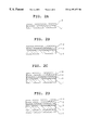
- FIGS. 2A-2D are schematic diagrams illustrating sectional views of typical recordable optical media
- FIGS. 3A-3C are schematic diagrams illustrating sectional views of typical optical recording media for CD-Rs.
- FIGS. 4A-4C are schematic diagrams illustrating sectional views of typical optical recording media for DVD-Rs.
- an optical recording medium which is useful for the next-generation high-capacity disc systems using a laser diode emitting light having a wavelength not greater than 700 nm, can be provided by forming a recording layer mainly including a dye having a specific structure.
- a recording layer mainly including a dye having a specific structure.
- an optical recording medium can be obtained, which can be used for the current CD-R systems and in which information can be reproduced by DVD-R systems because of having high reflectivity against light having a wavelength not greater than 700 nm.
- dyes having the following formula (2) or (3) are preferably used.
- R15 represents a phenyl group which may be substituted
- R17 and R18 independently represent a hydrogen atom, an alkyl group having 1 to 6 carbon atoms which may be substituted, or a phenyl group which may be substituted, wherein R17 and R18 may combine to form a ring
- X3 represents OR19 or NR20R21, wherein R19, R20 and R21 independently represent an alkyl group having 1 to 6 carbon atoms which may be substituted, or a phenyl group which may be substituted
- R16 represents COR22 or SO 2 R23, wherein R22 and R23 independently represent an alkyl group which may be substituted, or an aryl group which may be substituted.
- R24 represent an alkyl group which may be substituted, or a phenyl group which may be substituted
- R25 and R26 independently represent a hydrogen atom, an alkyl group which may be substituted, or an aryl group which may be substituted, wherein R25 and R26 may combine to form a ring
- Z1 represents COR27 or SO 2 R28, wherein R27 and R28 independently represent an alkyl group which may be substituted, or an aryl group which may be substituted.
- alkyl groups include primary alkyl groups such as amethyl group, an ethyl group, a n-propyl group, a n-butyl group, a n-pentyl group, a n-hexyl group, a n-heptyl group, a n-octyl group, a n-nonyl group, and a n-decyl group; secondary alkyl groups such as an isobutyl group, an isoamyl group, a 2-methylbutyl group, a 2-methylpentyl group, a 3-methylpentyl group, a 4-methylpentyl group, a 2-ethylbutyl group, a 2-methylhexyl group, a 3-methylhexyl group, a 4-methylhexyl group, a 5-methylhexyl group, a 2-ethylpentyl group, a
- these primary and secondary alkyl groups may be substituted with a group such as a hydroxy group, a halogen atom, a nitro group, a carboxyl group, a cyano group, an aryl group, a substituted aryl group, a heterocyclic ring group, and a substituted heterocyclic ring group. Further, these primary and secondary alkyl groups may be substituted with one of the alkyl groups mentioned above with an atom such as oxygen, sulfur and nitrogen therebetween.
- alkyl groups with an oxygen atom include a methoxymethyl group, a methoxyethyl group, an ethoxymethyl group, an ethoxyethyl group, a butoxyethyl group, an ethoxyethoxyethyl group, a phenoxyethyl group, a methoxypropyl group, an ethoxypropyl group, a piperidino group, and a morpholino group.
- alkyl groups with a sulfur atom include a methylthioethyl group, an ethylthioethyl group, an ethylthiopropyl group, and a phenylthioethyl group.
- alkyl groups with a nitrogen atom include a dimethylaminoethyl group, a diethylaminoethyl group, and a diethylaminopropyl group.
- aryl groups include a phenyl group, a naphthyl group, an anthranil group, a fluorenyl group, a phenalenyl group, a phenanthranil group, a triphenylenyl group, and a pyrenyl group.
- these aryl groups may be substituted with a hydroxy group, a halogen atom, a nitro group, a carboxyl group, a cyano group, an aryl group, a substituted aryl group, a heterocyclic ring group, and a substituted heterocyclic ring group.
- These aryl groups may be substituted with one of the alkyl groups mentioned above with an atom such as oxygen, sulfur and nitrogen therebetween.
- heterocyclic ring groups include a furyl group, a thienyl group, a pyrrolyl group, a benzofuryl group, an isobenzofuryl group, a benzothienyl group, an indolenyl group, an isoindolenyl group, a carbazolyl group, a pyridyl group, a piperidyl group, a quinolyl group, an isoquinolyl group, an oxazolyl group, an isooxazolyl group, a thiazolyl group, an isothiazolyl group, an imidazolyl group, a pyrazolyl group, a benzoimidazolyl group, a pyrazinyl group, a pyrimidyl group, a pyridazyl group, and a quinoxalinyl group.
- these aryl groups may be substituted with a hydroxy group, a halogen atom, a nitro group, a carboxy group, a cyano group, an aryl group, a substituted aryl group, a heterocyclic ring group, and a substituted heterocyclic ring group. Further, these aryl groups may be substituted with one of the alkyl groups mentioned above with an atom such as oxygen, sulfur and nitrogen therebetween.
- halogen atom examples include fluorine, chlorine, bromine and iodine.
- alkoxy groups include groups in which an alkyl group or a substituted alkyl group is directly connected with an oxygen atom.
- alkyl groups and substituted alkyl groups include the alkyl groups mentioned above.
- alkyloxy groups include groups in which an alkyl group or a substituted alkyl group is directly connected with an oxygen atom.
- alkyl groups and substituted alkyl groups include the alkyl groups mentioned above.
- aryloxy groups include groups in which an aryl group or a substituted aryl group is directly connected with an oxygen atom.
- aryl groups and substituted aryl groups include the aryl groups mentioned above.
- carbamoyl groups include groups in which a hydrogen atom, an alkyl group, a substituted alkyl group, an aryl group, or a substituted aryl group is independently and directly connected with the nitrogen atom of a carbamoyl group (>NCO—).
- alkyl groups, substituted alkyl groups, aryl groups and substituted aryl groups include the alkyl and aryl groups mentioned above.
- alkoxycarbonyl groups include groups in which an alkyl group or a substituted alkyl group is directly connected with the oxygen atom of an oxycarbonyl group (—OCO—).
- alkyl groups and substituted alkyl groups include the alkyl groups mentioned above.
- acyl groups include groups in which an alkyl group or a substituted alkyl group, an aryl group or a substituted aryl group is directly connected with the carbonyl carbon atom of an acyl group (—CO—).
- alkyl groups, substituted alkyl groups, aryl groups and substituted aryl groups include the alkyl groups and aryl groups mentioned above.
- alkylamino groups include groups in which an alkyl group or a substituted alkyl group is independently and directly connected with the nitrogen atom of an amino group (>N—).
- alkyl groups and substituted alkyl groups include the alkyl and aryl groups mentioned above.
- the alkyl groups may combine to form a group having a ring such as a piperidino group, a morpholino group, a pyrrolidyl group, a piperazinyl group, an indolenyl group and isoindolenyl group.
- arylamino groups include groups in which an aryl group or a substituted aryl group is directly connected with the nitrogen atom of an amino group (>N—).
- aryl groups and substituted aryl groups include the aryl groups mentioned above.
- amino groups include groups in which an alkyl group, a substituted alkyl group, an aryl group or a substituted aryl group is directly connected with the nitrogen atom of an amino group (>N—).
- alkyl group, substituted alkyl groups, aryl groups and substituted aryl groups include the alkyl groups and aryl groups mentioned above.
- alkyloxycarbonyl groups include groups in which an alkyl group or a substituted alkyl group is directly connected with the oxygen atom of an oxycarbonyl group (—OCO—).
- alkyl groups and substituted alkyl groups include the alkyl groups mentioned above.
- aryloxycarbonyl groups include groups in which an aryl group or a substituted aryl group is directly connected with the oxygen atom of an oxycarbonyl group (—OCO—).
- aryl groups and substituted aryl groups include the aryl groups mentioned above.
- alkylcarbonylamino groups include groups in which an alkyl group or a substituted alkyl group is directly connected with the carbon atom of a carbonylamino group (—CONH—).
- alkyl groups and substituted alkyl groups include the alkyl groups mentioned above.
- arylcarbonylamino groups include groups in which an aryl group or a substituted aryl group is directly connected with the carbon atom of a carbonylamino group (—CONH—).
- aryl groups and substituted aryl groups include the aryl groups mentioned above.
- alkylcarbamoyl groups include groups in which an alkyl group or a substituted alkyl group is directly connected with the nitrogen atom of a carbamoyl group (>NCO—).
- alkyl groups and substituted alkyl groups include the alkyl groups mentioned above.
- the alkyl groups may combine to form a group having a ring such as a piperidino group, a morpholino group, a pyrrolidyl group, a piperazinyl group, an indolenyl group and isoindolenyl group.
- arylcarbamoyl groups include groups in which an aryl group or a substituted aryl group is directly connected with the nitrogen atom of an carbamoyl group (>NCO—).
- aryl groups and substituted aryl groups include the aryl groups mentioned above.
- heterocyclic ring groups include an indolyl group, a furyl group, a thienyl group, a pyridyl group, a piperidyl group, a quinolyl group, an isoquinolyl group, a piperidino group, a morpholino group, and a pyrrolyl group.
- ringed amino groups which are formed by a combination of R4 with R5 include a piperidino group, a morpholino group, a pyrrolidyl group, a piperazyl group, an imidazolidyl group, a pyrazolidyl group, an indolinyl group, an isoindolinyl group, a pyrrolyl group, an indolyl group, an isoindolyl group, and a carbazolyl group.
- substituents having active hydrogen include a hydroxy group, a carboxy group, an amino group, an alkylcarbonylamino group, an arylcarbonylamino group, an alkylsulfonylamino group, an arylsulfonylamino group, a carbamoyl group, an alkylcarbamoyl group, an arylcarbamoyl group, a sulfo group, a sulfino group, a sulfeno group, and an aminosulfonyl group.
- alkylcarbonylamino group, arylcarbonylamino group, alkylcarbamoyl group and arylcarbamoyl group are mentioned above.
- alkylsulfonylamino group examples include groups in which an alkyl group or a substituted alkyl group is directly connected with the sulfur atom of a sulfonylamino group (—SO 2 NH—).
- alkyl groups and substituted alkyl group include the alkyl groups mentioned above.
- arylsulfonylamino group examples include groups in which an aryl group or a substituted aryl group is directly connected with the sulfur atom of a sulfonylamino group (—SO 2 NH—).
- aryl groups and substituted aryl groups include the aryl groups mentioned above.
- metal atoms for use in the azo chelate compounds of the present invention include aluminum, titanium, vanadium, chromium, manganese, iron, cobalt, nickel, copper, zinc, zirconium, niobium, molybdenum, technetium, ruthenium, rhodium, palladiumandthe like.
- Inparticular, azo chelate compounds including chromium, manganese, cobalt, nickel or copper have good optical properties and therefore are suitable as an optical recording material.
- the azo chelate compound of the present invention can be synthesized by, for example, a method described in detail by Inoue in Chem. Lett., 1981, pp 1733-1736. This method is as follows, however, the manufacturing method is not limited thereto.
- azo compounds having formula (1) can be synthesized.
- a nickel chelate compound By reacting the synthesized azo compound with, for example, nickel acetate in ethanol aqueous solution, a nickel chelate compound can be prepared.
- an azo chelate compound of the present invention can be manufactured.
- an intermediate of the azo chelate compound of the present invention 2-chloro-1,3,5-triazine having the following formula (8) whose 4 and 6 positions are substituted, such as the compound having formula (4), can be easily prepared by reacting cyanuric chloride with a compound which can perform a substitution reaction with a chlorine group.
- R27 and R28 of the compound having formula (8) are preferably SR7 or SR9.
- the resultant recording material has good optical properties such that the refractive index n of the resultant recording layer is from 1.5 to 3.0 when measured with light having a wavelength within ⁇ 5 nm of the wavelength of light for recording and reproducing, the extinction coefficient k of the recording layer is from 0.02 to 0.2 and the recording layer causes optical changes by irradiation with laser light having a wavelength of from 630 nm to 690 nm.
- R27 and R28 of the compound having formula (8) it is difficult to obtain an optical recording medium having good optical properties.
- Azo chelate compounds which are constituted of a metal and an azo dye having formula (1) including group having a sulfur atom, cause large changes in their optical properties when exposed to laser light having a wavelength of from 600 nm to 700 nm. Therefore, these azo chelate compounds are an ideal material for optical recording media.
- similar azo chelate compounds constituted of an azo dye having formula (1) including a group having an atom other than a sulfur atom have a little optical changes, and therefore it is difficult to use these compounds for optical recording media.
- the optical recording medium of the present invention is needed to have a large absorption band over a relatively short wavelength region in a wavelength range of from 630 nm to 690 nm of the wavelength range of the recording and reproducing laser light.
- the laser light used for recording and reproducing information preferably has a wavelength near the upper end of the wavelength range of from 630 nm to 690 nm (i.e., in the wavelength of the reading and reproducing laser light). This means that this optical recording medium has large refractive index and extinction coefficient in the wavelength range of form 630 nm to 690 nm.
- the recording layer of the optical recording medium of the present invention preferably has a refractive index n of from 1.5 to 3.0 and an extinction coefficient k of from 0.02 to 0.2 when the refractive index of only the recording layer is measured with light having a wavelength within ⁇ 5 nm of the wavelength of light used for recording and reproducing. It is not preferable for the recording layer to have a refractive index n not greater than 1.5, because only poor optical changes are obtained, and thereby the modulation factor in recording decreases.
- the recording layer it is also not preferable for the recording layer to have a refractive index n not less than 3.0, because the dependency of recording and reproducing on the wavelength of the light used for recording and reproducing is excessively enhanced, and thereby a problem such as mis-recording or mis-reproducing tends to occur even when light having a wavelength in the recording and reproducing wavelength range (630 to 690 nm) is used. It is not preferable for the recording layer to have an extinction coefficient k not greater than 0.02, because the recording sensitivity deteriorates. In addition, it is not preferable for the recording layer to have an extinction coefficient k not less than 0.2, because reflectivity of 50% or greater cannot be obtained.
- the thermal property requisite for the recording layer is that the weight of the recording layer rapidly decreases, as temperature increases, during a main weight decreasing process in thermogravimetry.
- the organic material layer decomposes during the main weight decreasing process, and thereby the thickness of the layer decreases and the optical constants thereof change, resulting in formation of optically-recorded portions.
- the weight loss is moderate during the main weight decreasing process, the recorded portions are formed during a wide temperature range, and therefore it is difficult to perform high-density recording.
- a material having a plurality of main weight decreasing processes is used as the recording layer, it is also difficult to perform high-density recording.
- the weight decreasing process having a maximum weight decreasing rate among weight decreasing processes is referred to as the main weight decreasing process.
- the slope of a weight decreasing curve as shown in FIG. 1 is determined by the following method.
- a sample organic material having a mass of M0 is heated at a heating speed of 10° C./min in a nitrogen atmosphere.
- the mass gradually decreases along an almost straight line a-b as shown in FIG. 1 .
- the temperature of the material reaches a certain temperature, the mass of the material rapidly decreases along an almost straight line c-d (this is the main weight decreasing process).
- the rapid decrease of mass i.e., the main weight decreasing process
- the weight-decrease starting point is T1
- the weight-decrease ending point is T2
- the slope of the weight decreasing curve is (m1 ⁇ m2) (%)/(T2 ⁇ T1) (° C.)
- the weight decreasing rate against the initial weight is (m1 ⁇ m2) (%).
- a material which has a slope of the weight decreasing curve not less than 2%/° C. during the main weight decreasing process, is used for the optical information recording medium, because an optical information recording medium having sharp record portions can be obtained, namely a high-density optical recording medium can be obtained.
- the weight decreasing rate during the main weight decreasing process is preferably not less than 30% to obtain an optical information recording medium having a good modulation factor in recording and good record sensitivity.
- the weight-decrease starting temperature is preferably not greater than 350° C., and more preferably from 250 to 350° C., to obtain an optical information recording medium in which recording can be stably performed without causing deterioration of reproduction and increasing the recording energy of laser light used.
- the optical recording medium of the present invention may have one of the structures of the typical recordable optical discs as shown in FIGS. 2A-2D, a so-called “air-sandwich” structure in which any two of ordinal recordable optical disc are adhered to each other with air therebetween, or a laminate structure in which any two of the typical recordable optical discs are adhered to each other without air therebetween.
- the optical recording medium of the present invention may have a structure such as the structures of typical CD-R media as shown in FIGS. 3A-3C or a structure such as the structures of typical DVD-R media as shown in FIGS. 4A-4C.
- numerals 1 , 2 , 3 , 4 and 5 denote asubstrate, a recording layer, an undercoat layer, a protective layer and a hard coat layer, respectively.
- numeral 6 denotes a light reflective metal layer.
- numerals 7 and 8 denote a second substrate and an adhesive layer, respectively.
- the optical recording medium of the present invention basically has a structure in which the recording layer 6 is formed on the substrate 1 .
- the recording layer 2 may be a single layer including an organic dye (hereinafter sometimes referred to as an organic dye layer) or a multi-layer in which an organic dye layer and a light reflective metal layer 6 are overlaid to increase reflectivity.
- the recording layer 2 is formed overlying the substrate 1 with the undercoat layer 3 and/or the protective layer 4 therebetween.
- the typical structure of the optical recording medium of the present invention is a multi-layer structure in which the organic dye layer, the metal reflection layer 6 , the protective layer 4 , the adhesive layer 8 and the second substrate 7 are overlaid on the substrate 1 one by one.
- guide grooves or guide pits of from 1000 to 2500 ⁇ in depth are formed for tracking, and pre-formats such as address signals are formed.
- the track pit is generally has a size of from 0.7 to 1.0 ⁇ m, however, the pitch is preferably from 0.7 to 0.8 ⁇ m for high-density data storage.
- the width of the grooves is preferably from 0.18 to 0.36 ⁇ m in half width to obtain satisfactory signal strength for tracking errors and to avoid the horizontal spread of recorded portions.
- the property requisite for the substrate 1 is to be transparent against laser light used if the recording and reproducing operations are performed from the side of the substrate 1 .
- the substrate is not necessarily transparent. In the present invention, when only one substrate is used, the substrate should be transparent. When two substrates are used and the second substrate is transparent, the substrate 1 may be transparent or untransparent.
- the material for use as the substrates 1 and 7 include plastics such as polyester resins, acrylic resins, polyamide resins, polycarbonate resins, polyolefin resins, phenolic resins, epoxy resins, and polyimide resins; glass, ceramics, and metals.
- plastics such as polyester resins, acrylic resins, polyamide resins, polycarbonate resins, polyolefin resins, phenolic resins, epoxy resins, and polyimide resins; glass, ceramics, and metals.
- each of layers, other than the recording layer 2 , light reflective metal layer 6 and protective layer 7 , such as the undercoat layer 3 and adhesive layer 8 formed overlying the substrate 1 is referred to as an intermediate layer.
- the intermediate layer is formed:
- high molecular weight materials such as ionomer resins, polyamide resins, vinyl resins, natural resins, natural high molecular weight materials, silicones, and liquid rubbers; silane coupling agents and the like are preferably used.
- inorganic compounds such as SiO 2 , MgF 2 , SiO, TiO 2 , ZnO, TiN, SiN and the like; metals or semi-metals such as Zn, Cu, Ni, Cr, Ge, Se, Au, Ag, Al and the like are preferably used as well as the high molecular weight materials mentioned above.
- metals such as Al, Ag, and the like; and a thin film of organic materials, which has metallic gloss, such as methine dyes, xanthene dyes and the like can be used.
- ultraviolet crosslinking resins, thermosetting resins, thermoplastic resins and the like can be used.
- the thickness of the intermediate layer is preferably from 0.01 to 30 ⁇ m, and more preferably from 0.05 to 10 ⁇ m.
- Information can be recorded in the recording layer by changing the optical properties of the recording layer 2 with laser light. It is needed for the recording layer 2 to include the dye of the present invention.
- the dye of the present invention can be used alone or in combination in the recording layer 2 .
- other organic dyes, metals or metal compounds can also be used while being mixed with the dye of the present invention or while being included in a layer which is overlaid on the recording layer 2 .
- organic dyes for use in the recording layer 2 include polymethine dyes, naphthalocyanine dyes, phthalocyanine dyes, squarylium dyes, croconium dyes, pyrylium dyes, naphthoquinone dyes, anthraquinone (Indanthrene) dyes, xanthene dyes, triphenyl methane dyes, azulene dyes, tetrahydrocholine dyes, phenanthrene dyes, triphenothiazine dyes, and metal chelate compounds. These dyes are used alone or in combination.
- the dye of the present invention When the dye of the present invention is used in combination with dyes having maximum absorption in a wavelength range of from 680 to 750 nm to prepare a CD-R medium which can record and reproduce information with light having a relatively short wavelength, known dyes disclosed in Japanese Patent Publications mentioned above in the paragraph of discussion of the related art in the present application can be used. Specific examples of the dyes which have maximum absorption in a wavelength range of from 680 to 750 nm include the following dyes:
- R1, R2, R3 and R4 independently represent an alkyl group having 1 to 3 carbon atoms; R5 and R6 independently represent an alkyl group having 1 to 6 carbon atoms which may be substituted; X represents an acid anion; and the aromatic rings may be condensed with another aromatic ring and may be substituted with a halogen atom, an alkyl group, an alkoxy group or an acyl group.
- M1 represents Ni, Pd, Cu, Zn, Co, Mn, Fe, TiO or VO
- X1 to X4 independently represent a group of —OR or —SR which connects the ⁇ -position thereof, or a hydrogen atom except that X1 to X4 are all a hydrogen atom, wherein the substituents of the benzene rings other than the groups X1 to X4 are a hydrogen or a halogen atom, and wherein R represents an alkyl group having 3 to 12 carbon atoms which may be substituted and may be linear or branched, a cycloalkyl group, or an aryl group which may be substituted.
- M2 represents Si, In or Sn
- X5 to X8 independently represent a group of —OR or —SR which connects the ⁇ -position thereof, or a hydrogen atom except that X5 to X8 are all a hydrogen atom, wherein the substituents of the benzene rings other than the groups X5 to X8 are a hydrogen or a halogen atom and wherein R is defined above in formula (10); and Y1 and Y2 independently represent a group of —OSiRaRbRc, —OCORa, or —OPORaRb, wherein Ra, Rb and Rc independently represent an alkyl group having 1 to 10 carbon atoms, or an aryl group.
- the compounds having formula (12) are a compound constituted of one or more of the azo chelate compounds in which the metal is preferably Ni, Pt, Pd, Co, Cu, Zn and the like;
- A represents a residual group which forms a heterocyclic ring together with the carbon atom and the nitrogen atom with which A combines;
- B represents a residual group which forms an aromatic ring or a heterocyclic ring together with the carbon atoms with which B combines; and
- X represents a group having active hydrogen.
- the mixing ratio of the dye of the present invention to the above-mentioned dye having maximum absorption in a wavelength range of from 680 to 750 nm is preferably from 10:100 to 90:100, and more preferably from 20:100 to 40:100.
- the thickness of the recording layer 2 is preferably from 500 ⁇ to 5 ⁇ m, and more preferably from 1000 ⁇ to 5000 ⁇ .
- one or more metals or metal compounds such as In, Te, Bi, Se, Sb, Ge, Sn, Al, Be, TeO 2 , SnO, As, Cd and the like can be mixed with the dyes mentioned above while being dispersed therein.
- a layer of the above-mentioned metal or metal compound may be formed adjacent to the dye layer.
- the dye layer may include a material such as high molecular weight materials, e.g., ionomer resins, polyamide resins, vinyl resins, natural high molecular weight materials, silicones and liquid rubbers; and silane coupling agents.
- a stabilizer such as complexes of transition metals, dispersants, flame retardants, lubricants, antistatic agents, surfactants, plasticizers and the like can be used in combination with the dyes mentioned above to improve various properties.
- the recording layer 2 can be formed by a known method such as vacuum evaporation methods, sputtering methods, chemical vapor deposition (CVD) methods, and coating methods.
- a coating liquid which is prepared by dissolving the above-mentioned dye in an appropriate organic solvent, is coated by a known coating method such as spray coating methods, roller coating methods, dip coating methods, and spin coating methods.
- organic solvents for use in the coating liquid include alcohols such as methanol, ethanol, and isopropanol; ketones such as acetone, methyl ethyl ketone and cyclohexanone; amides such as N,N-dimethylformamide and N,N-dimethylacetoamide; sulfoxides such as dimethylsulfoxides; ethers such as tetrahydrofuran, dioxane, diethylether and ethylene glycol monomethyl ether; esters such as methyl acetate and ethyl acetate; halogenated aliphatic hydrocarbons such as chloroform, methylene chloride, dichloroethane, carbon tetrachloride and trichloroethane; aromatic hydrocarbons such as benzene, xylene, monochlorobenzene and dichlorobenzene; cellosolves such as methoxyethanol and ethoxyethanol; hydrocarbons such
- the thickness of the recording layer 2 is preferably from 100 ⁇ to 10 ⁇ m, and preferably from 200 ⁇ to 2000 ⁇ .
- Suitable metals for use in the light reflective metal layer 6 include metals and semi-metals which have a high reflectivity themselves and which are hardly corroded.
- Specific examples of such metals and semi-metals include Au, Ag, Cr, Ni, Al, Fe, Sn and the like.
- Au, Ag and Al is most preferable because of having good reflectivity and productivity.
- These metals and semi-metals can be used alone or in combination.
- the light reflective metal layer 6 can be formed by a method such as vacuum evaporation methods, sputtering methods and the like.
- the thickness thereof is preferably from 50 to 5000 ⁇ , and more preferably from 100 to 3000 ⁇ .
- the protective layer 4 and the hard coat layer 5 are formed:
- thermosoftenable or thermofusible resins e.g., polymethyl methacrylate, polycarbonate, epoxy resins, polystyrene resins, polyester resins, vinyl resins, cellulose resins, aliphatic hydrocarbon resins, aromatic hydrocarbon resins, natural rubbers, styrene-butadiene resins, chloroprene rubbers, waxes, alkyd resins, drying oils and rosins can also be used.
- ultraviolet crosslinking resins are most preferable for the protective layer 4 and the hard coat layer 5 because of having good productivity.
- the thickness of the protective layer 4 and the hard coat layer 5 is preferably form 0.01 to 30 ⁇ m, and more preferably from 0.05 to 10 ⁇ m.
- stabilizers, dispersants, flame retardants, lubricants, antistatic agents, surfactants, plasticizers and the like can also be included in the intermediate layer, protective layer 4 and hard coat layer 5 .
- optical recording medium including one or more of the azo chelate compounds of the present invention
- light having a wavelength of from 630 to 690 nm is preferably used for reproducing information.
- light having a wavelength of from 770 to 810 nm is preferably used for recording information, and light has a wavelength of from 770 to 810 nm or from 630 to 690 nm is preferably used for reproducing information.
- Metal chelate compounds including an azo compound having the following formula (13) are examples of the azo chelate compounds of the present invention.
- An organic dye layer including a compound No. 6 was formed on a polycarbonate substrate of 0.6 mm in thickness which had been prepared by injection molding and which had guide grooves having a depth of 1400 ⁇ , a half width of 0.35 ⁇ m, and a track pitch of 1.0 ⁇ m.
- the organic dye layer was formed by coating by a spin coating method a coating liquid in which compound No. 6 was dissolved in a mixed solvent of methylcyclohexane, 2-methoxyethanol and methyl ethyl ketone.
- the thickness of the dye layer was 800 ⁇ .
- a light reflective gold layer having a thickness of 2000 ⁇ was formed thereon by a sputtering method, and further thereon a protective layer having a thickness of 5 ⁇ m was formed by coating an acrylic photopolymer.
- optical recording medium of the present invention was prepared.
- Example 1 The procedure for preparation of the optical recording medium in Example 1 was repeated except that compound No. 6 was replaced with a compound No. 7, 13, 21, 23 or 25.
- optical recording media of the present invention were prepared.
- optical recording media of Examples 1 to 6 and Comparative Example 1 was evaluated with respect to the following items:
- Absolute reflectivity was measured by a V-N method using a spectrophotometer. The unit of absolute reflectivity is percent (%).
- a C/N ratio was evaluated by the following recording and reproducing:
- Wavelength of oscillated laser 635 nm (NA of 0.6)
- Wavelength of oscillated laser 650 nm
- the unit of C/N ratio is dB.
- each optical recording medium was evaluated with respect to reflectivity and C/N ratio.
- an organic dye layer having a thickness of 1700 ⁇ was formed on the substrate.
- a light reflective gold layer having a thickness of 2000 ⁇ was formed thereon by a sputtering method, and further thereon a protective layer having a thickness of 5 ⁇ m was formed by coating an acrylic photo-polymer.
- optical recording medium of the present invention was prepared.
- Example 7 The procedure for preparation of the optical recording medium in Example 7 was repeated except that compound No. 11 was replaced with a compound No. 10 or 23.
- optical recording media of the present invention were prepared.
- optical recording media of the present invention were prepared.
- Example 7 The procedure for preparation of the optical recording medium in Example 7 was repeated except that the mixture of the compound having formula (14) with a compound No.11 was replaced with the compound having formula (14).
- Example 7 The procedure for preparation of the optical recording medium in Example 7 was repeated except that the mixture of the compound having formula (14) with a compound No.11 was replaced with the compound having formula (15).
- optical recording media of Examples 7 to 11 and Comparative Examples 2 and 3 was evaluated with respect to the following items:
- EFM signals were recorded at a linear speed of 1.4 m/sec using laser light of a laser diode having a wavelength of 780 nm and a beam diameter of 1.6 ⁇ m while tracking.
- the signals were reproduced with the laser light used for recording, or continuous light of a laser diode having a wavelength of 650 nm and a beam diameter of 1. 0 ⁇ m.
- the waveform of the reproduced signals was observed.
- Azo chelate compounds including an azo compound having the following formula (16) are examples of the azo chelate compounds of the present invention.
- an organic dye layer having a thickness of 800 ⁇ was formed on the substrate.
- a light reflective gold layer having a thickness of 1500 ⁇ was formed thereon by a sputtering method, and further thereon a protective layer having a thickness of 5 ⁇ m was formed by coating an acrylic photo-polymer.
- a polycarbonate substrate prepared by injection molding and having a thickness of 0.6 mm was laminated thereon.
- optical recording medium of the present invention was prepared.
- Example 12 The procedure for preparation of the optical recording medium in Example 12 was repeated except that compound No. 32 was replaced with a compound No. 33, 37, 38, 43, 47, 54 or 67.
- optical recording media of the present invention were prepared.
- Example 12 The procedure for preparation of the optical recording medium in Example 12 was repeated except that compound No. 32 was replaced with a compound having the following formula (17), (18) or (19).
- optical recording media of Examples 12 to 19 and Comparative Examples 4 to 6 was evaluated with respect to reflectivity.
- the conditions were as follows:
- Wavelength of oscillated laser 635 nm
- Wavelength of oscillated laser 650 nm
- each optical recording medium was evaluated with respect to light-deterioration rate constant.
- Guide grooves having a depth of 1600 ⁇ , a half width of 0.24 ⁇ m, and a track pitch of 0.74 ⁇ m were formed using a photo-polymer on a polycarbonate resin substrate prepared by injection molding.
- a liquid in which a compound No. 76 was dissolved in a mixed solvent of methylcyclohexane, 2-methoxyethanol and methyl ethyl ketone was coated on the substrate by a spin coating method to form an organic dye layer having a thickness of 800 ⁇ .
- a light reflective gold layer having a thickness of 2000 ⁇ was formed thereon by a sputtering method. Further thereon a protective layer having a thickness of 5 ⁇ m was formed by coating an acrylic photo-polymer.
- optical recording medium of the present invention was prepared.
- Example 20 The procedure for preparation of the optical recording medium in Example 20 was repeated except that compound No. 76 was replaced with each of compounds Nos. 77-87 and 93-95.
- optical recording media of the present invention were prepared.
- Each of the optical recording media of Examples 20 to 34 was evaluated with respect to reflectivity and modulation factor.
- reflectivity and modulation factor were also measured after a light irradiation test or a preservation test.
- EFM signals were recorded at a linear speed of 3.4 m/sec using laser light of a laser diode having a wavelength of 650 nm and a beam diameter of 1.0 ⁇ m while tracking.
- the signals were reproduced with continuous light of a laser diode having a wavelength of 650 nm, a beam diameter of 1.0 ⁇ m and a reproduction power of 0.7 mW. The waveform of the reproduced signals was observed.
- Each optical recording medium was preserved for 500 hours under conditions of 85° C. in temperature and 85% in relative humidity.
- an organic dye layer having a thickness of 1700 ⁇ was formed on the substrate.
- a light reflective gold layer having a thickness of 2000 ⁇ was formed thereon by a sputtering method, and further thereon a protective layer having a thickness of 5 ⁇ m was formed by coating an acrylic photo-polymer.
- optical recording medium of the present invention was prepared.
- Example 35 The procedure for preparation of the optical recording medium in Example 35 was repeated except that compound No. 88 was replaced with a compound No. 89 or 90.
- optical recording media of the present invention were prepared.
- Example 35 The procedure for preparation of the optical recording medium in Example 35 was repeated except that compound No. 88 was replaced with a compound No. 91 or 92 while the compound having formula (14) was replaced with the compound having formula (15).
- optical recording media of the present invention were prepared.
- Each of the optical recording media of Examples 35-39 was evaluated with respect to reflectivity and C/N ratio. In addition, reflectivity and C/N ratio were also measured after a light irradiation test or a preservation test.
- EFM signals were recorded at a linear speed of 1.4 m/sec using laser light of a laser diode having a wavelength of 780 nm and a beam diameter of 1.6 ⁇ m while tracking.
- the signals were reproduced with the laser light used for recording, or continuous light of a laser diode having a wavelength of 650 nm, and a beam diameter of 1.0 ⁇ m.
- the waveform of the reproduced signals was observed.
- a methyl cellosolve solution of a compound No. 76 was coated by a spin coating method on a polycarbonate substrate of 0.6 mm in thickness which had been prepared by injection molding and in which guide grooves having a depth of 1600 ⁇ , a half width of 0.35 ⁇ m and a track pitch of 1.0 ⁇ m had been formed by coating a photo-polymer.
- optical recording medium of the present invention was prepared.
- Example 40 The procedure for preparation of the optical recording medium in Example 40 was repeated except that compound No. 76 was replaced with each of compounds Nos. 77-81.
- optical recording media of the present invention were prepared.
- Example 40 The procedure for preparation of the optical recording medium in Example 40 was repeated except that compound No. 76 was replaced with the compound having formula (14).
- Each of the optical recording media of Examples 40 to 45 and Comparative Example 7 was evaluated with respect to reflectivity and C/N ratio.
- reflectivity and C/N ratio were also measured after a light irradiation test and a preservation test.
- the recording and reproducing conditions are as follows:
- Wavelength of oscillated laser 635 nm
- Wavelength of oscillated laser 650 nm
- Reproduction power 0.6 to 0.9 mW (continuous light)
- Each optical recording medium was preserved for 500 hours under conditions of 85° C. in temperature and 85% in relative humidity.
- an organic dye layer having a thickness of 800 ⁇ was formed on the substrate.
- a light reflective gold layer having a thickness of 1500 ⁇ was formed thereon by a sputtering method, and further thereon a protective layer having a thickness of 5 ⁇ m was formed by coating an acrylic photo-polymer.
- optical recording medium of the present invention was prepared.
- Example 46 The procedure for preparation of the optical recording medium in Example 46 was repeated except that compound No. 82 was replaced with a compound No. 83, 84, 85, 86 or 87.
- optical recording media of the present invention were prepared.
- Example 46 The procedure for preparation of the optical recording medium in Example 46 was repeated except that compound No. 82 was replaced with the compound having formula (14).
- Each of the optical recording media of Examples 46 to 51 and Comparative Example 8 was evaluated with respect to reflectivity and reproduced waveform.
- EFM signals were recorded at a linear speed of 3.0 m/sec using laser light having a wavelength of 635 nm and a beam diameter of 1.0 ⁇ m while tracking (the length of the shortest mark was 0.4 ⁇ m).
- the signals were reproduced with continuous light of a laser diode having a wavelength of 650 nm and a power of 0.7mW. The waveform of the reproduced signals was observed.
- an organic dye layer having a thickness of 1700 ⁇ was formed on the substrate.
- a light reflective gold layer having a thickness of 2000 ⁇ was formed thereon by a sputtering method, and further thereon a protective layer having a thickness of 5 ⁇ m was formed by coating an acrylic photo-polymer.
- optical recording medium of the present invention was prepared.
- Example 52 The procedure for preparation of the optical recording medium in Example 52 was repeated except that compound No. 88 was replaced with a compound No. 89 or 90.
- optical recording media of the present invention were prepared.
- Example 52 The procedure for preparation of the optical recording medium in Example 52 was repeated except that compound No. 88 was replaced with a compound No. 91 or 92 while the compound having formula (14) was replaced with the compound having formula (15).
- optical recording media of the present invention were prepared.
- EFM signals were recorded in each optical recording medium of Examples 52-56 and Comparative Examples 9-10 at a linear speed of 1.4 m/sec using laser light of a laser diode having a wavelength of 780 nm and a beam diameter of 1.6 ⁇ m while tracking.
- the signals were reproduced with continuous light of a laser diode having a wavelength of 650 nm and a beam diameter of 1.0 ⁇ m. The waveform of the reproduced signals was observed.
- the optical recording media of the present invention can record and reproduce information with laser light having a wavelength in a range of from 630 to 700 nm, and have good light resistance and good preservation stability.
- the optical recording medium can be used not only as a CD-R useful for the current systems, but also as a recording medium for the next-generation optical disc systems. Further the optical recording medium of the present invention can also be used as a DVD-R medium, and the information which has been recorded in the optical recording medium of the present invention using a current CD-R system can be reproduced with a high-density recording system.
Landscapes
- Physics & Mathematics (AREA)
- Optics & Photonics (AREA)
- Chemical & Material Sciences (AREA)
- Organic Chemistry (AREA)
- Optical Record Carriers And Manufacture Thereof (AREA)
- Thermal Transfer Or Thermal Recording In General (AREA)
- Optical Head (AREA)
Abstract
An optical recording material including a substrate and a recording layer which is formed overlying the substrate, wherein the recording layer includes an azo chelate compound including an azo compound and at least one of a metal and a metal salt, and wherein the azo compound has the following formula (1): 
Description
1. Field of the Invention
The present invention relates to a high-capacity optical recording medium for storing data, and more particularly to a recordable high-capacity optical disc such as recordable high-capacity compact discs and recordable digital video discs.
2. Discussion of the Related Art
Currently, DVD-Rs (digital video disc-recordable) have been developed as next-generation high-capacity optical discs. In order to increase the recording capacity of DVD-Rs, the following technologies are needed:
(1) recording materials in which relatively small recording pits can be formed;
(2) advanced image compression technologies such as MPEG2 (Motion Picture Experts Group); and
(3) a laser diode emitting light having a relatively short wavelength for reading relatively small pits.
As for the laser diodes emitting light in the red region, only AlGaInP laser diodes, which emit light having a wavelength of 670 nm, have been developed for commercial operation and used for bar code readers and measuring instruments. With the capacity of optical discs increased, red color laser diodes have been used in the optical data storage field. In a case of DVD drives, light within the 635 nm band or 650 nm band, which is emitted by laser diodes, is standardized as a light source. In order to perform high-density recording, it is desirable for the light used for high-density recording to have as short a wavelength as possible. Therefore, the light having a wavelength of 635 nm is preferably used for drives for recording information in recordable optical media. In contrast, as for the read-only DVD-ROM (digital video disc-read-only-memory) drives, drives using light having a wavelength of 650 nm are marketed.
Until now, the following write-once read-many-times information recording media (WORM) have been proposed:
(1) recording media using a cyanine dye as a recording material, which have been disclosed in Japanese Laid-Open Patent Publications Nos. 57-82093, 58-56892, 58-112790, 58-114989, 59-85791, 60-83236, 60-89842 and 61-25886;
(2) recording media using a phthalocyanine dye as a recording material, which have been disclosed in Japanese Laid-Open Patent Publications Nos. 61-150243, 61-177287, 61-154888, 61-24609, 62-39286, 63-37991 and 63-39888;
The following background art concerning recordable compact discs (CD-Rs) has been proposed:
(1) recording media using a cyanine dye and a light reflective metal layer as a recording material, which have been disclosed in Japanese Laid-Open Patent Publications Nos. 1-159842, 2-42652, 2-13656 and 2-168446;
(2) recording media using a phthalocyanine dye and a light reflective metal layer as a recording material, which have been disclosed in Japanese Laid-Open Patent Publications Nos. 1-176585, 3-215446, 4-113886, 4-226390, 5-1272, 5-171052, 5-116456, 5-96860 and 5-139044; and
(3) recording media using an azo chelate dye and a light reflective metal layer as a recording material, which have been disclosed in Japanese Laid-Open Patent Publications Nos. 4-46186, 4-141489, 4-361088, 5-279580, 7-51673, 7-161069, 7-37272, 7-71867, 8-231866, 8-295811, 9-277703, and 10-36693.
In addition, the following background art concerning recordable compact discs (CD-Rs), which can perform only reproduction in DVD system, has been proposed:
(1) recording media using a combination of a CD-R recording material with an azo dye capable of absorbing light having a relatively short wavelength as a recording material, which have been disclosed in Japanese Laid-Open Patent Publications Nos. 8-156408, 8-310121, 9-39394 and 9-40659;
(2) recording media using a combination of a CD-R recording material with an azaannulene dye capable of absorbing light having a relatively short wavelength as a recording material, which have been disclosed in Japanese Laid-Open Patent Publications Nos. 8-276662 and 8-287513; and
(3) recording media using a combination of a CD-R recording material with another dye capable of absorbing light having a relatively short wavelength as a recording material, which have been disclosed in Japanese Laid-Open Patent Publications Nos. 8-169182, 8-310129 and 8-324117.
Further, the following background art concerning recordable high-capacity compact discs (DVD-Rs) has been proposed:
(1) recording media using a cyanine dye and a light reflective metal layer as a recording material; and
(2) recording media using an imidazole type azomethine dye and a light reflective metal layer as a recording material, which have been disclosed in Japanese Laid-Open Patent Publications Nos. 8-198872, 8-209012 and 8-283263.
Under such circumstances, a medium, which can record and reproduce information with light having a wavelength of 635 nm and in addition can reproduce information with light having a wavelength of 650 nm, are most preferable as the DVD-R media. However, a DVD-R medium, which can record and reproduce information with an optical pickup using light having a wavelength not greater than 650 nm and which has good light resistance and good preservability, has not yet been developed.
The current CD-R disc systems are designed so that record and reproduction can be performed by laser light having a wavelength of from 770 nm to 790 nm. On the other hand, since CD-Rs use in the recording layer thereof a dye having maximum absorption in a wavelength range of from 680 nm to 750 nm and are designed so as to have high reflectivity against light in a wavelength range of from 770 nm to 790 nm by controlling their optical constants and layer thickness, CD-Rs have very poor reflectivity against light having a wavelength not greater than 700 nm. Therefore, a problem tends to occur in that information, which is recorded in a CD-R by the current CD-R systems and which can be reproduced by the CD-R systems, cannot be reproduced by DVD-R disc systems.
Because of these reasons, a need exists for an optical recording medium in which information can be recorded and reproduced by DVD-R disc systems and which has good light resistance and good preservability.
Accordingly, an object of the present invention is to provide an optical recording medium which has good light resistance and good preservability and which can be used in DVD-R disc systems using a laser diode emitting light having a relatively short wavelength.
Another object of the present invention is to provide an optical recording medium in which information recorded in the optical recording medium by CD-R disc systems can be reproduced by DVD-R disc systems.
To achieve such objects, the present invention contemplates the provision of an optical recording material which has a substrate and a recording layer which is formed overlying the substrate, wherein the recording layer includes an azo chelate compound including an azo compound and at least one of a metal and a metal salt and wherein the azo compound has the following formula (1): 
wherein R1-R3 independently represent a hydrogen atom, a halogen atom, a nitro group, a cyano group, a hydroxy group, a carboxyl group, an amino group, a carbamoyl group, an alkyl group which may be substituted, an aryl group which may be substituted, a heterocyclic group which may be substituted, an alkyloxy group which may be substituted, an aryloxy group which may be substituted, an alkylamino group which may be substituted, an arylamino group which may be substituted, an alkyloxycarbonyl group which may be substituted, an aryloxycarbonyl group which may be substituted, an alkylcarbonylamino group which may be substituted, an arylcarbonylamino group which may be substituted, an alkylcarbamoyl group which may be substituted, an arylcarbamoyl group which may be substituted, or an alkenyl group which may be substituted; R4 and R5 independently represent a hydrogen atom, an alkyl group which may be substituted, or aryl group which may be substituted, wherein R1 and R2, R2 and R4 or R5, R3 and R4 or R5, and R4 and R5 may combine to form a ring; X1 represents R6 or SR7, wherein R6 represents a hydrogen atom, a halogen atom, a nitro group, a cyano group, a hydroxy group, a carboxyl group, an alkyl group which may be substituted, a phenyl group which may be substituted, an alkoxy group which may be substituted, an aryloxy group which may be substituted, a carbamoyl group which may be substituted, an acyl group which may be substituted, an alkoxycarbonyl group which may be substituted, an aryloxycarbonyl group which may be substituted, an alkenyl group which may be substituted, or an amino group which may be substituted; and R7 represents a hydrogen atom, an alkyl group which may be substituted, or an aryl group which may be substituted; X2 represents R8, SR9, OR10 or NR11R12, wherein R8 represents the same groups as mentioned above for use as R6, R9 represents an alkyl group which may be substituted, and R10, R11 and R12 independently represent an alkyl group which may be substituted, or an aryl group which may be substituted; and Z represents a group having active hydrogen.
Preferably, Z is a group selected from the group consisting of a hydroxy group and its derivatives, a carboxyl group and its derivatives, an amino group and its derivatives, a sulfo group and its derivatives, an amide group NHX3 in which X3 represents COR13 in which R13 represents an alkyl group which may be substituted or an aryl group which may be substituted, and a sulfonamide group NHX4 in which X4 represents SO2R14 in which R13 represents an alkyl group which may be substituted or an aryl group which may be substituted.
In addition, the metal of the azo chelate compound is preferably a metal selected from the group consisting of manganese, chromium, iron, cobalt, nickel and copper.
These and other objects, features and advantages of the present invention will become apparent upon consideration of the following description of the preferred embodiments of the present invention taken in conjunction with the accompanying drawings.
FIG. 1 is a graph illustrating a weight changing curve of an organic compound when the organic compound is heated;
FIGS. 2A-2D are schematic diagrams illustrating sectional views of typical recordable optical media;
FIGS. 3A-3C are schematic diagrams illustrating sectional views of typical optical recording media for CD-Rs; and
FIGS. 4A-4C are schematic diagrams illustrating sectional views of typical optical recording media for DVD-Rs.
As a result of the present inventors' examination, an optical recording medium, which is useful for the next-generation high-capacity disc systems using a laser diode emitting light having a wavelength not greater than 700 nm, can be provided by forming a recording layer mainly including a dye having a specific structure. In addition, it is also discovered that by using a mixture of the specific dye with an organic dye which has been used for the current CD-Rs, an optical recording medium can be obtained, which can be used for the current CD-R systems and in which information can be reproduced by DVD-R systems because of having high reflectivity against light having a wavelength not greater than 700 nm.
In the optical recording medium of the present invention, dyes having the following formula (1) are used. 
Among these dyes, dyes having the following formula (2) or (3) are preferably used. 
wherein R15 represents a phenyl group which may be substituted; R17 and R18 independently represent a hydrogen atom, an alkyl group having 1 to 6 carbon atoms which may be substituted, or a phenyl group which may be substituted, wherein R17 and R18 may combine to form a ring; X3 represents OR19 or NR20R21, wherein R19, R20 and R21 independently represent an alkyl group having 1 to 6 carbon atoms which may be substituted, or a phenyl group which may be substituted; and R16 represents COR22 or SO2R23, wherein R22 and R23 independently represent an alkyl group which may be substituted, or an aryl group which may be substituted. 
wherein R24 represent an alkyl group which may be substituted, or a phenyl group which may be substituted; R25 and R26 independently represent a hydrogen atom, an alkyl group which may be substituted, or an aryl group which may be substituted, wherein R25 and R26 may combine to form a ring; and Z1 represents COR27 or SO2R28, wherein R27 and R28 independently represent an alkyl group which may be substituted, or an aryl group which may be substituted.
In formulae (1), (2) and (3), specific examples of the alkyl groups include primary alkyl groups such as amethyl group, an ethyl group, a n-propyl group, a n-butyl group, a n-pentyl group, a n-hexyl group, a n-heptyl group, a n-octyl group, a n-nonyl group, and a n-decyl group; secondary alkyl groups such as an isobutyl group, an isoamyl group, a 2-methylbutyl group, a 2-methylpentyl group, a 3-methylpentyl group, a 4-methylpentyl group, a 2-ethylbutyl group, a 2-methylhexyl group, a 3-methylhexyl group, a 4-methylhexyl group, a 5-methylhexyl group, a 2-ethylpentyl group, a 3-ethylpentyl group, a 2-methylheptyl group, a 3-methylheptyl group, a 4-methylheptyl group, a 5-methylheptyl group, a 2-ethylhexyl group, a 3-ethylhexyl group, an isopropyl group, a sec-butyl group, a 1-ethylpropyl group, a 1-methylbutyl group, a 1,2-dimethylpropyl group, a 1-methylheptyl group, a 1-ethylbutyl group, a 1,3-dimethylbutyl group, a 1,2-dimethylbutyl group, a 1-ethyl-2-methylpropyl group, a 1-methylhexyl group, a 1-ethylheptyl group, a 1-propylbutyl group, a 1-isopropyl-2-methylpropyl group, a 1-ethyl-2-methylbutyl group, a 1-propyl-2-methylpropyl group, a 1-ethylhexyl group, a 1-propylpentyl group, a 1-isopropylpentyl group, a 1-isopropyl-2-methylbutyl group, a 1-isopropyl-3-methylbutyl group, a 1-methyloctyl group, a 1-ethylheptyl group, a 1-propylhexyl group, and a 1-isobutyl-3-methylbutyl group; tertiary alkyl groups such as a neopentyl group, a tert-butyl group, a tert-hexyl group, a tert-amyl group, and a tert-octyl group; and cycloalkyl groups such as a cyclohexyl group, a 4-methylcyclohexyl group, a 4-ethylcyclohexyl group, a 4-tert-butylcyclohexyl group, a 4-(2-ethylhexyl)cyclohexyl group, a bornyl group, and an isobornyl group (i.e., an adamantane group).
In addition, these primary and secondary alkyl groups may be substituted with a group such as a hydroxy group, a halogen atom, a nitro group, a carboxyl group, a cyano group, an aryl group, a substituted aryl group, a heterocyclic ring group, and a substituted heterocyclic ring group. Further, these primary and secondary alkyl groups may be substituted with one of the alkyl groups mentioned above with an atom such as oxygen, sulfur and nitrogen therebetween. Specific examples of such alkyl groups with an oxygen atom include a methoxymethyl group, a methoxyethyl group, an ethoxymethyl group, an ethoxyethyl group, a butoxyethyl group, an ethoxyethoxyethyl group, a phenoxyethyl group, a methoxypropyl group, an ethoxypropyl group, a piperidino group, and a morpholino group. Specific examples of such alkyl groups with a sulfur atom include a methylthioethyl group, an ethylthioethyl group, an ethylthiopropyl group, and a phenylthioethyl group. Specific examples of such alkyl groups with a nitrogen atom include a dimethylaminoethyl group, a diethylaminoethyl group, and a diethylaminopropyl group.
Specific examples of the aryl groups include a phenyl group, a naphthyl group, an anthranil group, a fluorenyl group, a phenalenyl group, a phenanthranil group, a triphenylenyl group, and a pyrenyl group. In addition, these aryl groups may be substituted with a hydroxy group, a halogen atom, a nitro group, a carboxyl group, a cyano group, an aryl group, a substituted aryl group, a heterocyclic ring group, and a substituted heterocyclic ring group. These aryl groups may be substituted with one of the alkyl groups mentioned above with an atom such as oxygen, sulfur and nitrogen therebetween.
Specific examples of the heterocyclic ring groups include a furyl group, a thienyl group, a pyrrolyl group, a benzofuryl group, an isobenzofuryl group, a benzothienyl group, an indolenyl group, an isoindolenyl group, a carbazolyl group, a pyridyl group, a piperidyl group, a quinolyl group, an isoquinolyl group, an oxazolyl group, an isooxazolyl group, a thiazolyl group, an isothiazolyl group, an imidazolyl group, a pyrazolyl group, a benzoimidazolyl group, a pyrazinyl group, a pyrimidyl group, a pyridazyl group, and a quinoxalinyl group. In addition, these aryl groups may be substituted with a hydroxy group, a halogen atom, a nitro group, a carboxy group, a cyano group, an aryl group, a substituted aryl group, a heterocyclic ring group, and a substituted heterocyclic ring group. Further, these aryl groups may be substituted with one of the alkyl groups mentioned above with an atom such as oxygen, sulfur and nitrogen therebetween.
Specific examples of the halogen atom include fluorine, chlorine, bromine and iodine.
Specific examples of the alkoxy groups include groups in which an alkyl group or a substituted alkyl group is directly connected with an oxygen atom. Specific examples of the alkyl groups and substituted alkyl groups include the alkyl groups mentioned above.
Specific examples of the alkyloxy groups include groups in which an alkyl group or a substituted alkyl group is directly connected with an oxygen atom. Specific examples of the alkyl groups and substituted alkyl groups include the alkyl groups mentioned above.
Specific examples of the aryloxy groups include groups in which an aryl group or a substituted aryl group is directly connected with an oxygen atom. Specific examples of the aryl groups and substituted aryl groups include the aryl groups mentioned above.
Specific examples of the carbamoyl groups include groups in which a hydrogen atom, an alkyl group, a substituted alkyl group, an aryl group, or a substituted aryl group is independently and directly connected with the nitrogen atom of a carbamoyl group (>NCO—). Specific examples of the alkyl groups, substituted alkyl groups, aryl groups and substituted aryl groups include the alkyl and aryl groups mentioned above.
Specific examples of the alkoxycarbonyl groups include groups in which an alkyl group or a substituted alkyl group is directly connected with the oxygen atom of an oxycarbonyl group (—OCO—). Specific examples of the alkyl groups and substituted alkyl groups include the alkyl groups mentioned above.
Specific examples of the acyl groups include groups in which an alkyl group or a substituted alkyl group, an aryl group or a substituted aryl group is directly connected with the carbonyl carbon atom of an acyl group (—CO—). Specific examples of the alkyl groups, substituted alkyl groups, aryl groups and substituted aryl groups include the alkyl groups and aryl groups mentioned above.
Specific examples of the alkylamino groups include groups in which an alkyl group or a substituted alkyl group is independently and directly connected with the nitrogen atom of an amino group (>N—). Specific examples of the alkyl groups and substituted alkyl groups include the alkyl and aryl groups mentioned above. In addition, the alkyl groups may combine to form a group having a ring such as a piperidino group, a morpholino group, a pyrrolidyl group, a piperazinyl group, an indolenyl group and isoindolenyl group.
Specific examples of the arylamino groups include groups in which an aryl group or a substituted aryl group is directly connected with the nitrogen atom of an amino group (>N—). Specific examples of the aryl groups and substituted aryl groups include the aryl groups mentioned above.
Specific examples of the amino groups include groups in which an alkyl group, a substituted alkyl group, an aryl group or a substituted aryl group is directly connected with the nitrogen atom of an amino group (>N—). Specific examples of the alkyl group, substituted alkyl groups, aryl groups and substituted aryl groups include the alkyl groups and aryl groups mentioned above.
Specific examples of the alkyloxycarbonyl groups include groups in which an alkyl group or a substituted alkyl group is directly connected with the oxygen atom of an oxycarbonyl group (—OCO—). Specific examples of the alkyl groups and substituted alkyl groups include the alkyl groups mentioned above.
Specific examples of the aryloxycarbonyl groups include groups in which an aryl group or a substituted aryl group is directly connected with the oxygen atom of an oxycarbonyl group (—OCO—). Specific examples of the aryl groups and substituted aryl groups include the aryl groups mentioned above.
Specific examples of the alkylcarbonylamino groups include groups in which an alkyl group or a substituted alkyl group is directly connected with the carbon atom of a carbonylamino group (—CONH—). Specific examples of the alkyl groups and substituted alkyl groups include the alkyl groups mentioned above.
Specific examples of the arylcarbonylamino groups include groups in which an aryl group or a substituted aryl group is directly connected with the carbon atom of a carbonylamino group (—CONH—). Specific examples of the aryl groups and substituted aryl groups include the aryl groups mentioned above.
Specific examples of the alkylcarbamoyl groups include groups in which an alkyl group or a substituted alkyl group is directly connected with the nitrogen atom of a carbamoyl group (>NCO—). Specific examples of the alkyl groups and substituted alkyl groups include the alkyl groups mentioned above. In addition, the alkyl groups may combine to form a group having a ring such as a piperidino group, a morpholino group, a pyrrolidyl group, a piperazinyl group, an indolenyl group and isoindolenyl group.
Specific examples of the arylcarbamoyl groups include groups in which an aryl group or a substituted aryl group is directly connected with the nitrogen atom of an carbamoyl group (>NCO—). Specific examples of the aryl groups and substituted aryl groups include the aryl groups mentioned above.
Specific examples of the heterocyclic ring groups include an indolyl group, a furyl group, a thienyl group, a pyridyl group, a piperidyl group, a quinolyl group, an isoquinolyl group, a piperidino group, a morpholino group, and a pyrrolyl group.
Specific examples of the ringed amino groups which are formed by a combination of R4 with R5 include a piperidino group, a morpholino group, a pyrrolidyl group, a piperazyl group, an imidazolidyl group, a pyrazolidyl group, an indolinyl group, an isoindolinyl group, a pyrrolyl group, an indolyl group, an isoindolyl group, and a carbazolyl group.
Specific examples of the substituents having active hydrogen include a hydroxy group, a carboxy group, an amino group, an alkylcarbonylamino group, an arylcarbonylamino group, an alkylsulfonylamino group, an arylsulfonylamino group, a carbamoyl group, an alkylcarbamoyl group, an arylcarbamoyl group, a sulfo group, a sulfino group, a sulfeno group, and an aminosulfonyl group. Specific examples of the alkylcarbonylamino group, arylcarbonylamino group, alkylcarbamoyl group and arylcarbamoyl group are mentioned above.
Specific examples of the alkylsulfonylamino group include groups in which an alkyl group or a substituted alkyl group is directly connected with the sulfur atom of a sulfonylamino group (—SO2NH—). Specific examples of the alkyl groups and substituted alkyl group include the alkyl groups mentioned above.
Specific examples of the arylsulfonylamino group include groups in which an aryl group or a substituted aryl group is directly connected with the sulfur atom of a sulfonylamino group (—SO2NH—). Specific examples of the aryl groups and substituted aryl groups include the aryl groups mentioned above.
Specific examples of the metal atoms for use in the azo chelate compounds of the present invention include aluminum, titanium, vanadium, chromium, manganese, iron, cobalt, nickel, copper, zinc, zirconium, niobium, molybdenum, technetium, ruthenium, rhodium, palladiumandthe like. Inparticular, azo chelate compounds including chromium, manganese, cobalt, nickel or copper have good optical properties and therefore are suitable as an optical recording material.
Next, the method for manufacturing the azo chelate compound of the present invention will be explained.
The azo chelate compound of the present invention can be synthesized by, for example, a method described in detail by Inoue in Chem. Lett., 1981, pp 1733-1736. This method is as follows, however, the manufacturing method is not limited thereto.
By reacting 2,4,6-trichloro-1,3,5-triazine (i.e., cyanuric chloride) with thiol in ethanol, a compound having the following formula (4) can be prepared: 
Then, by reacting the compound having formula (4) with hydrazine in ethanol, a compound having the following formula (5) can be prepared: 
By reacting 3-(N,N-diethylamino)aniline with trifluoroacetic anhydride in 1,4-dioxane, a compound having the following formula (6) can be prepared: 
Then, by reacting the compound having formula (6) with the compound having formula (5) in acetic acid aqueous solution in the presence of potassium ferricyanate, an azo compound having the following formula (7) can be prepared: 
Thus, azo compounds having formula (1) can be synthesized.
By reacting the synthesized azo compound with, for example, nickel acetate in ethanol aqueous solution, a nickel chelate compound can be prepared. Thus, an azo chelate compound of the present invention can be manufactured.
At this point, an intermediate of the azo chelate compound of the present invention, 2-chloro-1,3,5-triazine having the following formula (8) whose 4 and 6 positions are substituted, such as the compound having formula (4), can be easily prepared by reacting cyanuric chloride with a compound which can perform a substitution reaction with a chlorine group. 
Specific examples of such intermediates other than the compounds having formula (4) are shown in Table 1.
| TABLE 1 | |
 |
 |
 |
 |
 |
As mentioned above in the compound having formula (1), R27 and R28 of the compound having formula (8) are preferably SR7 or SR9. When a group substituted with asulfur atom is used as R27 and R28 in the compound having formula (8), the resultant recording material has good optical properties such that the refractive index n of the resultant recording layer is from 1.5 to 3.0 when measured with light having a wavelength within ±5 nm of the wavelength of light for recording and reproducing, the extinction coefficient k of the recording layer is from 0.02 to 0.2 and the recording layer causes optical changes by irradiation with laser light having a wavelength of from 630 nm to 690 nm. However, when a group substituted with an oxygen or nitrogen atom is used as R27 and R28 in the compound having formula (8), it is difficult to obtain an optical recording medium having good optical properties.
Azo chelate compounds, which are constituted of a metal and an azo dye having formula (1) including group having a sulfur atom, cause large changes in their optical properties when exposed to laser light having a wavelength of from 600 nm to 700 nm. Therefore, these azo chelate compounds are an ideal material for optical recording media. In contrast, similar azo chelate compounds constituted of an azo dye having formula (1) including a group having an atom other than a sulfur atom have a little optical changes, and therefore it is difficult to use these compounds for optical recording media.
Next, the requisite optical and thermal properties for an optical recording medium will be explained.
With respect to the requisite optical properties, the optical recording medium of the present invention is needed to have a large absorption band over a relatively short wavelength region in a wavelength range of from 630 nm to 690 nm of the wavelength range of the recording and reproducing laser light. In this case, the laser light used for recording and reproducing information preferably has a wavelength near the upper end of the wavelength range of from 630 nm to 690 nm (i.e., in the wavelength of the reading and reproducing laser light). This means that this optical recording medium has large refractive index and extinction coefficient in the wavelength range of form 630 nm to 690 nm.
In concrete description, the recording layer of the optical recording medium of the present invention preferably has a refractive index n of from 1.5 to 3.0 and an extinction coefficient k of from 0.02 to 0.2 when the refractive index of only the recording layer is measured with light having a wavelength within ±5 nm of the wavelength of light used for recording and reproducing. It is not preferable for the recording layer to have a refractive index n not greater than 1.5, because only poor optical changes are obtained, and thereby the modulation factor in recording decreases. It is also not preferable for the recording layer to have a refractive index n not less than 3.0, because the dependency of recording and reproducing on the wavelength of the light used for recording and reproducing is excessively enhanced, and thereby a problem such as mis-recording or mis-reproducing tends to occur even when light having a wavelength in the recording and reproducing wavelength range (630 to 690 nm) is used. It is not preferable for the recording layer to have an extinction coefficient k not greater than 0.02, because the recording sensitivity deteriorates. In addition, it is not preferable for the recording layer to have an extinction coefficient k not less than 0.2, because reflectivity of 50% or greater cannot be obtained.
The thermal property requisite for the recording layer is that the weight of the recording layer rapidly decreases, as temperature increases, during a main weight decreasing process in thermogravimetry. When the material of the recording layer has such a property, the organic material layer decomposes during the main weight decreasing process, and thereby the thickness of the layer decreases and the optical constants thereof change, resulting in formation of optically-recorded portions. When the weight loss is moderate during the main weight decreasing process, the recorded portions are formed during a wide temperature range, and therefore it is difficult to perform high-density recording. Similarly, when a material having a plurality of main weight decreasing processes is used as the recording layer, it is also difficult to perform high-density recording.
In the present invention, the weight decreasing process having a maximum weight decreasing rate among weight decreasing processes is referred to as the main weight decreasing process.
In the present invention, the slope of a weight decreasing curve as shown in FIG. 1 is determined by the following method.
A sample organic material having a mass of M0 is heated at a heating speed of 10° C./min in a nitrogen atmosphere. As the organic material is heated, the mass gradually decreases along an almost straight line a-b as shown in FIG. 1. When the temperature of the material reaches a certain temperature, the mass of the material rapidly decreases along an almost straight line c-d (this is the main weight decreasing process). When the material is further heated, the rapid decrease of mass (i.e., the main weight decreasing process) ends and the mass decreases along an almost straight line e-f. Provided that the temperature and the remaining mass of the material at the intersection of the lines a-b and c-d are T1 (° C.) and m1 (%), respectively, and the temperature and the remaining mass at the intersection of the lines c-d and e-f are T2 (° C.) and m2 (%), respectively, the weight-decrease starting point is T1, the weight-decrease ending point is T2, the slope of the weight decreasing curve is (m1−m2) (%)/(T2−T1) (° C.), and the weight decreasing rate against the initial weight is (m1−m2) (%).
According to the definition mentioned above, a material, which has a slope of the weight decreasing curve not less than 2%/° C. during the main weight decreasing process, is used for the optical information recording medium, because an optical information recording medium having sharp record portions can be obtained, namely a high-density optical recording medium can be obtained.
In addition, the weight decreasing rate during the main weight decreasing process is preferably not less than 30% to obtain an optical information recording medium having a good modulation factor in recording and good record sensitivity. Further, the weight-decrease starting temperature is preferably not greater than 350° C., and more preferably from 250 to 350° C., to obtain an optical information recording medium in which recording can be stably performed without causing deterioration of reproduction and increasing the recording energy of laser light used.
Next, the structure of the optical recording medium of the present invention will be explained.
The optical recording medium of the present invention may have one of the structures of the typical recordable optical discs as shown in FIGS. 2A-2D, a so-called “air-sandwich” structure in which any two of ordinal recordable optical disc are adhered to each other with air therebetween, or a laminate structure in which any two of the typical recordable optical discs are adhered to each other without air therebetween. In addition, the optical recording medium of the present invention may have a structure such as the structures of typical CD-R media as shown in FIGS. 3A-3C or a structure such as the structures of typical DVD-R media as shown in FIGS. 4A-4C.
In FIGS. 2A-2D, numerals 1, 2, 3, 4 and 5 denote asubstrate, a recording layer, an undercoat layer, a protective layer and a hard coat layer, respectively. In FIGS. 3A-3C, numeral 6 denotes a light reflective metal layer. In FIGS. 4A-4C, numerals 7 and 8 denote a second substrate and an adhesive layer, respectively.
The optical recording medium of the present invention basically has a structure in which the recording layer 6 is formed on the substrate 1. The recording layer 2 may be a single layer including an organic dye (hereinafter sometimes referred to as an organic dye layer) or a multi-layer in which an organic dye layer and a light reflective metal layer 6 are overlaid to increase reflectivity. The recording layer 2 is formed overlying the substrate 1 with the undercoat layer 3 and/or the protective layer 4 therebetween. The typical structure of the optical recording medium of the present invention is a multi-layer structure in which the organic dye layer, the metal reflection layer 6, the protective layer 4, the adhesive layer 8 and the second substrate 7 are overlaid on the substrate 1 one by one.
In the substrate 1, guide grooves or guide pits of from 1000 to 2500 Å in depth are formed for tracking, and pre-formats such as address signals are formed. The track pit is generally has a size of from 0.7 to 1.0 μm, however, the pitch is preferably from 0.7 to 0.8 μm for high-density data storage. The width of the grooves is preferably from 0.18 to 0.36 μm in half width to obtain satisfactory signal strength for tracking errors and to avoid the horizontal spread of recorded portions.
The property requisite for the substrate 1 is to be transparent against laser light used if the recording and reproducing operations are performed from the side of the substrate 1. When the recording and reproducing operations are performed from the side of the recording layer 2 (i.e., from the side of the protective layer 4), the substrate is not necessarily transparent. In the present invention, when only one substrate is used, the substrate should be transparent. When two substrates are used and the second substrate is transparent, the substrate 1 may be transparent or untransparent.
Specific examples of the material for use as the substrates 1 and 7 include plastics such as polyester resins, acrylic resins, polyamide resins, polycarbonate resins, polyolefin resins, phenolic resins, epoxy resins, and polyimide resins; glass, ceramics, and metals. When only one substrate is used, or two substrates (i.e., the first and second substrate) are used while the substrates sandwich the aforementioned layers, guide grooves or guide pits for tracking, and pre-formats such as address signals should be formed on the only substrate and the first substrate.
Next, the undercoat layer 3 will be explained in detail. In the present invention, each of layers, other than the recording layer 2, light reflective metal layer 6 and protective layer 7, such as the undercoat layer 3 and adhesive layer 8 formed overlying the substrate 1, is referred to as an intermediate layer. The intermediate layer is formed:
(a) to improve the adhesion of the layers to the substrate 1 or the other layers;
(b) to decrease the permeability to water, gases or the like;
(c) to improve the preservability of the recording layer 2;
(d) to improve the reflectivity of the optical recording medium;
(e) to protect the optical recording medium from various solvents; and
(f) to form therein guide grooves, guide pits, pre-formats and the like.
In order to attain the purpose (a), high molecular weight materials such as ionomer resins, polyamide resins, vinyl resins, natural resins, natural high molecular weight materials, silicones, and liquid rubbers; silane coupling agents and the like are preferably used. In order to attain the purposes (b) and (c), inorganic compounds such as SiO2, MgF2, SiO, TiO2, ZnO, TiN, SiN and the like; metals or semi-metals such as Zn, Cu, Ni, Cr, Ge, Se, Au, Ag, Al and the like are preferably used as well as the high molecular weight materials mentioned above. In order to attain the purpose (d), metals such as Al, Ag, and the like; and a thin film of organic materials, which has metallic gloss, such as methine dyes, xanthene dyes and the like can be used. In order to attain the purposes (e) and (f), ultraviolet crosslinking resins, thermosetting resins, thermoplastic resins and the like can be used.
The thickness of the intermediate layer is preferably from 0.01 to 30 μm, and more preferably from 0.05 to 10 μm.
Next, the recording layer 2 will be explained in detail.
Information can be recorded in the recording layer by changing the optical properties of the recording layer 2 with laser light. It is needed for the recording layer 2 to include the dye of the present invention. The dye of the present invention can be used alone or in combination in the recording layer 2. In order to improve the optical properties, recording sensitivity and signal characteristics, other organic dyes, metals or metal compounds can also be used while being mixed with the dye of the present invention or while being included in a layer which is overlaid on the recording layer 2.
Specific examples of the organic dyes for use in the recording layer 2 include polymethine dyes, naphthalocyanine dyes, phthalocyanine dyes, squarylium dyes, croconium dyes, pyrylium dyes, naphthoquinone dyes, anthraquinone (Indanthrene) dyes, xanthene dyes, triphenyl methane dyes, azulene dyes, tetrahydrocholine dyes, phenanthrene dyes, triphenothiazine dyes, and metal chelate compounds. These dyes are used alone or in combination.
When the dye of the present invention is used in combination with dyes having maximum absorption in a wavelength range of from 680 to 750 nm to prepare a CD-R medium which can record and reproduce information with light having a relatively short wavelength, known dyes disclosed in Japanese Patent Publications mentioned above in the paragraph of discussion of the related art in the present application can be used. Specific examples of the dyes which have maximum absorption in a wavelength range of from 680 to 750 nm include the following dyes:
(1) cyanine dyes having a formula (9) described below;
(2) phthalocyanine dyes having a formula (10) described below;
(3) phthalocyanine dyes having a formula (11) described below; and
(4) azo chelate compounds having a formula (12) described below. 
wherein R1, R2, R3 and R4 independently represent an alkyl group having 1 to 3 carbon atoms; R5 and R6 independently represent an alkyl group having 1 to 6 carbon atoms which may be substituted; X represents an acid anion; and the aromatic rings may be condensed with another aromatic ring and may be substituted with a halogen atom, an alkyl group, an alkoxy group or an acyl group. 
wherein M1 represents Ni, Pd, Cu, Zn, Co, Mn, Fe, TiO or VO; X1 to X4 independently represent a group of —OR or —SR which connects the α-position thereof, or a hydrogen atom except that X1 to X4 are all a hydrogen atom, wherein the substituents of the benzene rings other than the groups X1 to X4 are a hydrogen or a halogen atom, and wherein R represents an alkyl group having 3 to 12 carbon atoms which may be substituted and may be linear or branched, a cycloalkyl group, or an aryl group which may be substituted. 
wherein M2 represents Si, In or Sn; X5 to X8 independently represent a group of —OR or —SR which connects the α-position thereof, or a hydrogen atom except that X5 to X8 are all a hydrogen atom, wherein the substituents of the benzene rings other than the groups X5 to X8 are a hydrogen or a halogen atom and wherein R is defined above in formula (10); and Y1 and Y2 independently represent a group of —OSiRaRbRc, —OCORa, or —OPORaRb, wherein Ra, Rb and Rc independently represent an alkyl group having 1 to 10 carbon atoms, or an aryl group. 
wherein the compounds having formula (12) are a compound constituted of one or more of the azo chelate compounds in which the metal is preferably Ni, Pt, Pd, Co, Cu, Zn and the like; A represents a residual group which forms a heterocyclic ring together with the carbon atom and the nitrogen atom with which A combines; B represents a residual group which forms an aromatic ring or a heterocyclic ring together with the carbon atoms with which B combines; and X represents a group having active hydrogen.
The mixing ratio of the dye of the present invention to the above-mentioned dye having maximum absorption in a wavelength range of from 680 to 750 nm is preferably from 10:100 to 90:100, and more preferably from 20:100 to 40:100. The thickness of the recording layer 2 is preferably from 500 Å to 5 μm, and more preferably from 1000 Åto 5000 Å.
In addition, one or more metals or metal compounds such as In, Te, Bi, Se, Sb, Ge, Sn, Al, Be, TeO2, SnO, As, Cd and the like can be mixed with the dyes mentioned above while being dispersed therein. Further, a layer of the above-mentioned metal or metal compound may be formed adjacent to the dye layer. The dye layer may include a material such as high molecular weight materials, e.g., ionomer resins, polyamide resins, vinyl resins, natural high molecular weight materials, silicones and liquid rubbers; and silane coupling agents. In addition, a stabilizer such as complexes of transition metals, dispersants, flame retardants, lubricants, antistatic agents, surfactants, plasticizers and the like can be used in combination with the dyes mentioned above to improve various properties.
The recording layer 2 can be formed by a known method such as vacuum evaporation methods, sputtering methods, chemical vapor deposition (CVD) methods, and coating methods. When coating methods are used, a coating liquid, which is prepared by dissolving the above-mentioned dye in an appropriate organic solvent, is coated by a known coating method such as spray coating methods, roller coating methods, dip coating methods, and spin coating methods.
Specific examples of the organic solvents for use in the coating liquid include alcohols such as methanol, ethanol, and isopropanol; ketones such as acetone, methyl ethyl ketone and cyclohexanone; amides such as N,N-dimethylformamide and N,N-dimethylacetoamide; sulfoxides such as dimethylsulfoxides; ethers such as tetrahydrofuran, dioxane, diethylether and ethylene glycol monomethyl ether; esters such as methyl acetate and ethyl acetate; halogenated aliphatic hydrocarbons such as chloroform, methylene chloride, dichloroethane, carbon tetrachloride and trichloroethane; aromatic hydrocarbons such as benzene, xylene, monochlorobenzene and dichlorobenzene; cellosolves such as methoxyethanol and ethoxyethanol; hydrocarbons such as hexane, pentane, cyclohexane and methylcyclohexane; and the like.
The thickness of the recording layer 2 is preferably from 100 Å to 10 μm, and preferably from 200 Å to 2000 Å.
Next, the light reflective metal layer 6 will be explained in detail. Suitable metals for use in the light reflective metal layer 6 include metals and semi-metals which have a high reflectivity themselves and which are hardly corroded. Specific examples of such metals and semi-metals include Au, Ag, Cr, Ni, Al, Fe, Sn and the like. Among these metals Au, Ag and Al is most preferable because of having good reflectivity and productivity. These metals and semi-metals can be used alone or in combination.
The light reflective metal layer 6 can be formed by a method such as vacuum evaporation methods, sputtering methods and the like. The thickness thereof is preferably from 50 to 5000 Å, and more preferably from 100 to 3000 Å.
Next, the protective layer 4, and the hard coat layer 5 which is formed on the substrate 1 will be explained in detail.
The protective layer 4 and the hard coat layer 5 are formed:
(a) to protect the recording layer 2 (a reflection absorbing layer) from being hurt, soiled or dusty;
(b) to improve the preservability of the recording layer 2 (a reflection absorbing layer); and
(c) to improve the reflectivity.
In order to attain these purposes, the materials mentioned above for use in the intermediate layer can be used. In addition, inorganic materials such as SiO and SiO2, can also be used, and organic materials thermosoftenable or thermofusible resins, e.g., polymethyl methacrylate, polycarbonate, epoxy resins, polystyrene resins, polyester resins, vinyl resins, cellulose resins, aliphatic hydrocarbon resins, aromatic hydrocarbon resins, natural rubbers, styrene-butadiene resins, chloroprene rubbers, waxes, alkyd resins, drying oils and rosins can also be used.
Among these materials, ultraviolet crosslinking resins are most preferable for the protective layer 4 and the hard coat layer 5 because of having good productivity. The thickness of the protective layer 4 and the hard coat layer 5 is preferably form 0.01 to 30 μm, and more preferably from 0.05 to 10 μm. Similarly to the case of the recording layer 2, stabilizers, dispersants, flame retardants, lubricants, antistatic agents, surfactants, plasticizers and the like can also be included in the intermediate layer, protective layer 4 and hard coat layer 5.
When an optical recording medium including one or more of the azo chelate compounds of the present invention is used, light having a wavelength of from 630 to 690 nm is preferably used for reproducing information.
When an optical recording medium including a combination of one or more of the azo chelate compounds of the present invention with one or more dyes having maximum absorption is used, light having a wavelength of from 770 to 810 nm is preferably used for recording information, and light has a wavelength of from 770 to 810 nm or from 630 to 690 nm is preferably used for reproducing information.
Having generally described this invention, further understanding can be obtained by reference to certain specific examples which are provided herein for the purpose of illustration only and are not intended to be limiting. In the descriptions in the following examples, the numbers represent weight ratios in parts, unless otherwise specified.
Metal chelate compounds including an azo compound having the following formula (13) are examples of the azo chelate compounds of the present invention. 
Various azo chelate compounds constituted of an azo compound formula (13) are shown in Table 2.
| TABLE 2 | |||||||||
| Comp. No. | R101 | R102 | R103 | R104 | R105 | R106 | R107 | Z1 | M |
| 1 | C4H9 | C4H9 | H | H | H | H | H | NH2 | Ni |
| 2 | C4H9 | C4H9 | H | OC2H5 | H | H | H | COOH | Ni |
| 3 | C4H9 | C4H9 | H | OC2H5 | H | Cl | Cl | COOH | Ni |
| 4 | H | o-Ome—Ph | H | OCH3 | H | H | H | OH | Cu |
| 5 | H | o-CF3—Ph | H | H | H | H | H | OH | Cu |
| 6 | H | o-CF3—Ph | H | H | H | Br | Br | OH | Ni |
| 7 | C3H7 | C3H7 | H | H | H | OCH3 | OCH3 | COOH | Ni |
| 8 | C3H7 | C3H7 | H | H | H | OCH3 | OCH3 | OH | Co |
| 9 | C3H7 | C3H7 | H | H | H | Br | Br | SO3H | Co |
| 10 | C3H7 | C3H7 | H | H | H | NH2 | NH2 | OH | Cu |
| 11 | H | o-CF3—Ph | H | H | H | NMe2 | NMe2 | OH | Cu |
| 12 | C3H7 | C3H7 | H | H | H | NO2 | NO2 | NH2 | Ni |
| 13 | H | o-Ome—Ph | H | OCH3 | H | NMe2 | Cl | OH | Ni |
| 14 | H | o-CF3—Ph | H | H | H | CH3 | CH3 | SO3H | Cu |
| 15 | C4H9 | C4H9 | H | H | H | Cl | Cl | OH | Co |
| 16 | C3H7 | C3H7 | H | H | H | NHC6H5 | NHC6H5 | OH | Co |
| 17 | C4H9 | C4H9 | H | H | H | OCH3 | OCH3 | OH | Cu |
| 18 | H | o-Ome—Ph | H | OCH3 | H | NMe2 | NMe2 | COOH | Ni |
| 19 | C3H7 | C3H7 | H | H | H | NMe2 | Cl | COOH | Cu |
| 20 | C4H9 | C4H9 | H | H | H | Br | Br | COOH | Ni |
| 21 | C4H9 | C4H9 | H | H | H | OCH3 | OCH3 | COOH | Co |
| 22 | H | o-CF3—Ph | H | H | H | NMe2 | Cl | COOH | Ni |
| 23 | C4H9 | C4H9 | H | H | H | NMe2 | Ph | OH | Cu |
| 24 | H | o-Ome—Ph | H | OCH3 | H | H | Br | OH | Ni |
| 25 | C4H9 | C4H9 | H | H | H | NMe2 | Cl | OH | Ni |
| 26 | H | o-CF3—Ph | H | H | H | NMe2 | NMe2 | COOH | Cu |
| 27 | C4H9 | C4H9 | H | H | H | Br | Br | OH | Cu |
| 28 | C3H7 | C3H7 | H | H | H | H | Br | OH | Co |
| 29 | C3H7 | C3H7 | H | H | H | NC4H8 | NC4H8 | OH | Ni |
| 30 | H | o-Ome—Ph | H | OCH3 | H | NC4H8 | NC4H8 | COOH | Ni |
| 31 | C3H7 | C3H7 | H | H | H | NC4H8O | NC4H8O | OH | Ni |
An organic dye layer including a compound No. 6 was formed on a polycarbonate substrate of 0.6 mm in thickness which had been prepared by injection molding and which had guide grooves having a depth of 1400 Å, a half width of 0.35 μm, and a track pitch of 1.0 μm. The organic dye layer was formed by coating by a spin coating method a coating liquid in which compound No. 6 was dissolved in a mixed solvent of methylcyclohexane, 2-methoxyethanol and methyl ethyl ketone. The thickness of the dye layer was 800 Å. Then a light reflective gold layer having a thickness of 2000 Å was formed thereon by a sputtering method, and further thereon a protective layer having a thickness of 5 μm was formed by coating an acrylic photopolymer.
Thus, an optical recording medium of the present invention was prepared.
The procedure for preparation of the optical recording medium in Example 1 was repeated except that compound No. 6 was replaced with a compound No. 7, 13, 21, 23 or 25.
Thus, optical recording media of the present invention were prepared.
The procedure for preparation of the optical recording medium in Example 1 was repeated except that compound No. 6 was replaced with a compound having the following formula (14). 
Thus, a comparative optical recording medium was prepared.
Each of optical recording media of Examples 1 to 6 and Comparative Example 1 was evaluated with respect to the following items:
(1) Reflectivity
Absolute reflectivity was measured by a V-N method using a spectrophotometer. The unit of absolute reflectivity is percent (%).
(2) C/N ratio
A C/N ratio was evaluated by the following recording and reproducing:
1) Recording conditions
Wavelength of oscillated laser: 635 nm (NA of 0.6)
Frequency in recording: 3.8 MHz
Linear speed in recording: 3.0 m/sec
2) Reproducing conditions
Wavelength of oscillated laser: 650 nm
Power in reproduction: 0.6 to 0.9 mW (continuous light)
The unit of C/N ratio is dB.
(3) Light irradiating test
Xenon light of 40,000 lux irradiated each optical recording medium for 20 hours. After the test, each optical recording medium was evaluated with respect to reflectivity and C/N ratio.
The results are shown in Table 3.
| TABLE 3 | |||
| After the light | |||
| Initial value | irradiating test | ||
| Reflectivity | C/N ratio | Reflectivity | C/N ratio | ||
| (%) | (dB) | (%) | (dB) | ||
| Ex. 1 | 72 | 55 | 68 | 52 |
| Ex. 2 | 70 | 54 | 67 | 51 |
| Ex. 3 | 69 | 52 | 67 | 51 |
| Ex. 4 | 73 | 56 | 69 | 52 |
| Ex. 5 | 74 | 55 | 69 | 52 |
| Ex. 6 | 72 | 55 | 68 | 51 |
| Comp. EX. 1 | 74 | not | 58 | not |
| measurable | measurable | |||
A coating liquid in which a mixture of the compound having formula (14) and a compound No. 11 in a ratio of 1:1 by weight was dissolved in a mixed solvent of methylcyclohexane, 2-methoxyethanol, methyl ethyl ketone and tetrahydrofuran was coated by a spin coating method on a polycarbonate substrate of 1.2 mm in thickness which had been prepared by injection molding and which had guide grooves having a depth of 1500 Å, a half width of 0.40 μm, and a track pitch of 1.1 μm. Thus an organic dye layer having a thickness of 1700 Å was formed on the substrate. Then a light reflective gold layer having a thickness of 2000 Å was formed thereon by a sputtering method, and further thereon a protective layer having a thickness of 5 μm was formed by coating an acrylic photo-polymer.
Thus, an optical recording medium of the present invention was prepared.
The procedure for preparation of the optical recording medium in Example 7 was repeated except that compound No. 11 was replaced with a compound No. 10 or 23.
Thus, optical recording media of the present invention were prepared.
The procedure for preparation of the optical recording medium in Example 7 was repeated except that compound No. 11 was replaced with a compound No. 16 or 29 while the compound having formula (14) was replaced with a compound having the following formula (15): 
Thus, optical recording media of the present invention were prepared.
The procedure for preparation of the optical recording medium in Example 7 was repeated except that the mixture of the compound having formula (14) with a compound No.11 was replaced with the compound having formula (14).
Thus, a comparative optical recording medium was prepared.
The procedure for preparation of the optical recording medium in Example 7 was repeated except that the mixture of the compound having formula (14) with a compound No.11 was replaced with the compound having formula (15).
Thus, a comparative optical recording medium was prepared.
Each of the optical recording media of Examples 7 to 11 and Comparative Examples 2 and 3 was evaluated with respect to the following items:
(1) Reflectivity
The measuring method was described above.
(2) Waveform of Reproduced Signals
EFM signals were recorded at a linear speed of 1.4 m/sec using laser light of a laser diode having a wavelength of 780 nm and a beam diameter of 1.6 μm while tracking. The signals were reproduced with the laser light used for recording, or continuous light of a laser diode having a wavelength of 650 nm and a beam diameter of 1. 0 μm. The waveform of the reproduced signals was observed.
The results are shown in Table 4.
| TABLE 4 | |||
| Laser having wavelength of | Laser having wavelength | ||
| 780 nm | of 650 nm | ||
| Reflectivity | Reflectivity | ||||
| % | Waveform | % | Waveform | ||
| Ex. 7 | 68 | Clear | 25 | Clear |
| Ex. 8 | 67 | Clear | 24 | Clear |
| Ex. 9 | 68 | Clear | 26 | Clear |
| Ex. 10 | 66 | Clear | 24 | Clear |
| Ex. 11 | 68 | Clear | 25 | Clear |
| Comp. | 72 | |
5 | not |
| Ex. 2 | reproduced | |||
| Comp. | 70 | Clear | 10 | not |
| Ex. 3 | reproduced | |||
Azo chelate compounds including an azo compound having the following formula (16) are examples of the azo chelate compounds of the present invention. 
Various azo chelate compounds including a compound having formula (16) are shown in Table 5.
| TABLE 5 | ||||||
| Comp. | ||||||
| No. | R201 | R202 | R203 | X | Z | M |
| 32 | Ph | Et | Et | OPh | NHSO2Ph | Ni |
| 33 | Ph | Et | Et | OPh | NHSO2CF3 | Ni |
| 34 | Ph | Et | Et | OPh | COOH | Ni |
| 35 | Ph | Et | Et | OPh | SO3H | Ni |
| 36 | Ph | Et | Et | OPh | NHCO(o-CF3)Ph | Ni |
| 37 | Ph | nPr | nPr | OPh | NHCOCF3 | Ni |
| 38 | Ph | Et | Et | OPh | HNSO2CF3 | Mn |
| 39 | Ph | Et | Et | OPh | NHSO2CF3 | Cu |
| 40 | Ph | Et | Et | OMe | NHSO2Ph | Pb |
| 41 | Ph | nBu | nBu | OEt | HNCO(o-CF3)Ph | Co |
| 42 | Ph | Et | Et | OCH2CF3 | COOH | Ni |
| 43 | Ph | Et | Et | O(3-CN)Ph | NHSO2CF3 | Ni |
| 44 | Ph | Et | Et | O(3-CN)Ph | NHCO(o-CF3)Ph | Cu |
| 45 | Ph | Et | Et | O(4-NH2)Ph | NHSO2Ph | Mn |
| 46 | Ph | Et | Et | NMe2 | NHSO2Ph | Ni |
| 47 | Ph | Ph | Ph | NMe2 | NHSO2CF3 | Cu |
| 48 | Ph | Et | Et | NMe2 | COOH | Ni |
| 49 | Ph | Et | Et | NMe2 | NHCO(o-CF3)Ph | Pb |
| 50 | Ph | Et | Et | NHPh | NHCOCF3 | Ni |
| 51 | Ph | Et | Et | NHPh | NHSO2Ph | Mn |
| 52 | Ph | Et | Et | NHPh | SO3H | Ni |
| 53 | (2.6- | Et | Et | OPh | NHSO2Ph | Ni |
| Me)Ph | ||||||
| 54 | (2.6- | Et | Et | OPh | NHSO2CF3 | Mn |
| Me)Ph | ||||||
| 55 | (2.6- | Et | Et | OMe | NHSO2Ph | Pd |
| Me)Ph | ||||||
| 56 | (2.6- | nPr | nPr | NMe2 | NHSO2Ph | Mn |
| Me)Ph | ||||||
| 57 | (2.6- | Et | Et | NMe2 | NHSO2CF3 | Cu |
| Me)Ph | ||||||
| 58 | (2.6- | Et | Et | NMe2 | COOH | Ni |
| Me)Ph | ||||||
| 59 | (2.6- | Et | Et | NHPh | NHCOCF3 | Ni |
| Me)Ph | ||||||
| 60 | (2.6- | Et | Et | NHPh | NHSO2Ph | Mn |
| Me)Ph | ||||||
| 61 | (2.6- | Et | Et | NHPh | SO3H | Ni |
| Me)Ph | ||||||
| 62 | (4-tBu)Ph | Et | Et | OPh | NHSO2Ph | Mn |
| 63 | (4-tBu)Ph | Et | Et | OPh | NHSO2CF3 | Cu |
| 64 | (4-tBu)Ph | nBu | nBu | OCH2CF3 | COOH | Ni |
| 65 | (4-tBu)Ph | Et | Et | O(3-CN)Ph | NHSO2CF3 | Ni |
| 66 | (4-tBu)Ph | Et | Et | O(4-NH2)Ph | NHSO2Ph | Mn |
| 67 | (4-tBu)Ph | Et | Et | NMe2 | NHSO2Ph | Cu |
| 68 | (4-tBu)Ph | Et | Et | NMe2 | NHSO2CF3 | Ni |
| 69 | (4-tBu)Ph | Et | Et | NMe2 | COOH | Ni |
| 70 | (4-tBu)Ph | Et | Et | NMe2 | NHSO2Ph | Mn |
| 71 | (4-tBu)Ph | Et | Et | NMe2 | NHSOCF3 | Cu |
| 72 | (4-tBu)Ph | Et | Et | NMe2 | COOH | Ni |
| 73 | (4-tBu)Ph | Et | Et | NHPh | NHCOCF3 | Ni |
| 74 | (4-tBu)Ph | Et | Et | NHPh | NHSO2Ph | Mn |
| 75 | (4-tBu)Ph | Ph | Ph | NHPh | SO3H | Ni |
A coating liquid in which a compound No. 32 was dissolved in a mixed solvent of methylcyclohexane, 2-methoxyethanol, and methyl ethyl ketone was coated by a spin coating method on a polycarbonate substrate of 0.6 mm in thickness which had been prepared by injection molding and which had guide grooves having a depth of 1600 Å, a half width of 0.28 μm, and a track pitch of 0.74 μm. Thus, an organic dye layer having a thickness of 800 Å was formed on the substrate. Then a light reflective gold layer having a thickness of 1500 Å was formed thereon by a sputtering method, and further thereon a protective layer having a thickness of 5 μm was formed by coating an acrylic photo-polymer. In addition, a polycarbonate substrate prepared by injection molding and having a thickness of 0.6 mm was laminated thereon.
Thus, an optical recording medium of the present invention was prepared.
The procedure for preparation of the optical recording medium in Example 12 was repeated except that compound No. 32 was replaced with a compound No. 33, 37, 38, 43, 47, 54 or 67.
Thus, optical recording media of the present invention were prepared.
The procedure for preparation of the optical recording medium in Example 12 was repeated except that compound No. 32 was replaced with a compound having the following formula (17), (18) or (19). 
Thus, comparative optical recording media was prepared.
Each of the optical recording media of Examples 12 to 19 and Comparative Examples 4 to 6 was evaluated with respect to reflectivity. The conditions were as follows:
(1) Recording Conditions
Wavelength of oscillated laser: 635 nm
Recording data: EFM signals
Linear speed: 3.4 m/sec
(2) Reproducing Conditions
Wavelength of oscillated laser: 650 nm
Power in reproduction: 0.8 mW (continuous light)
(3) Light Irradiating Test
Xenon light of 50,000 lux continuously irradiated each optical recording medium. After the test, each optical recording medium was evaluated with respect to light-deterioration rate constant.
The results are shown in Table 6.
| TABLE 6 | ||
| After light | ||
| irradiation | ||
| Recording/reproducing signal | test | |
| characteristics | Light- |
| Power needed | deterioration | ||||
| Reflectivity | Modulation | for recording | rate constant | ||
| (*) (%) | factor (%) | (mW) | (sec−1) | ||
| Ex. 12 | 68 | 62 | 10 | 1.19E-7 |
| Ex. 13 | 70 | 61 | 11 | 3.77E-7 |
| Ex. 14 | 69 | 60 | 10 | 2.34E-7 |
| Ex. 15 | 68 | 62 | 9.5 | 9.32E-8 |
| Ex. 16 | 69 | 61 | 11 | 1.01E-7 |
| Ex. 17 | 69 | 60 | 9.5 | 3.19E-7 |
| Ex. 18 | 70 | 61 | 9.5 | 6.84E-8 |
| Ex. 18 | 68 | 60 | 9 | 2.69E-7 |
| Comp. Ex. 4 | 69 | 62 | 9 | 2.27E-6 |
| Comp. Ex. 5 | 68 | 52 | 14 | 1.07E-7 |
| Comp. Ex. 6 | 69 | 48 | 13 | 8.08E-7 |
| (*) Reflectivity was measured at a plane. | ||||
Azo chelate compounds as shown in Table 7 were prepared.
| TABLE 7 | ||
| Comp. No. | Azo dye | Metal |
| 76 |
 |
Ni |
| 77 |
 |
Ni |
| 78 |
 |
Ni |
| 79 |
 |
Cu |
| 80 |
 |
Co |
| 81 |
 |
Cu |
| 82 |
 |
Ni |
| 83 |
 |
Ni |
| 84 |
 |
Cu |
| 85 |
 |
Ni |
| 86 |
 |
Ni |
| 87 |
 |
Ni |
| 88 |
 |
Ni |
| 89 |
 |
|
| 90 |
 |
Cu |
| 91 |
 |
Co |
| 92 |
 |
Ni |
| 93 |
 |
Mn |
| 94 |
 |
Mn |
| 95 |
 |
Mn |
Guide grooves having a depth of 1600 Å, a half width of 0.24 μm, and a track pitch of 0.74 μm were formed using a photo-polymer on a polycarbonate resin substrate prepared by injection molding. A liquid in which a compound No. 76 was dissolved in a mixed solvent of methylcyclohexane, 2-methoxyethanol and methyl ethyl ketone was coated on the substrate by a spin coating method to form an organic dye layer having a thickness of 800 Å. A light reflective gold layer having a thickness of 2000 Å was formed thereon by a sputtering method. Further thereon a protective layer having a thickness of 5 μm was formed by coating an acrylic photo-polymer.
Thus, an optical recording medium of the present invention was prepared.
The procedure for preparation of the optical recording medium in Example 20 was repeated except that compound No. 76 was replaced with each of compounds Nos. 77-87 and 93-95.
Thus, optical recording media of the present invention were prepared.
Each of the optical recording media of Examples 20 to 34 was evaluated with respect to reflectivity and modulation factor. In addition, reflectivity and modulation factor were also measured after a light irradiation test or a preservation test.
(1) Recording Conditions
EFM signals were recorded at a linear speed of 3.4 m/sec using laser light of a laser diode having a wavelength of 650 nm and a beam diameter of 1.0 μm while tracking. The signals were reproduced with continuous light of a laser diode having a wavelength of 650 nm, a beam diameter of 1.0 μm and a reproduction power of 0.7 mW. The waveform of the reproduced signals was observed.
(2) Light Irradiation Test
Xenon light of 40,000 Lux irradiated each optical recording medium for 20 hours.
(3) Preservation Test
Each optical recording medium was preserved for 500 hours under conditions of 85° C. in temperature and 85% in relative humidity.
The results are shown in Table 8.
| TABLE 8 | ||||
| After | ||||
| After light | preservation | |||
| Initial value | irradiation test | test | ||
| Modula- | Modula- | Modula- | |||||
| Reflec- | tion | Reflec- | tion | Reflec- | tion | ||
| tivity | factor | tivity | factor | tivity | factor | ||
| (%) | (%) | (%) | (%) | (%) | (%) | ||
| Ex. 20 | 69 | 64 | 65 | 60 | 68 | 63 |
| Ex. 21 | 65 | 65 | 62 | 61 | 64 | 63 |
| Ex. 22 | 65 | 64 | 63 | 60 | 64 | 63 |
| Ex. 23 | 68 | 62 | 66 | 60 | 67 | 63 |
| Ex. 24 | 66 | 65 | 63 | 62 | 65 | 64 |
| Ex. 25 | 69 | 66 | 65 | 61 | 68 | 64 |
| Ex. 26 | 65 | 62 | 62 | 58 | 63 | 61 |
| Ex. 27 | 68 | 65 | 63 | 60 | 67 | 64 |
| Ex. 28 | 68 | 62 | 62 | 57 | 66 | 60 |
| Ex. 29 | 64 | 63 | 60 | 58 | 63 | 61 |
| Ex. 30 | 70 | 67 | 67 | 64 | 70 | 65 |
| Ex. 31 | 68 | 64 | 65 | 61 | 67 | 63 |
| Ex. 32 | 67 | 63 | 63 | 59 | 67 | 62 |
| Ex. 33 | 66 | 64 | 62 | 61 | 65 | 63 |
| Ex. 34 | 65 | 65 | 62 | 62 | 64 | 63 |
A coating liquid in which a mixture of the compound having 10 formula (14) and a compound No. 88 in a ratio of 1:1 by weight was dissolved in a mixed solvent of methylcyclohexane, 2-methoxyethanol, methyl ethyl ketone and tetrahydrofuran was coated by a spin coating method on a polycarbonate substrate of 1.2 mm in thickness which had been prepared by injection molding and which had guide grooves having a depth of 1500 Å, a half width of 0.40 μm, and a track pitch of 1.1 μm. Thus, an organic dye layer having a thickness of 1700 Å was formed on the substrate. Then a light reflective gold layer having a thickness of 2000 Å was formed thereon by a sputtering method, and further thereon a protective layer having a thickness of 5 μm was formed by coating an acrylic photo-polymer.
Thus, an optical recording medium of the present invention was prepared.
The procedure for preparation of the optical recording medium in Example 35 was repeated except that compound No. 88 was replaced with a compound No. 89 or 90.
Thus, optical recording media of the present invention were prepared.
The procedure for preparation of the optical recording medium in Example 35 was repeated except that compound No. 88 was replaced with a compound No. 91 or 92 while the compound having formula (14) was replaced with the compound having formula (15).
Thus, optical recording media of the present invention were prepared.
Each of the optical recording media of Examples 35-39 was evaluated with respect to reflectivity and C/N ratio. In addition, reflectivity and C/N ratio were also measured after a light irradiation test or a preservation test.
(1) Recording Conditions
EFM signals were recorded at a linear speed of 1.4 m/sec using laser light of a laser diode having a wavelength of 780 nm and a beam diameter of 1.6 μm while tracking. The signals were reproduced with the laser light used for recording, or continuous light of a laser diode having a wavelength of 650 nm, and a beam diameter of 1.0 μm. The waveform of the reproduced signals was observed.
The results are shown in Table 9.
| TABLE 9 | |||
| Laser having wavelength | Laser having wavelength | ||
| of 780 nm | of 650 nm | ||
| Reflectivity | Reflectivity | ||||
| (%) | Waveform | (%) | Waveform | ||
| Ex. 35 | 71 | Clear | 25 | Clear |
| Ex. 36 | 72 | Clear | 27 | Clear |
| Ex. 37 | 68 | Clear | 24 | Clear |
| Ex. 38 | 71 | Clear | 24 | Clear |
| Ex. 39 | 68 | Clear | 25 | Clear |
A methyl cellosolve solution of a compound No. 76 was coated by a spin coating method on a polycarbonate substrate of 0.6 mm in thickness which had been prepared by injection molding and in which guide grooves having a depth of 1600 Å, a half width of 0.35 μm and a track pitch of 1.0 μm had been formed by coating a photo-polymer.
Thus, an optical recording medium of the present invention was prepared.
The procedure for preparation of the optical recording medium in Example 40 was repeated except that compound No. 76 was replaced with each of compounds Nos. 77-81.
Thus optical recording media of the present invention were prepared.
The procedure for preparation of the optical recording medium in Example 40 was repeated except that compound No. 76 was replaced with the compound having formula (14).
Thus a comparative optical recording medium was prepared.
Each of the optical recording media of Examples 40 to 45 and Comparative Example 7 was evaluated with respect to reflectivity and C/N ratio. In addition, reflectivity and C/N ratio were also measured after a light irradiation test and a preservation test. The recording and reproducing conditions are as follows:
(1) Recording Conditions
Wavelength of oscillated laser: 635 nm
Frequency in recording: 1.25 MHz
Linear speed in recording: 3.0 m/sec
(2) Reproducing Conditions
Wavelength of oscillated laser: 650 nm
Reproduction power: 0.6 to 0.9 mW (continuous light)
Scanning band width: 30 kHz
(3) Light Irradiation Test
Xenon light of 40,000 Lux irradiated each optical recording medium for 20 hours.
(4) Preservation Test
Each optical recording medium was preserved for 500 hours under conditions of 85° C. in temperature and 85% in relative humidity.
The results are shown in Table 10.
| TABLE 10 | ||||
| After | ||||
| After light | preservation | |||
| Initial value | irradiation test | test | ||
| Reflec- | C/N | Reflec- | C/N | Reflec- | C/N | ||
| tivity | ratio | tivity | ratio | tivity | ratio | ||
| (%) | (db) | (%) | (db) | (%) | (db) | ||
| Ex. 40 | 25 | 52 | 23 | 50 | 24 | 51 |
| EX. 41 | 24 | 51 | 22 | 49 | 23 | 50 |
| Ex. 42 | 24 | 50 | 21 | 49 | 23 | 49 |
| Ex. 43 | 26 | 51 | 23 | 48 | 25 | 49 |
| Ex. 44 | 25 | 50 | 23 | 48 | 24 | 48 |
| Ex. 45 | 24 | 51 | 22 | 48 | 23 | 49 |
| Comp. | 11 | not | 7 | not | 9 | not |
| Ex. 7 | measur- | measur- | measur- | |||
| able | able | able | ||||
A coating liquid in which a compound No. 82 was dissolved in a mixed solvent of methylcyclohexane, 2-methoxyethanol, and methyl ethyl ketone was coated by a spin coating method on an injection-molded polycarbonate substrate of 0.6 mm in thickness which had been prepared by injection molding and which had guide grooves having a depth of 1400 Å, a half width of 0.35 μm, and a track pitch of 1.0 μm. Thus, an organic dye layer having a thickness of 800 Å was formed on the substrate. Then a light reflective gold layer having a thickness of 1500 Å was formed thereon by a sputtering method, and further thereon a protective layer having a thickness of 5 μm was formed by coating an acrylic photo-polymer.
Thus, an optical recording medium of the present invention was prepared.
The procedure for preparation of the optical recording medium in Example 46 was repeated except that compound No. 82 was replaced with a compound No. 83, 84, 85, 86 or 87.
Thus, optical recording media of the present invention were prepared.
The procedure for preparation of the optical recording medium in Example 46 was repeated except that compound No. 82 was replaced with the compound having formula (14).
Thus, a comparative optical recording media was prepared.
Each of the optical recording media of Examples 46 to 51 and Comparative Example 8 was evaluated with respect to reflectivity and reproduced waveform.
Recording and reproducing were performed as follows:
EFM signals were recorded at a linear speed of 3.0 m/sec using laser light having a wavelength of 635 nm and a beam diameter of 1.0 μm while tracking (the length of the shortest mark was 0.4 μm). The signals were reproduced with continuous light of a laser diode having a wavelength of 650 nm and a power of 0.7mW. The waveform of the reproduced signals was observed.
The results are shown in Table 11.
| TABLE 11 | |||
| After light irradiation | |||
| Initial value | test | ||
| Reflectivity | Reflectivity | ||||
| (%) | waveform | (%) | waveform | ||
| Ex. 46 | 70 | Clear | 65 | Clear |
| Ex. 47 | 71 | Clear | 65 | Clear |
| Ex. 48 | 72 | Clear | 64 | Clear |
| Ex. 49 | 70 | Clear | 63 | Clear |
| Ex. 50 | 69 | Clear | 65 | Clear |
| Ex. 51 | 69 | Clear | 64 | Clear |
| Comp. | 5 | not | 5 | not |
| Ex. 8 | measurable | measurable | ||
A coating liquid in which a mixture of the compound having formula (14) and a compound No. 88 in a ratio of 1:1 by weight was dissolved in a mixed solvent of methylcyclohexane, 2-methoxyethanol, methyl ethyl ketone and tetrahydrofuran was coated by a spin coating method on a polycarbonate substrate of 1.2 mm in thickness which had been prepared by injection molding and which had guide grooves having a depth of 1500 Å, a half width of 0.40 μm, and a track pitch of 1.1 μm. Thus, an organic dye layer having a thickness of 1700 Å was formed on the substrate. Then a light reflective gold layer having a thickness of 2000 Å was formed thereon by a sputtering method, and further thereon a protective layer having a thickness of 5 μm was formed by coating an acrylic photo-polymer.
Thus, an optical recording medium of the present invention was prepared.
The procedure for preparation of the optical recording medium in Example 52 was repeated except that compound No. 88 was replaced with a compound No. 89 or 90.
Thus, optical recording media of the present invention were prepared.
The procedure for preparation of the optical recording medium in Example 52 was repeated except that compound No. 88 was replaced with a compound No. 91 or 92 while the compound having formula (14) was replaced with the compound having formula (15).
Thus, optical recording media of the present invention were prepared.
The procedure for preparation of the optical recording medium in Example 52 was repeated except that the mixture was replaced with only the compound having formula (14) or the compound having formula (15).
Thus, comparative optical recording media were prepared.
EFM signals were recorded in each optical recording medium of Examples 52-56 and Comparative Examples 9-10 at a linear speed of 1.4 m/sec using laser light of a laser diode having a wavelength of 780 nm and a beam diameter of 1.6 μm while tracking. The signals were reproduced with continuous light of a laser diode having a wavelength of 650 nm and a beam diameter of 1.0 μm. The waveform of the reproduced signals was observed.
The results are shown in Table 12.
| TABLE 12 | |||
| Laser having wavelength of | Laser having wavelength | ||
| 780 nm | of 650 nm | ||
| Reflectivity | Reflectivity | ||||
| (%) | waveform | (%) | waveform | ||
| Ex. 52 | 71 | Clear | 25 | Clear |
| Ex. 53 | 72 | Clear | 27 | Clear |
| Ex. 54 | 68 | Clear | 24 | Clear |
| Ex. 55 | 71 | Clear | 24 | Clear |
| Ex. 56 | 68 | Clear | 25 | Clear |
| Comp. | 72 | |
5 | not |
| Ex. 9 | reproducible | |||
| Comp. | 70 | |
5 | not |
| Ex. 10 | reproducible | |||
As can be understood from Tables, the optical recording media of the present invention can record and reproduce information with laser light having a wavelength in a range of from 630 to 700 nm, and have good light resistance and good preservation stability.
In addition, the optical recording medium can be used not only as a CD-R useful for the current systems, but also as a recording medium for the next-generation optical disc systems. Further the optical recording medium of the present invention can also be used as a DVD-R medium, and the information which has been recorded in the optical recording medium of the present invention using a current CD-R system can be reproduced with a high-density recording system.
Additional modifications and variations of the present invention are possible in light of the above teachings. It is therefore to be understood that within the scope of the appended claims the invention may be practiced other than as specifically described herein.
This document claims priority and contains subject matter related to Japanese Patent Applications Nos. 10-247867 and 11-170708, filed on Aug. 18, 1998 and Jun. 17, 1999, respectively, the entire contents of which are herein incorporated by reference.
Claims (16)
1. An optical recording material comprising a substrate and a recording layer which is formed overlying the substrate, wherein the recording layer comprises an azo chelate compound comprising an azo compound and at least one of a metal and a metal salt and wherein the azo compound has the following formula (1): 
wherein R1, R2 and R3 independently represent a hydrogen atom, a halogen atom, a nitro group, a cyano group, a hydroxy group, a carboxyl group, an amino group, a carbamoyl group, an alkyl group which may be substituted, an aryl group which may be substituted, a heterocyclic group which may be substituted, an alkyloxy group which may be substituted, an aryloxy group which may be substituted, an alkylamino group which may be substituted, an arylamino group which may be substituted, an alkyloxycarbonyl group which may be substituted, an aryloxycarbonyl group which may be substituted, an alkylcarbonylamino group which may be substituted, an arylcarbonylamino group which may be substituted, an alkylcarbamoyl group which may be substituted, an arylcarbamoyl group which may be substituted or an alkenyl group which may be substituted; R4 and R5 independently represent a hydrogen atom, an alkyl group which may be substituted or an aryl group which may be substituted, wherein R1 and R2, R2 and R4, R2 and R5, R3 and R4, R3 and R5, and R4 and R5 may combine to form a ring; X1 represents a group of R6 or SR7, wherein R6 represents a hydrogen atom, a halogen atom, a nitro group, a cyano group, a hydroxy group, a carboxyl group, an alkyl group which may be substituted, a phenyl group which may be substituted, an alkoxy group which may be substituted, an aryloxy group which may be substituted, a carbamoyl group which may be substituted, an acyl group which may be substituted, an alkoxycarbonyl group which may be substituted, an aryloxycarbonyl group which may be substituted, an alkenyl group which may be substituted or an amino group which may be substituted, and R7 represents a hydrogen atom, an alkyl group which may be substituted, or an aryl group which may be substituted; X2 represents a group of R8, SR9, OR10 or NR11R12, wherein R8 represents the same groups as mentioned above for use as R6, R9 represents an alkyl group which may be substituted, and R10, R11 and R12 independently represent an alkyl group which may be substituted or an aryl group which may be substituted; and Z represents a group having active hydrogen.
2. The optical recording medium according to claim 1, wherein Z is a group selected from the group consisting of a hydroxy group and its derivatives, a carboxyl group and its derivatives, an amino group and its derivatives, a sulfo group and its derivatives, an amide group NHX3 in which X3 represents COR13 in which R13 represents an alkyl group which may be substituted or an aryl group which may be substituted, and a sulfonamide group NHX4 in which X4 represents a group of SO2R14 in which R14 represents an alkyl group which may be substituted or an aryl group which may be substituted.
3. The optical recording medium according to claim 1, wherein the azo compound comprises a compound having the following formula (2): 
wherein R15 represents a phenyl group which may be substituted; R17 and R18 independently represent a hydrogen atom, an alkyl group having 1 to 6 carbon atoms which may be substituted or a phenyl group which may be substituted, wherein R17 and R18 may combine to form a ring; X3 represents a group of OR19 or NR20R21, wherein R19, R20 and R21 independently represent an alkyl group having 1 to 6 carbon atoms which may be substituted or a phenyl group which may be substituted; and R16 represents a group of COR22 or SO2R23, wherein R22 and R23 independently represent an alkyl group which may be substituted or an aryl group which may be substituted.
4. The optical recording medium according to claim 1, wherein the azo compound comprises a compound having the following formula (3): 
wherein R24 represents an alkyl group which may be substituted or a phenyl group which may be substituted; R25 and R26 independently represent a hydrogen atom, an alkyl group which may be substituted or an aryl group which may be substituted, wherein R25 and R26 may combine to form a ring; and Z1 represents a group of COR27 or SO2R28, wherein R27 and R28 independently represent an alkyl group which may be substituted or an aryl group which may be substituted.
5. The optical recording medium according to claim 1, wherein the metal comprises a metal selected from the group consisting of manganese, chromium, iron, cobalt, nickel and copper.
6. The optical recording medium according to claim 1, wherein the recording layer has a refractive index n of from about 1.5 to about 3.0 and an extinction coefficient k of from about 0.02 to about 0.2 when the refractive index and the extinction coefficient are measured with respect to only the recording layer using light having a wavelength within ±5 nm of a wavelength of light used for reproduction.
7. The optical recording medium according to claim 1, wherein the azo chelate compound has a property such that a slope of a weight decreasing curve is greater than about 2%/° C. during a main weight decreasing process when the azo chelate compound is subjected to a thermogravimetry analysis.
8. The optical recording medium according to claim 1, wherein the azo chelate compound has a property such that total weight loss of the azo chelate compound during a main weight decreasing process is not less than about 30% and a weight decrease starting temperature is not higher than about 350° C. when the azo chelate compound is subjected to a thermogravimetry analysis.
9. The optical recording medium according to claim 1, wherein the substrate has guide grooves having a track pitch of from about 0.7 to about 0.8 μm and a half width of from about 0.18 to about 0.36 μm.
10. The optical recording medium according to claim 1, wherein the recording layer further comprises a dye having maximum absorption in a wavelength range of from about 680 to about 750 nm.
11. The optical recording medium according to claim 10, wherein the dye having maximum absorption in a wavelength range of from about 680 to about 750 nm comprises a cyanine dye, a phthalocyanine dye or an azo metal chelate compound.
12. The optical recording medium according to claim 1, wherein the optical recording medium further comprises a light reflective layer, and wherein the light reflective layer comprises a metal selected from the group consisting of gold, gold alloys, silver, silver alloys, aluminum and aluminum alloys.
13. An optical information recording and reproducing method comprising the steps of:
providing an optical recording medium comprising a substrate and a recording layer which is formed overlying the substrate, wherein the recording layer comprises an azo metal chelate compound comprising an azo compound and a metal or a metal salt, and wherein the azo compound has the following formula (1): 
wherein R1, R2 and R3 independently represent a hydrogen atom, a halogen atom, a nitro group, a cyano group, a hydroxy group, a carboxyl group, an amino group, a carbamoyl group, an alkyl group which may be substituted, an aryl group which may be substituted, a heterocyclic group which may be substituted, an alkyloxy group which may be substituted, an aryloxy group which may be substituted, an alkylamino group which may be substituted, an arylamino group which may be substituted, an alkyloxycarbonyl group which may be substituted, an aryloxycarbonyl group which may be substituted, an alkylcarbonylamino group which may be substituted, an arylcarbonylamino group which may be substituted, an alkylcarbamoyl group which may be substituted, an arylcarbamoyl group which may be substituted or an alkenyl group which may be substituted; R4 and R5 independently represent a hydrogen atom, an alkyl group which may be substituted or an aryl group which may be substituted, wherein R1 and R2, R2 and R4, R2 and R5, R3 and R4, R3 and R5, and R4 and R5 may combine to form a ring; X1 represents a group of R6 or SR7, wherein R6 represents a hydrogen atom, a halogen atom, a nitro group, a cyano group, a hydroxy group, a carboxyl group, an alkyl group which may be substituted, a phenyl group which may be substituted, an alkoxy group which may be substituted, an aryloxy group which may be substituted, a carbamoyl group which may be substituted, an acyl group which may be substituted, an alkoxycarbonyl group which may be substituted, an aryloxycarbonyl group which may be substituted, an alkenyl group which may be substituted or an amino group which may be substituted, and R7 represents a hydrogen atom, an alkyl group which may be substituted, or an aryl group which may be substituted; X2 represents a group of R8, SR9, OR10 or NR11R12, wherein R8 represents the same groups as mentioned above for use as R6, R9 represents an alkyl group which may be substituted, and R10, R11 and R12 independently represent an alkyl group which may be substituted or an aryl group which may be substituted; and Z represents a group having active hydrogen;
irradiating the optical recording medium with laser light to record information in the optical recording medium; and
irradiating the optical recording medium, in which information is recorded, with laser light which may be different from or the same as said first-mentioned laser light to reproduce the information,
wherein the first-mentioned laser light and the second-mentioned laser light have a wavelength of from about 630 to about 690 nm.
14. The optical information recording and reproducing method according to claim 13, wherein the recording layer has a refractive index n of from about 1.5 to about 3.0 and an extinction coefficient k of from about 0.02 to about 0.2 when the refractive index and the extinction coefficient are measured with respect to only the recording layer using light having a wavelength within ±5 nm of a wavelength of said second-mentioned laser light.
15. An optical information recording and reproducing method comprising the steps of:
providing an optical recording medium comprising a substrate and a recording layer which is formed overlying the substrate, wherein the recording layer comprises a dye having maximum absorption in a wavelength range of from about 680 to about 750 nm, and an azo metal chelate compound comprising an azo compound and a metal or a metal salt, and wherein the azo compound has the following formula (1): 
wherein R1, R2 and R3 independently represent a hydrogen atom, a halogen atom, a nitro group, a cyano group, a hydroxy group, a carboxyl group, an amino group, a carbamoyl group, an alkyl group which may be substituted, an aryl group which may be substituted, a heterocyclic group which may be substituted, an alkyloxy group which may be substituted, an aryloxy group which may be substituted, an alkylamino group which may be substituted, an arylamino group which may be substituted, an alkyloxycarbonyl group which may be substituted, an aryloxycarbonyl group which may be substituted, an alkylcarbonylamino group which may be substituted, an arylcarbonylamino group which may be substituted, an alkylcarbamoyl group which may be substituted, an arylcarbamoyl group which may be substituted or an alkenyl group which may be substituted; R4 and R5 independently represent a hydrogen atom, an alkyl group which may be substituted or an aryl group which may be substituted, wherein R1 and R2, R2 and R4, R2 and R5, R3 and R4, R3 and R5, and R4 and R5 may combine to form a ring; X1 represents a group of R6 or SR7, wherein R6 represents a hydrogen atom, a halogen atom, a nitro group, a cyano group, a hydroxy group, a carboxyl group, an alkyl group which may be substituted, a phenyl group which may be substituted, an alkoxy group which may be substituted, an aryloxy group which may be substituted, a carbamoyl group which may be substituted, an acyl group which may be substituted, an alkoxycarbonyl group which may be substituted, an aryloxycarbonyl group which may be substituted, an alkenyl group which may be substituted or an amino group which may be substituted, and R7 represents a hydrogen atom, an alkyl group which may be substituted, or an aryl group which may be substituted; X2 represents a group of R8, SR9, OR10 or NR11R12, wherein R8 represents the same groups as mentioned above for use as R6, R9 represents an alkyl group which may be substituted, and R10, R11 and R12 independently represent an alkyl group which may be substituted or an aryl group which may be substituted; and Z represents a group having active hydrogen;
irradiating the optical recording medium with laser light to record information in the optical recording medium; and
irradiating the optical recording medium, in which information is recorded, with laser light which may be different from or the same as said first-mentioned laser light to reproduce the information,
wherein the first-mentioned laser light has a wavelength of from about 770 to about 810 nm, and the second-mentioned laser light has a wavelength of from about 630 to about 690 nm or from about 770 to about 810 nm.
16. The optical information recording and reproducing method according to claim 15, wherein the recording layer has a refractive index n of from about 1.5 to about 3.0 and an extinction coefficient k of from about 0.02 to about 0.2 when the refractive index and the extinction coefficient are measured with respect to only the recording layer using light having a wavelength within ±5 nm of a wavelength of said second-mentioned laser light.
Applications Claiming Priority (4)
| Application Number | Priority Date | Filing Date | Title |
|---|---|---|---|
| JP10-247867 | 1998-08-18 | ||
| JP24786798 | 1998-08-18 | ||
| JP11-170708 | 1999-06-17 | ||
| JP17070899A JP3685368B2 (en) | 1998-08-18 | 1999-06-17 | Optical recording medium |
Publications (1)
| Publication Number | Publication Date |
|---|---|
| US6197477B1 true US6197477B1 (en) | 2001-03-06 |
Family
ID=26493631
Family Applications (1)
| Application Number | Title | Priority Date | Filing Date |
|---|---|---|---|
| US09/376,197 Expired - Fee Related US6197477B1 (en) | 1998-08-18 | 1999-08-18 | Optical recording medium |
Country Status (4)
| Country | Link |
|---|---|
| US (1) | US6197477B1 (en) |
| EP (1) | EP0981132B1 (en) |
| JP (1) | JP3685368B2 (en) |
| DE (1) | DE69916944T2 (en) |
Cited By (18)
| Publication number | Priority date | Publication date | Assignee | Title |
|---|---|---|---|---|
| US6284877B1 (en) * | 1996-11-20 | 2001-09-04 | Mitsubishi Chemical Corporation | Sulfonamide compound and method for its production, metal chelate compound employing the sulfonamide compound, and optical recording medium employing the metal chelate compound |
| US20030048726A1 (en) * | 2001-09-13 | 2003-03-13 | Noboru Sasa | Binarization device |
| US6558768B2 (en) * | 2000-03-07 | 2003-05-06 | Ricoh Company, Ltd. | Optical recording medium and optical recording and reading method using the same |
| US20030124459A1 (en) * | 2001-10-25 | 2003-07-03 | Ricoh Company, Ltd. | Optical information recording medium |
| US20030231576A1 (en) * | 1999-11-10 | 2003-12-18 | Fuji Photo Film Co., Ltd. | Information recording medium and method of manufacturing same |
| US20040043255A1 (en) * | 2002-08-23 | 2004-03-04 | Tdk Corporation | Optical recording medium |
| US6737143B2 (en) | 2001-06-14 | 2004-05-18 | Ricoh Company Ltd. | Optical recording medium, optical recording method and optical recording device |
| US20040126534A1 (en) * | 1999-10-07 | 2004-07-01 | Fuji Photo Film Co., Ltd. | Information-recording medium and method for producing the same |
| US6762008B2 (en) * | 1999-07-06 | 2004-07-13 | Ricoh Company, Ltd. | Optical recording medium |
| US6794005B2 (en) | 2002-02-12 | 2004-09-21 | Ricoh Company, Ltd. | Optical recording medium, optical recording method and optical recording device |
| US20040265532A1 (en) * | 2003-04-15 | 2004-12-30 | Noboru Sasa | Write-once-read-many optical recording media and process for recording and reproducing information on the media |
| US20050100704A1 (en) * | 2002-03-26 | 2005-05-12 | Tdk Corporation | Optical recording medium |
| US6936323B2 (en) | 2003-04-30 | 2005-08-30 | Ricoh Company, Ltd. | Optical recording medium, and method and device using the same |
| US20070037094A1 (en) * | 2005-07-29 | 2007-02-15 | Kazuyo Umezawa | Information storage medium, and reproducing method and recording method therefor |
| US20070037095A1 (en) * | 2005-07-28 | 2007-02-15 | Noboru Sasa | Write-once-read-many optical disk having low-to-high recording property accommodating short wavelength recording |
| US20080062841A1 (en) * | 2004-04-19 | 2008-03-13 | Noboru Sasa | Recording/Reproduction Method for Optical Recording Medium, Recording Condition Determining Method, Recording Method Optical Disk Apparatus, Program, and Recording Medium Thereof |
| US20090073844A1 (en) * | 2007-09-14 | 2009-03-19 | Noboru Sasa | Method of recording data in multilayered recordable optical recording medium, recording and reproducing apparatus for recording the data in the recording medium and the recording medium |
| US20090197117A1 (en) * | 2007-04-02 | 2009-08-06 | Noboru Sasa | Worm optical recording medium |
Families Citing this family (5)
| Publication number | Priority date | Publication date | Assignee | Title |
|---|---|---|---|---|
| JP3685368B2 (en) * | 1998-08-18 | 2005-08-17 | 株式会社リコー | Optical recording medium |
| WO2002016144A1 (en) * | 2000-08-23 | 2002-02-28 | Mitsui Chemicals, Inc. | Optical information recording medium |
| JP2002307835A (en) * | 2001-02-07 | 2002-10-23 | Ricoh Co Ltd | Optical recording medium and optical recording method |
| JP2003063139A (en) * | 2001-08-27 | 2003-03-05 | Ricoh Co Ltd | Optical recording medium |
| JP2005243053A (en) | 2003-03-24 | 2005-09-08 | Ricoh Co Ltd | Dye-type recordable DVD medium recording / reproducing method and apparatus |
Citations (20)
| Publication number | Priority date | Publication date | Assignee | Title |
|---|---|---|---|---|
| EP0188001A2 (en) | 1984-12-28 | 1986-07-23 | Kuraray Co., Ltd. | Optical information recording medium |
| US4714667A (en) | 1984-12-18 | 1987-12-22 | Ricoh Co., Ltd. | Optical information recording medium |
| US4735839A (en) | 1985-07-10 | 1988-04-05 | Ricoh Co., Ltd. | Optical information recording medium |
| US4737444A (en) | 1985-12-12 | 1988-04-12 | Ricoh Company, Ltd. | Optical information recording medium |
| US4767693A (en) | 1984-08-13 | 1988-08-30 | Ricoh Co., Ltd. | Optical information recording medium |
| US4891305A (en) | 1984-10-23 | 1990-01-02 | Ricoh Co., Ltd. | Optical information recording element |
| US5002812A (en) | 1988-06-15 | 1991-03-26 | Ricoh Company, Ltd. | Optical information recording medium, information recording method and optical information recording system using the medium |
| US5028467A (en) | 1988-08-23 | 1991-07-02 | Ricoh Company, Ltd. | Dithiolate metal complex compound, production method of the same, and optical information recording medium comprising the same |
| US5085909A (en) | 1988-04-28 | 1992-02-04 | Ricoh Company, Ltd. | Squarylium compounds and optical information recording medium using the same |
| US5149819A (en) | 1988-04-28 | 1992-09-22 | Ricoh Company, Ltd. | Squarylium compounds and optical information recording medium using the same |
| US5256794A (en) | 1989-12-07 | 1993-10-26 | Ricoh Company, Ltd. | Squarylium compounds |
| US5260165A (en) | 1990-03-06 | 1993-11-09 | Ricoh Company, Ltd. | Optical information recording medium |
| US5447823A (en) * | 1992-06-02 | 1995-09-05 | Mitsubishi Chemical Corporation | Metal chelate compound and optical recording medium using the compound |
| US5510229A (en) | 1989-07-12 | 1996-04-23 | Ricoh Company, Ltd. | Optical information recording medium using squarylium compounds |
| EP0755052A2 (en) | 1995-07-20 | 1997-01-22 | Mitsui Toatsu Chemicals, Incorporated | Optical recording medium |
| EP0844243A1 (en) | 1996-11-20 | 1998-05-27 | Mitsubishi Chemical Corporation | Sulfonamide compound and method for its production, metal chelate compound employing the sulfonamide compound, and optical recording medium employing the metal chelate compound |
| JPH1120317A (en) * | 1997-07-03 | 1999-01-26 | Ricoh Co Ltd | Optical information recording medium |
| US5863703A (en) | 1995-02-10 | 1999-01-26 | Ricoh Company, Ltd. | Optical information recording medium using a phthalocyanine compound |
| EP0981132A1 (en) * | 1998-08-18 | 2000-02-23 | Ricoh Company, Ltd | Optical recording medium |
| US6057020A (en) * | 1997-04-28 | 2000-05-02 | Ricoh Company, Ltd. | Optical recording medium and recording and/or reproduction method using the same |
-
1999
- 1999-06-17 JP JP17070899A patent/JP3685368B2/en not_active Expired - Fee Related
- 1999-08-17 EP EP99116226A patent/EP0981132B1/en not_active Expired - Lifetime
- 1999-08-17 DE DE69916944T patent/DE69916944T2/en not_active Expired - Fee Related
- 1999-08-18 US US09/376,197 patent/US6197477B1/en not_active Expired - Fee Related
Patent Citations (20)
| Publication number | Priority date | Publication date | Assignee | Title |
|---|---|---|---|---|
| US4767693A (en) | 1984-08-13 | 1988-08-30 | Ricoh Co., Ltd. | Optical information recording medium |
| US4891305A (en) | 1984-10-23 | 1990-01-02 | Ricoh Co., Ltd. | Optical information recording element |
| US4714667A (en) | 1984-12-18 | 1987-12-22 | Ricoh Co., Ltd. | Optical information recording medium |
| EP0188001A2 (en) | 1984-12-28 | 1986-07-23 | Kuraray Co., Ltd. | Optical information recording medium |
| US4735839A (en) | 1985-07-10 | 1988-04-05 | Ricoh Co., Ltd. | Optical information recording medium |
| US4737444A (en) | 1985-12-12 | 1988-04-12 | Ricoh Company, Ltd. | Optical information recording medium |
| US5085909A (en) | 1988-04-28 | 1992-02-04 | Ricoh Company, Ltd. | Squarylium compounds and optical information recording medium using the same |
| US5149819A (en) | 1988-04-28 | 1992-09-22 | Ricoh Company, Ltd. | Squarylium compounds and optical information recording medium using the same |
| US5002812A (en) | 1988-06-15 | 1991-03-26 | Ricoh Company, Ltd. | Optical information recording medium, information recording method and optical information recording system using the medium |
| US5028467A (en) | 1988-08-23 | 1991-07-02 | Ricoh Company, Ltd. | Dithiolate metal complex compound, production method of the same, and optical information recording medium comprising the same |
| US5510229A (en) | 1989-07-12 | 1996-04-23 | Ricoh Company, Ltd. | Optical information recording medium using squarylium compounds |
| US5256794A (en) | 1989-12-07 | 1993-10-26 | Ricoh Company, Ltd. | Squarylium compounds |
| US5260165A (en) | 1990-03-06 | 1993-11-09 | Ricoh Company, Ltd. | Optical information recording medium |
| US5447823A (en) * | 1992-06-02 | 1995-09-05 | Mitsubishi Chemical Corporation | Metal chelate compound and optical recording medium using the compound |
| US5863703A (en) | 1995-02-10 | 1999-01-26 | Ricoh Company, Ltd. | Optical information recording medium using a phthalocyanine compound |
| EP0755052A2 (en) | 1995-07-20 | 1997-01-22 | Mitsui Toatsu Chemicals, Incorporated | Optical recording medium |
| EP0844243A1 (en) | 1996-11-20 | 1998-05-27 | Mitsubishi Chemical Corporation | Sulfonamide compound and method for its production, metal chelate compound employing the sulfonamide compound, and optical recording medium employing the metal chelate compound |
| US6057020A (en) * | 1997-04-28 | 2000-05-02 | Ricoh Company, Ltd. | Optical recording medium and recording and/or reproduction method using the same |
| JPH1120317A (en) * | 1997-07-03 | 1999-01-26 | Ricoh Co Ltd | Optical information recording medium |
| EP0981132A1 (en) * | 1998-08-18 | 2000-02-23 | Ricoh Company, Ltd | Optical recording medium |
Cited By (34)
| Publication number | Priority date | Publication date | Assignee | Title |
|---|---|---|---|---|
| US6284877B1 (en) * | 1996-11-20 | 2001-09-04 | Mitsubishi Chemical Corporation | Sulfonamide compound and method for its production, metal chelate compound employing the sulfonamide compound, and optical recording medium employing the metal chelate compound |
| US6762008B2 (en) * | 1999-07-06 | 2004-07-13 | Ricoh Company, Ltd. | Optical recording medium |
| US20040126534A1 (en) * | 1999-10-07 | 2004-07-01 | Fuji Photo Film Co., Ltd. | Information-recording medium and method for producing the same |
| US20050053753A1 (en) * | 1999-10-07 | 2005-03-10 | Fuji Photo Film Co, Ltd. | Information-recording medium and method for producing the same |
| US6821459B1 (en) * | 1999-10-07 | 2004-11-23 | Fuji Photo Film Co., Ltd. | Information-recording medium and method for producing the same |
| US7347959B2 (en) | 1999-11-10 | 2008-03-25 | Fujifilm Corporation | Information recording medium and method of manufacturing same |
| US20040232574A1 (en) * | 1999-11-10 | 2004-11-25 | Fuji Photo Film Co., Ltd. | Information recording medium and method of manufacturing same |
| US20030231576A1 (en) * | 1999-11-10 | 2003-12-18 | Fuji Photo Film Co., Ltd. | Information recording medium and method of manufacturing same |
| US6887403B1 (en) * | 1999-11-10 | 2005-05-03 | Fuji Photo Film Co., Ltd. | Information recording medium and method of manufacturing same |
| US6558768B2 (en) * | 2000-03-07 | 2003-05-06 | Ricoh Company, Ltd. | Optical recording medium and optical recording and reading method using the same |
| US6737143B2 (en) | 2001-06-14 | 2004-05-18 | Ricoh Company Ltd. | Optical recording medium, optical recording method and optical recording device |
| US7085429B2 (en) | 2001-09-13 | 2006-08-01 | Ricoh Company, Ltd. | Binarization device |
| US20030048726A1 (en) * | 2001-09-13 | 2003-03-13 | Noboru Sasa | Binarization device |
| US7449279B2 (en) | 2001-10-25 | 2008-11-11 | Ricoh Company, Ltd. | Optical information recording medium |
| US20030124459A1 (en) * | 2001-10-25 | 2003-07-03 | Ricoh Company, Ltd. | Optical information recording medium |
| US6794005B2 (en) | 2002-02-12 | 2004-09-21 | Ricoh Company, Ltd. | Optical recording medium, optical recording method and optical recording device |
| US20050100704A1 (en) * | 2002-03-26 | 2005-05-12 | Tdk Corporation | Optical recording medium |
| US7022393B2 (en) * | 2002-03-26 | 2006-04-04 | Tdk Corporation | Optical recording medium |
| US20040043255A1 (en) * | 2002-08-23 | 2004-03-04 | Tdk Corporation | Optical recording medium |
| US20060003136A1 (en) * | 2003-04-15 | 2006-01-05 | Noboru Sasa | Write-once-read-many optical recording media and process for recording and reproducing information on the media |
| US6933032B2 (en) | 2003-04-15 | 2005-08-23 | Ricoh Company, Ltd. | Write-once-read-many optical recording media and process for recording and reproducing information on the media |
| US20040265532A1 (en) * | 2003-04-15 | 2004-12-30 | Noboru Sasa | Write-once-read-many optical recording media and process for recording and reproducing information on the media |
| US7413788B2 (en) | 2003-04-15 | 2008-08-19 | Ricoh Company, Ltd. | Write-once-read-many optical recording media and process for recording and reproducing information on the media |
| US6936323B2 (en) | 2003-04-30 | 2005-08-30 | Ricoh Company, Ltd. | Optical recording medium, and method and device using the same |
| US20080062841A1 (en) * | 2004-04-19 | 2008-03-13 | Noboru Sasa | Recording/Reproduction Method for Optical Recording Medium, Recording Condition Determining Method, Recording Method Optical Disk Apparatus, Program, and Recording Medium Thereof |
| US20070037095A1 (en) * | 2005-07-28 | 2007-02-15 | Noboru Sasa | Write-once-read-many optical disk having low-to-high recording property accommodating short wavelength recording |
| US20110116353A1 (en) * | 2005-07-28 | 2011-05-19 | Noboru Sasa | Write-once-read-many optical disk having low-to-high recording property accommodating short wavelength recording |
| US8846298B2 (en) | 2005-07-28 | 2014-09-30 | Ricoh Company, Ltd. | Write-once-read-many optical disk having low-to-high recording property accommodating short wavelength recording |
| US8859184B2 (en) | 2005-07-28 | 2014-10-14 | Ricoh Company, Ltd. | Write-once-read-many optical disk having low-to-high recording property accommodating short wavelength recording |
| US20070037094A1 (en) * | 2005-07-29 | 2007-02-15 | Kazuyo Umezawa | Information storage medium, and reproducing method and recording method therefor |
| US20090197117A1 (en) * | 2007-04-02 | 2009-08-06 | Noboru Sasa | Worm optical recording medium |
| US8147942B2 (en) | 2007-04-02 | 2012-04-03 | Ricoh Company, Ltd. | Worm optical recording medium |
| US20090073844A1 (en) * | 2007-09-14 | 2009-03-19 | Noboru Sasa | Method of recording data in multilayered recordable optical recording medium, recording and reproducing apparatus for recording the data in the recording medium and the recording medium |
| US8009534B2 (en) | 2007-09-14 | 2011-08-30 | Ricoh Company, Ltd. | Method of recording data in multilayered recordable optical recording medium, recording and reproducing apparatus for recording the data in the recording medium and the recording medium |
Also Published As
| Publication number | Publication date |
|---|---|
| DE69916944D1 (en) | 2004-06-09 |
| EP0981132B1 (en) | 2004-05-06 |
| DE69916944T2 (en) | 2005-04-07 |
| EP0981132A1 (en) | 2000-02-23 |
| JP3685368B2 (en) | 2005-08-17 |
| JP2000127625A (en) | 2000-05-09 |
Similar Documents
| Publication | Publication Date | Title |
|---|---|---|
| US6197477B1 (en) | Optical recording medium | |
| US6558768B2 (en) | Optical recording medium and optical recording and reading method using the same | |
| JP4119099B2 (en) | Optical recording medium | |
| JP4156215B2 (en) | Optical recording medium, optical recording method and optical recording apparatus using the same | |
| JP2004330459A (en) | Optical recording medium, optical recording method and optical recording apparatus using the same | |
| JP4252737B2 (en) | Optical recording medium | |
| JP2005319728A (en) | Optical recording medium, recording / reproducing method using the same, and optical recording apparatus | |
| JP4359237B2 (en) | Optical recording medium | |
| JP2000043420A (en) | Optical recording medium | |
| JP3868744B2 (en) | Optical recording and playback method | |
| JP3983229B2 (en) | Optical recording medium | |
| JP3682759B2 (en) | Optical recording medium | |
| JP3795335B2 (en) | Optical recording medium | |
| JP2003305958A (en) | Optical recording medium, optical recording method and optical recording apparatus using the same | |
| JP4252874B2 (en) | Optical recording medium | |
| JP4351373B2 (en) | Optical recording medium | |
| JP4351381B2 (en) | Optical recording medium | |
| JP4059362B2 (en) | Optical recording medium | |
| JP4025472B2 (en) | Optical recording medium | |
| JP2002370454A (en) | Optical recording medium, optical recording method and optical recording apparatus using the same | |
| JP2002283732A (en) | Optical recording medium and optical recording method | |
| JP4078145B2 (en) | Optical recording medium | |
| JP2004042624A (en) | Optical recording medium, optical recording method and optical recording apparatus using the same | |
| JP2003300384A (en) | Optical recording medium | |
| JP3786336B2 (en) | Optical recording medium |
Legal Events
| Date | Code | Title | Description |
|---|---|---|---|
| AS | Assignment |
Owner name: RICOH COMPANY, LTD., JAPAN Free format text: ASSIGNMENT OF ASSIGNORS INTEREST;ASSIGNORS:SATOH, TSUTOMU;MARUYAMA, SHOHJI;UENO, YASUNOBU;AND OTHERS;REEL/FRAME:010183/0476;SIGNING DATES FROM 19990816 TO 19990817 |
|
| FPAY | Fee payment |
Year of fee payment: 4 |
|
| FPAY | Fee payment |
Year of fee payment: 8 |
|
| REMI | Maintenance fee reminder mailed | ||
| LAPS | Lapse for failure to pay maintenance fees | ||
| STCH | Information on status: patent discontinuation |
Free format text: PATENT EXPIRED DUE TO NONPAYMENT OF MAINTENANCE FEES UNDER 37 CFR 1.362 |
|
| FP | Lapsed due to failure to pay maintenance fee |
Effective date: 20130306 |