US6168555B1 - Pogo stick providing a distinctive indication when operated - Google Patents
Pogo stick providing a distinctive indication when operated Download PDFInfo
- Publication number
- US6168555B1 US6168555B1 US09/159,291 US15929198A US6168555B1 US 6168555 B1 US6168555 B1 US 6168555B1 US 15929198 A US15929198 A US 15929198A US 6168555 B1 US6168555 B1 US 6168555B1
- Authority
- US
- United States
- Prior art keywords
- housing
- casing
- disposed
- counter
- combination
- Prior art date
- Legal status (The legal status is an assumption and is not a legal conclusion. Google has not performed a legal analysis and makes no representation as to the accuracy of the status listed.)
- Expired - Fee Related
Links
Images


Classifications
-
- A—HUMAN NECESSITIES
- A63—SPORTS; GAMES; AMUSEMENTS
- A63B—APPARATUS FOR PHYSICAL TRAINING, GYMNASTICS, SWIMMING, CLIMBING, OR FENCING; BALL GAMES; TRAINING EQUIPMENT
- A63B25/00—Stilts or the like
- A63B25/08—Hopping-sticks, e.g. pogo sticks ; Hopping apparatus with a single resilient support
-
- A—HUMAN NECESSITIES
- A63—SPORTS; GAMES; AMUSEMENTS
- A63B—APPARATUS FOR PHYSICAL TRAINING, GYMNASTICS, SWIMMING, CLIMBING, OR FENCING; BALL GAMES; TRAINING EQUIPMENT
- A63B71/00—Games or sports accessories not covered in groups A63B1/00 - A63B69/00
- A63B71/06—Indicating or scoring devices for games or players, or for other sports activities
- A63B71/0619—Displays, user interfaces and indicating devices, specially adapted for sport equipment, e.g. display mounted on treadmills
- A63B71/0622—Visual, audio or audio-visual systems for entertaining, instructing or motivating the user
- A63B2071/0625—Emitting sound, noise or music
-
- A—HUMAN NECESSITIES
- A63—SPORTS; GAMES; AMUSEMENTS
- A63B—APPARATUS FOR PHYSICAL TRAINING, GYMNASTICS, SWIMMING, CLIMBING, OR FENCING; BALL GAMES; TRAINING EQUIPMENT
- A63B2208/00—Characteristics or parameters related to the user or player
- A63B2208/12—Characteristics or parameters related to the user or player specially adapted for children
-
- A—HUMAN NECESSITIES
- A63—SPORTS; GAMES; AMUSEMENTS
- A63B—APPARATUS FOR PHYSICAL TRAINING, GYMNASTICS, SWIMMING, CLIMBING, OR FENCING; BALL GAMES; TRAINING EQUIPMENT
- A63B2220/00—Measuring of physical parameters relating to sporting activity
- A63B2220/17—Counting, e.g. counting periodical movements, revolutions or cycles, or including further data processing to determine distances or speed
-
- Y—GENERAL TAGGING OF NEW TECHNOLOGICAL DEVELOPMENTS; GENERAL TAGGING OF CROSS-SECTIONAL TECHNOLOGIES SPANNING OVER SEVERAL SECTIONS OF THE IPC; TECHNICAL SUBJECTS COVERED BY FORMER USPC CROSS-REFERENCE ART COLLECTIONS [XRACs] AND DIGESTS
- Y10—TECHNICAL SUBJECTS COVERED BY FORMER USPC
- Y10S—TECHNICAL SUBJECTS COVERED BY FORMER USPC CROSS-REFERENCE ART COLLECTIONS [XRACs] AND DIGESTS
- Y10S482/00—Exercise devices
- Y10S482/908—Adjustable
Definitions
- This invention relates to a pogo stick and, more particularly, to a pogo stick which provides a distinctive indication (e.g. a distinctive sound) when operated.
- Pogo sticks have been in existence for some time and provide a distinct challenge to children, particularly to children of advanced age, when operated.
- a child steps on a foot rest on a housing on the pogo stick, grasps a handle on the housing and hops through successive iterations to progressive positions until the child loses his or her balance. It is a challenge to a child to be able to hop on the pogo stick through a number of successive iterations without having to jump from the pogo stick because of a loss of balance.
- a pogo stick in one embodiment, includes (a) a housing, (b) a member movable within the housing, (c) a spring retained at opposite ends by the housing and the member and compressible upon the actuation of the member to a support surface (e.g. ground) and expansible upon the movement of the member from the support surface, (d) a handle on the housing near the housing top and (e) a foot rest on the housing near the housing bottom.
- a switch normally in an open relationship is operative to (a) a closed relationship upon the actuation of the member to the support surface and (b) an open relationship upon a movement of the member from the support surface.
- the switch includes a resilient electrically conductive element and a stationary electrically conductive element normally defining an open relationship. The resilient member is movable in response to the member actuation to the support surface to engage the stationary element and to provide a switch operation in the closed relationship.
- the resilient element extends beyond a supporting stud for pivotable movement relative to the stud and the stationary element to engage the stationary clement upon the member actuation to the support surface.
- An indicator responsive to the switch operation provides an indication (e.g. distinctive sound) after each particular number of switch operations.
- the switch and the indicator are disposed within a casing supported by the housing. A reset within the casing is connected to the counter to initialize the count when manually operated.
- FIG. 1 is a simplified sectional view in elevation of a pogo stick constituting one embodiment of the invention
- FIG. 2 is an enlarged sectional view in elevation, with the cover removed, of a portion of the pogo stick shown in FIG. 1, this portion being operative to count the number of hops or actuations provided by a child to a support surface (e.g. the ground) before the child loses his or her balance and has to alight from the pogo stick;
- a support surface e.g. the ground
- FIG. 3 is an enlarged elevational view of the portion of the pogo stick shown in FIG. 2 with the cover disposed on such portion;
- FIG. 4 is a fragmentary sectional view in elevation of a pogo stick constituting a second embodiment of the invention.
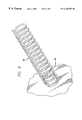
- FIG. 5 is an enlarged perspective view, in an open or disassembled relationship, of a portion of a pogo stick shown in FIG. 4 and shows the features which distinguish the embodiment of the invention shown in FIGS. 4 and 5 from the embodiment of the invention shown in FIGS. 1 - 3 ;
- FIG. 6 is a fragmentary sectional view taken substantially on the line 6 — 6 of FIG. 5 and shows additional details of a switch shown in FIG. 5;
- FIG. 7 is an elevational view of a second embodiment, actually constituting a preferred embodiment, of a pogo stick which incorporates the features of the embodiment shown in FIGS. 1 - 6 .
- FIGS. 1 - 3 show a pogo stick, generally indicated at 10 , constituting one embodiment of the invention.
- the pogo stick 10 includes a housing 12 preferably having a hollow tubular form.
- a handle 14 is disposed at the upper end of the housing and a foot rest or foot stand 16 is disposed on the housing at a position near the lower end of the housing.
- Covers or handle bars 18 may be provided at the opposite ends of the handle 14 to facilitate a comfortable gripping of the handle by a child on the pogo stick.
- An actuating member 22 extends into the housing 12 through an opening 24 at the bottom of the housing.
- a cover 26 is disposed on the actuating member 22 at the bottom of the actuating member to cushion the impact of the actuating member against the support surface such as the ground.
- the actuating member 22 has a cap 28 which causes the actuating member to be retained within the housing.
- An internal flange 30 is disposed in the housing 12 to guide the movement of the actuating member in the housing.
- a restraining member such as a spring 32 , preferably helical, is disposed on the actuating member 22 in the housing 12 between the cap 28 and the internal flange 30 .
- a casing 34 is supported by the housing 12 .
- the casing 34 may be supported at any suitable position on the housing. In the embodiment shown in FIGS. 1 - 3 , the casing 34 is shown as being disposed at an intersection between the housing 12 and the handle 14 .
- a microprocessor 36 is disposed within the casing 34 .
- the microprocessor 36 includes a counter 38 which is constructed to count to a particular value (e.g. 20) and then recycle for the initiation of a new count.
- Buttons 40 a , 40 b and 40 c may be disposed on the panel for varying, when depressed, the particular count to individual values (e.g. 10, 20 and 30) before initiating a new count.
- a button 42 may also be disposed on the casing 34 for providing a reset of the count in the counter 38 to 0, when depressed, before the particular count has been reached.
- a support 44 is provided in the casing 34 .
- a support rod 46 extends from the support 44 and holds a resilient electrically conductive member such as a helical spring 48 .
- a portion of the spring 48 extends beyond the support rod 46 for a pivotal movement vertically relative to the rod when the actuating member 22 impinges on the ground.
- a stationary electrically conductive contact 50 is disposed to engage the spring 48 when the spring is pivoted by the impingement of the actuating member 22 on the ground.
- the spring 48 and the electrical contact 50 accordingly constitute a switch having open and closed relationships.
- the spring 48 and the stationary electrical contact 50 are connected to the microprocessor 36 .
- An indicator such as a speaker 52 is also included in the casing 34 and is connected to the microprocessor 36 . It should be appreciated that the indicator may have forms other than the speaker 52 without departing from the scope of the invention.
- the indicator 52 may provide a visual flash of light every time that the count in the counter 38 reaches the particular value.
- a liquid crystal display (LCD) 54 may also be included in the casing 34 and may be connected to the microprocessor 36 .
- the LCD 54 may provide a unique display such as a display of musical notes every time that the count in the counter 38 reaches the particular value.
- the LCD may indicate a congratulatory message such as “good job” every time that the count in the counter 38 reaches the particular value.
- a child rests his or her feet on the foot rest or foot stand 16 and grasps the covers or handle bars 18 at the opposite ends of the handle 14 .
- the child then operates the pogo stick 10 to provide progressive hops along the ground. Every time that the actuating member 22 impinges on the ground, the spring 32 becomes constrained to provide energy for the next hop along the ground. The constraint of the spring 32 becomes relieved when the actuating member 22 leaves the ground in the next hop.
- the switch formed by the spring 48 and the contact 50 closes.
- the counter 38 in the microprocessor 36 counts the number of times that the switch closes.
- the speaker emits a distinctive sound. This sound may provide an aural indication that the child has been successful in hopping the particular number of successive times. If the child has not been successful in hopping the particular number of successive times, the count in the counter 38 can be reset to zero by depressing the button 42 .
- FIGS. 4, 5 and 6 illustrate another embodiment, generally indicated at 60 , of the invention.
- the casing 34 is disposed between the handle 14 and the housing 12 .
- an electrically conductive spring 62 is disposed on a non-conductive stud 64 for pivotal movement vertically into engagement with a stationary electrically conductive contact 66 .
- the spring 62 and the contact 66 accordingly define a switch having open and closed relationships.
- Another contact 68 is disposed on the other side of the spring 62 from the contact 66 to limit the pivotable movement of the spring in this direction.
- FIG. 7 is an elevational view of a pogo stick generally indicated at 100 and constituting a preferred embodiment of the invention.
- the embodiment shown in FIG. 7 incorporates all of the features of the embodiment shown in FIGS. 1 - 6 .
- a casing 102 is provided to replace the casing 34 .
- the casing 102 is immediately below the handle 14 and is in aligned relationship with the housing. This facilitates the balance in the pogo stick and facilitates the successful operation of the pogo stick by youngsters. All of the components specified to be included in the casing 34 are included in the casing 102 .
Abstract
A pogo stick includes (a) a housing, (b) a member movable within the housing, (c) a spring retained at opposite ends by the housing and the member and compressible upon the actuation of the member to a support surface (e.g. ground) and expansible upon the movement of the member from the support surface, (d) a handle on the housing near the housing top and (e) a foot rest on the housing near the housing bottom. A switch normally in an open relationship is operative (a) to a closed relationship upon the actuation of the member to the support surface and (b) to an open relationship upon a movement of the member from the support surface. The switch includes a resilient electrically conductive element and a stationary electrically conductive element normally defining an open relationship. The resilient member is movable in response to the member actuation to the support surface to engage the stationary element and to provide a switch operation in the closed relationship. The resilient element extends beyond a supporting stud for pivotable movement relative to the stud and the stationary element to engage the stationary element upon the member actuation to the support surface. An indicator responsive to the switch operation provides an indication (e.g. distinctive sound) after each particular number of switch operations. The switch and the indicator are disposed within a casing supported by the housing. A reset within the casing is connected to the counter to initialize the count when manually operated.
Description
This invention relates to a pogo stick and, more particularly, to a pogo stick which provides a distinctive indication (e.g. a distinctive sound) when operated.
Pogo sticks have been in existence for some time and provide a distinct challenge to children, particularly to children of advanced age, when operated. To operate a pogo stick, a child steps on a foot rest on a housing on the pogo stick, grasps a handle on the housing and hops through successive iterations to progressive positions until the child loses his or her balance. It is a challenge to a child to be able to hop on the pogo stick through a number of successive iterations without having to jump from the pogo stick because of a loss of balance.
In spite of the challenges offered by the pogo stick, children are constantly looking for new sensations while operating the pogo stick. These new sensations enhance the thrill which the children experience while operating the pogo stick. Such new sensations would be particularly desirable if they provide in some way an instantaneous indication of the number of successive hops experienced by a child during an operation of the pogo stick before the child loses his or her balance.
In one embodiment of the invention, a pogo stick includes (a) a housing, (b) a member movable within the housing, (c) a spring retained at opposite ends by the housing and the member and compressible upon the actuation of the member to a support surface (e.g. ground) and expansible upon the movement of the member from the support surface, (d) a handle on the housing near the housing top and (e) a foot rest on the housing near the housing bottom. A switch normally in an open relationship is operative to (a) a closed relationship upon the actuation of the member to the support surface and (b) an open relationship upon a movement of the member from the support surface. The switch includes a resilient electrically conductive element and a stationary electrically conductive element normally defining an open relationship. The resilient member is movable in response to the member actuation to the support surface to engage the stationary element and to provide a switch operation in the closed relationship.
The resilient element extends beyond a supporting stud for pivotable movement relative to the stud and the stationary element to engage the stationary clement upon the member actuation to the support surface. An indicator responsive to the switch operation provides an indication (e.g. distinctive sound) after each particular number of switch operations. The switch and the indicator are disposed within a casing supported by the housing. A reset within the casing is connected to the counter to initialize the count when manually operated.
In the drawings:
FIG. 1 is a simplified sectional view in elevation of a pogo stick constituting one embodiment of the invention;
FIG. 2 is an enlarged sectional view in elevation, with the cover removed, of a portion of the pogo stick shown in FIG. 1, this portion being operative to count the number of hops or actuations provided by a child to a support surface (e.g. the ground) before the child loses his or her balance and has to alight from the pogo stick;
FIG. 3 is an enlarged elevational view of the portion of the pogo stick shown in FIG. 2 with the cover disposed on such portion;
FIG. 4 is a fragmentary sectional view in elevation of a pogo stick constituting a second embodiment of the invention;
FIG. 5 is an enlarged perspective view, in an open or disassembled relationship, of a portion of a pogo stick shown in FIG. 4 and shows the features which distinguish the embodiment of the invention shown in FIGS. 4 and 5 from the embodiment of the invention shown in FIGS. 1-3;
FIG. 6 is a fragmentary sectional view taken substantially on the line 6—6 of FIG. 5 and shows additional details of a switch shown in FIG. 5; and
FIG. 7 is an elevational view of a second embodiment, actually constituting a preferred embodiment, of a pogo stick which incorporates the features of the embodiment shown in FIGS. 1-6.
FIGS. 1-3 show a pogo stick, generally indicated at 10, constituting one embodiment of the invention. The pogo stick 10 includes a housing 12 preferably having a hollow tubular form. A handle 14 is disposed at the upper end of the housing and a foot rest or foot stand 16 is disposed on the housing at a position near the lower end of the housing. Covers or handle bars 18 may be provided at the opposite ends of the handle 14 to facilitate a comfortable gripping of the handle by a child on the pogo stick.
An actuating member 22 extends into the housing 12 through an opening 24 at the bottom of the housing. A cover 26 is disposed on the actuating member 22 at the bottom of the actuating member to cushion the impact of the actuating member against the support surface such as the ground. The actuating member 22 has a cap 28 which causes the actuating member to be retained within the housing. An internal flange 30 is disposed in the housing 12 to guide the movement of the actuating member in the housing. A restraining member such as a spring 32, preferably helical, is disposed on the actuating member 22 in the housing 12 between the cap 28 and the internal flange 30.
A casing 34 is supported by the housing 12. The casing 34 may be supported at any suitable position on the housing. In the embodiment shown in FIGS. 1-3, the casing 34 is shown as being disposed at an intersection between the housing 12 and the handle 14. A microprocessor 36 is disposed within the casing 34. The microprocessor 36 includes a counter 38 which is constructed to count to a particular value (e.g. 20) and then recycle for the initiation of a new count. Buttons 40 a, 40 b and 40 c may be disposed on the panel for varying, when depressed, the particular count to individual values (e.g. 10, 20 and 30) before initiating a new count. A button 42 may also be disposed on the casing 34 for providing a reset of the count in the counter 38 to 0, when depressed, before the particular count has been reached.
A support 44 is provided in the casing 34. A support rod 46 extends from the support 44 and holds a resilient electrically conductive member such as a helical spring 48. A portion of the spring 48 extends beyond the support rod 46 for a pivotal movement vertically relative to the rod when the actuating member 22 impinges on the ground. A stationary electrically conductive contact 50 is disposed to engage the spring 48 when the spring is pivoted by the impingement of the actuating member 22 on the ground. The spring 48 and the electrical contact 50 accordingly constitute a switch having open and closed relationships. The spring 48 and the stationary electrical contact 50 are connected to the microprocessor 36.
An indicator such as a speaker 52 is also included in the casing 34 and is connected to the microprocessor 36. It should be appreciated that the indicator may have forms other than the speaker 52 without departing from the scope of the invention. For example, the indicator 52 may provide a visual flash of light every time that the count in the counter 38 reaches the particular value. A liquid crystal display (LCD) 54 may also be included in the casing 34 and may be connected to the microprocessor 36. The LCD 54 may provide a unique display such as a display of musical notes every time that the count in the counter 38 reaches the particular value. Alternatively, the LCD may indicate a congratulatory message such as “good job” every time that the count in the counter 38 reaches the particular value.
A child rests his or her feet on the foot rest or foot stand 16 and grasps the covers or handle bars 18 at the opposite ends of the handle 14. The child then operates the pogo stick 10 to provide progressive hops along the ground. Every time that the actuating member 22 impinges on the ground, the spring 32 becomes constrained to provide energy for the next hop along the ground. The constraint of the spring 32 becomes relieved when the actuating member 22 leaves the ground in the next hop.
Every time that the pogo stick 10 impinges on the ground, the switch formed by the spring 48 and the contact 50 closes. The counter 38 in the microprocessor 36 counts the number of times that the switch closes. When the count in the counter 38 reaches the particular value, the speaker emits a distinctive sound. This sound may provide an aural indication that the child has been successful in hopping the particular number of successive times. If the child has not been successful in hopping the particular number of successive times, the count in the counter 38 can be reset to zero by depressing the button 42.
FIGS. 4, 5 and 6 illustrate another embodiment, generally indicated at 60, of the invention. In the embodiment 60, the casing 34 is disposed between the handle 14 and the housing 12. Furthermore, an electrically conductive spring 62 is disposed on a non-conductive stud 64 for pivotal movement vertically into engagement with a stationary electrically conductive contact 66. The spring 62 and the contact 66 accordingly define a switch having open and closed relationships. Another contact 68 is disposed on the other side of the spring 62 from the contact 66 to limit the pivotable movement of the spring in this direction.
FIG. 7 is an elevational view of a pogo stick generally indicated at 100 and constituting a preferred embodiment of the invention. The embodiment shown in FIG. 7 incorporates all of the features of the embodiment shown in FIGS. 1-6. However, a casing 102 is provided to replace the casing 34. As will be seen, the casing 102 is immediately below the handle 14 and is in aligned relationship with the housing. This facilitates the balance in the pogo stick and facilitates the successful operation of the pogo stick by youngsters. All of the components specified to be included in the casing 34 are included in the casing 102.
Although this invention has been disclosed and illustrated with reference to particular embodiments, the principles involved are capable of being used in numerous other embodiments which will be apparent to persons of ordinary skill in the art. The invention is, therefore, to be limited only as indicated by the scope of the appended claims.
Claims (24)
1. In combination for use in a pogo stick,
a housing,
a handle disposed at the top of the housing and defining a balanced relationship with the housing,
a foot rest disposed at an intermediate position on the housing and defining a balanced relationship with the housing,
an actuator extending into the housing in an aligned relationship with the housing for movement in the housing in accordance with the actuation of the pogo stick onto the ground and the subsequent release of the pogo stick from the ground,
a casing disposed between the housing and the handle in an aligned relationship with the housing,
a spring disposed in the housing and operatively coupled to the actuator to become constrained upon the actuation of the pogo stick onto the ground and to become released of the constraint upon the release of the pogo stick from the ground,
a resilient member disposed in the casing in a first position and responsive to each actuation of the actuator onto the ground to become moved to a second position and responsive to each release of the actuator from the ground to become returned to the first position,
a stationary contact disposed in the casing,
a switch disposed in the casing and including the resilient member and the stationary contact and having first and second states of operation and operable in the first state with the resilient member in the first position and operable in the second state with the resilient member in the second position,
a counter disposed in the casing for counting the number of operations of the resilient member in the second state, and
a member disposed in the casing for providing a sensory indication when the count in the counter has reached a particular value.
2. In a combination as set forth in claim 1,
the casing being supported on the housing for holding the resilient member, the switch, the stationary contact, the counter and the indicator in the casing,
the casing having a balanced relationship with respect to the handle and the housing.
3. In a combination as set forth in claim 1 wherein
the indicator provides a distinctive sound upon each count in the counter to the particular value.
4. In a combination as set forth in claim 1 wherein
means are included on the casing for setting the counter to count to any desired value to provide the sensory indication by the sensory member.
5. In a combination as set forth in claim 1 wherein
the casing is disposed on the housing between the housing and the handle and holds the resilient member, the switch, the counter and the indicator and wherein
the indicator provides a distinctive sound upon each count to the particular value.
6. In a combination as set forth in claim 5 wherein
a reset is provided on the casing to reset the count in the counter to an initializing value.
7. In combination for use in a pogo stick,
a housing operable to provide a bouncing movement along a support surface,
a member disposed within the housing in a vertically aligned relationship with the housing and actuatable between a first relationship and a second relationship upon each bouncing movement of the pogo stick on the support surface,
a handle supported by the housing in a balanced relationship with the housing;
a casing supported by the housing in a vertically aligned relationship with the housing,
a counter disposed within the casing for counting the number of actuations of the member, and
an energizable member disposed within the casing and operatively coupled to the counter for providing a sensory indication upon each count by the counter to a particular value.
8. In a combination as set forth in claim 7 wherein
the casing has a balanced relationship with the housing.
9. In a combination as set forth in claim 7 wherein
the energizable member provides a distinctive sound upon each occurence of a particular mumber of bouncing movements of the member on the support surface.
10. In a combination as set forth in claim 7 wherein
a resilient spring is disposed within the casing and is actuatable in a vertical direction upon each engagement of the housing with the support surface and wherein
the resilient spring is included in a switch disposed within the casing and having open and closed states and normally operable in the open state and operable in the closed state upon each actuation of the actuatable member and wherein
the counter counts the number of times that the switch becomes operative in the closed state.
11. In a combination as set forth in claim 10 wherein
the counter is included in a microprocessor which is disposed within the casing and which provides for a count by the counter to the particular value and a resetting of the counter to an initializing value upon each count by the counter to the particular value and an energizing of the energizable member to provide the sensory indication upon each count by the counter to the particular value.
12. In a combination as set forth in claim 11 wherein
the energizable member provides a distinctive sound upon each occurrence of a particular number of bouncing movements of the member on the support surface.
13. In a combination as set forth in claim 8 wherein
at least one member is disposed on the casing and is manually actuatable to set the counter to one of a plurality of different values.
14. In a combination as set forth in claim 12 wherein
at least one member is disposed on the casing and is manually actuatable to set the counter to one of a plurality of different values.
15. In a combination as set forth in claim 8 wherein
the casing is disposed between the housing and the handle in contiguous relationship to the handle and is supported by the housing and wherein
a reset is provided on the casing for manual operation and is operatively coupled to the counter to reset the counter to an initializing value when manually operated.
16. In combination for use in a pogo stick,
a housing disposed in a particular direction,
a member movable within the housing in the particular direction,
a spring disposed within the housing and retained at opposite ends by the housing and the member and compressible in the particular direction upon the actuation of the member to a support surface and expansible in the particular direction upon the movement of the pogo stick from the support surface,
a handle on the housing at a position near the top of the housing, the handle being disposed in a balanced relationship to the housing,
a foot rest on the housing at a position near the bottom of the housing, the footrest being disposed in a balanced relationship to the housing,
a casing disposed between the handle and the housing in an aligned relationship with the housing,
a switch disposed in the casing and having open and closed relationships and normally operable in the open relationship and responsive to the actuation of the housing to the support surface to become operative in the closed relationship and responsive to the movement of the housing from the support surface to become operative in the opened relationship, and
an indicator disposed in the casing and responsive to the operations of the switch in the closed relationship to provide a sensory indication after each particular number of operations of the switch in the closed relationship.
17. In a combination as set forth in claim 16 wherein
the switch includes a resilient electrically conductive element disposed in the casing and a stationary electrically conductive element disposed in the casing and normally spaced from each other in the particular direction to define the open relationship of the switch and wherein the resilient electrically conductive element is movable in the particular direction in response to the actuation of the housing to the support surface to engage the stationary electrically conductive element in the particular direction and to provide an operation of the switch in the closed relationship.
18. In a combination as set forth in claim 16 wherein
the switch includes a resilient electrically conductive element disposed within the housing and a stationary electrically conductive element disposed within the casing and wherein the casing is supported by the housing in a balanced relationship to the housing.
19. In a combination as set forth in claim 16 wherein
the casing is disposed between the housing and the handle and is supported by the housing.
20. In a combination as set forth in claim 18 wherein
a reset is disposed on the casing for manual operation and wherein
a counter is disposed within the casing to count the number of closures of the switch and wherein
the reset is connected in the casing to the counter to initialize the count in the counter when the reset is manually operated.
21. In a combination as set forth in claim 17 wherein
the resilient electrically conductive element is supported by a stud disposed in the casing and wherein the resilient electrically conductive element extends in the casing beyond the stud for pivotable movement in the particular direction relative to the stud and the stationary electrically conductive element to engage the stationary electrically conductive element upon the actuation of the housing to the support surface.
22. In a combination as set forth in claim 21 wherein
the stationary electrically conductive element is displaced in the particular direction in the casing on one side of the resilient electrically conductive element in the casing and wherein another stationary element is displaced in the particular direction in the casing on the other side of the resilient electrically conductive element in the casing to limit the pivotable movement of the resilient electrically conductive element in the particular direction in the casing when the member moves from the support surface.
23. In a combination as set forth in claim 22 wherein
the casing is supported by the housing and wherein the indicator provides a distinctive sound when it is energized.
24. In a combination as set forth in claim 23 wherein
a reset is disposed on the casing for manual operation and wherein a counter is disposed within the casing to count the number of closures of the switch and wherein the reset is connected in the casing to the counter to initialize the count in the counter when the reset is manually operated.
Priority Applications (1)
| Application Number | Priority Date | Filing Date | Title |
|---|---|---|---|
| US09/159,291 US6168555B1 (en) | 1998-09-23 | 1998-09-23 | Pogo stick providing a distinctive indication when operated |
Applications Claiming Priority (1)
| Application Number | Priority Date | Filing Date | Title |
|---|---|---|---|
| US09/159,291 US6168555B1 (en) | 1998-09-23 | 1998-09-23 | Pogo stick providing a distinctive indication when operated |
Publications (1)
| Publication Number | Publication Date |
|---|---|
| US6168555B1 true US6168555B1 (en) | 2001-01-02 |
Family
ID=22571922
Family Applications (1)
| Application Number | Title | Priority Date | Filing Date |
|---|---|---|---|
| US09/159,291 Expired - Fee Related US6168555B1 (en) | 1998-09-23 | 1998-09-23 | Pogo stick providing a distinctive indication when operated |
Country Status (1)
| Country | Link |
|---|---|
| US (1) | US6168555B1 (en) |
Cited By (24)
| Publication number | Priority date | Publication date | Assignee | Title |
|---|---|---|---|---|
| US20030092537A1 (en) * | 2001-10-19 | 2003-05-15 | Spencer Bruce L. | Pneumatic pogo stick |
| US20030096678A1 (en) * | 2001-11-20 | 2003-05-22 | Wong Jon G. | Jumping stick |
| US6589140B1 (en) * | 2002-01-04 | 2003-07-08 | Cheng-Hsiung Hsu | Pogo stick with a counting mechanism |
| USD487484S1 (en) | 2002-04-15 | 2004-03-09 | J. M. Originals, Inc. | Foam pogo stick |
| KR20040042074A (en) * | 2002-11-12 | 2004-05-20 | 김정화 | Solenoid Assisted Jumping Stick |
| KR20040043718A (en) * | 2002-11-16 | 2004-05-27 | 김정화 | Solenoid Assisted Jumping Stick |
| US20040235624A1 (en) * | 2003-05-20 | 2004-11-25 | Bruce Gregory M. | Exercise device |
| US6964634B2 (en) | 2001-10-15 | 2005-11-15 | Mattel, Inc. | Jumping device with convertible stabilizing base |
| US20070042874A1 (en) * | 2005-08-19 | 2007-02-22 | J.M. Originals, Inc. | Light up bouncing apparatus |
| US20070042875A1 (en) * | 2005-08-19 | 2007-02-22 | J.M. Originals, Inc. | Light up bouncing and entertainment apparatuses |
| US20070117444A1 (en) * | 2005-11-18 | 2007-05-24 | Panduit Corp. | Smart cable provisioning for a patch cord management system |
| EP1790391A1 (en) * | 2005-11-22 | 2007-05-30 | H Grossman Limited | Pogo stick |
| US20100157516A1 (en) * | 2008-12-22 | 2010-06-24 | Panduit Corp. | Physical infrastructure management system |
| US20100184323A1 (en) * | 2008-11-12 | 2010-07-22 | Panduit Corp. | Patch Cord with Insertion Detection and Light Illumination Capabilities |
| US20100210134A1 (en) * | 2009-02-19 | 2010-08-19 | Panduit Corp. | Cross connect patch guidance system |
| US20100267274A1 (en) * | 2007-10-19 | 2010-10-21 | Panduit Corp | Communication port identification system |
| US7938700B2 (en) | 2008-02-21 | 2011-05-10 | Panduit Corp. | Intelligent inter-connect and cross-connect patching system |
| CN104174140A (en) * | 2014-09-09 | 2014-12-03 | 谢伟民 | Arm-assisting kangaroo-simulation bouncing device |
| USD740897S1 (en) * | 2014-04-03 | 2015-10-13 | Heinz Richard Miltner | Spring loaded weight stack selector pin |
| US20170065853A1 (en) * | 2015-09-09 | 2017-03-09 | Ferris Marketing, Inc. | Jumping device |
| USD804584S1 (en) * | 2015-08-20 | 2017-12-05 | Troy Miles | Chiropractic adjusting toy for kids |
| US10245467B2 (en) | 2014-07-01 | 2019-04-02 | Vurtego, LLC | Piston configurations for pneumatic pogo stick |
| CN112704843A (en) * | 2020-12-07 | 2021-04-27 | 武汉体育学院 | Device for intelligently assisting obesity teenagers to lose weight |
| USD965690S1 (en) * | 2021-03-05 | 2022-10-04 | Xiantao Xu | Pogo stick |
Citations (4)
| Publication number | Priority date | Publication date | Assignee | Title |
|---|---|---|---|---|
| US2793036A (en) * | 1955-02-18 | 1957-05-21 | George B Hansburg | Pogo stick |
| US4390178A (en) * | 1980-06-20 | 1983-06-28 | Elliot Rudell | Pivotal jumping stick |
| US4526036A (en) * | 1983-12-30 | 1985-07-02 | Morrison Thomas R | Cadence meter |
| US5857939A (en) * | 1997-06-05 | 1999-01-12 | Talking Counter, Inc. | Exercise device with audible electronic monitor |
-
1998
- 1998-09-23 US US09/159,291 patent/US6168555B1/en not_active Expired - Fee Related
Patent Citations (4)
| Publication number | Priority date | Publication date | Assignee | Title |
|---|---|---|---|---|
| US2793036A (en) * | 1955-02-18 | 1957-05-21 | George B Hansburg | Pogo stick |
| US4390178A (en) * | 1980-06-20 | 1983-06-28 | Elliot Rudell | Pivotal jumping stick |
| US4526036A (en) * | 1983-12-30 | 1985-07-02 | Morrison Thomas R | Cadence meter |
| US5857939A (en) * | 1997-06-05 | 1999-01-12 | Talking Counter, Inc. | Exercise device with audible electronic monitor |
Cited By (57)
| Publication number | Priority date | Publication date | Assignee | Title |
|---|---|---|---|---|
| US6964634B2 (en) | 2001-10-15 | 2005-11-15 | Mattel, Inc. | Jumping device with convertible stabilizing base |
| US20030092537A1 (en) * | 2001-10-19 | 2003-05-15 | Spencer Bruce L. | Pneumatic pogo stick |
| US7011608B2 (en) | 2001-10-19 | 2006-03-14 | Spencer Bruce L | Pneumatic pogo stick |
| US20050277522A1 (en) * | 2001-11-20 | 2005-12-15 | Wong Jon G | Jumping stick |
| US20030096678A1 (en) * | 2001-11-20 | 2003-05-22 | Wong Jon G. | Jumping stick |
| US6932746B2 (en) * | 2001-11-20 | 2005-08-23 | Jon G. Wong | Jumping stick |
| US6589140B1 (en) * | 2002-01-04 | 2003-07-08 | Cheng-Hsiung Hsu | Pogo stick with a counting mechanism |
| USD487484S1 (en) | 2002-04-15 | 2004-03-09 | J. M. Originals, Inc. | Foam pogo stick |
| KR20040042074A (en) * | 2002-11-12 | 2004-05-20 | 김정화 | Solenoid Assisted Jumping Stick |
| KR20040043718A (en) * | 2002-11-16 | 2004-05-27 | 김정화 | Solenoid Assisted Jumping Stick |
| US20040235624A1 (en) * | 2003-05-20 | 2004-11-25 | Bruce Gregory M. | Exercise device |
| US8021284B2 (en) | 2003-05-20 | 2011-09-20 | Edison Nation, Llc | Exercise device |
| US20080045389A1 (en) * | 2003-05-20 | 2008-02-21 | Gregory Bruce | Exercise device |
| US7361126B2 (en) * | 2003-05-20 | 2008-04-22 | Bruce Gregory M | Exercise device |
| US20070042874A1 (en) * | 2005-08-19 | 2007-02-22 | J.M. Originals, Inc. | Light up bouncing apparatus |
| US20070042875A1 (en) * | 2005-08-19 | 2007-02-22 | J.M. Originals, Inc. | Light up bouncing and entertainment apparatuses |
| WO2007024629A2 (en) * | 2005-08-19 | 2007-03-01 | J.M. Originals, Inc. | Light up bouncing and entertainment apparatuses |
| WO2007024629A3 (en) * | 2005-08-19 | 2007-04-19 | J M Originals Inc | Light up bouncing and entertainment apparatuses |
| US7997952B2 (en) | 2005-08-19 | 2011-08-16 | J.M. Originals, Inc. | Light up bouncing and entertainment apparatuses |
| US7448987B2 (en) * | 2005-08-19 | 2008-11-11 | J.M. Originals, Inc. | Light up bouncing and entertainment apparatuses |
| US7381165B2 (en) * | 2005-08-19 | 2008-06-03 | J.M. Originals, Inc. | Light up bouncing apparatus |
| US20110028029A1 (en) * | 2005-11-18 | 2011-02-03 | Panduit Corp. | Smart Cable Provisioning For a Patch Cord Management System |
| US7811119B2 (en) * | 2005-11-18 | 2010-10-12 | Panduit Corp. | Smart cable provisioning for a patch cord management system |
| US8197280B2 (en) * | 2005-11-18 | 2012-06-12 | Panduit Corp. | Smart cable provisioning for a patch cord management system |
| US20070117444A1 (en) * | 2005-11-18 | 2007-05-24 | Panduit Corp. | Smart cable provisioning for a patch cord management system |
| US8118716B2 (en) * | 2005-11-22 | 2012-02-21 | H. Grossman Limited | Pogo stick |
| US20070270289A1 (en) * | 2005-11-22 | 2007-11-22 | Martin Grossman | Pogo stick |
| EP1790391A1 (en) * | 2005-11-22 | 2007-05-30 | H Grossman Limited | Pogo stick |
| US20100267274A1 (en) * | 2007-10-19 | 2010-10-21 | Panduit Corp | Communication port identification system |
| US8477031B2 (en) | 2007-10-19 | 2013-07-02 | Panduit Corp. | Communication port identification system |
| US7938700B2 (en) | 2008-02-21 | 2011-05-10 | Panduit Corp. | Intelligent inter-connect and cross-connect patching system |
| US8715001B2 (en) | 2008-02-21 | 2014-05-06 | Panduit Corp. | Intelligent inter-connect and cross-connect patching system |
| US8419465B2 (en) | 2008-02-21 | 2013-04-16 | Panduit Corp. | Intelligent inter-connect and cross-connect patching system |
| US9866458B2 (en) | 2008-02-21 | 2018-01-09 | Panduit Corp. | Intelligent inter-connect and cross-connect patching system |
| US8246397B2 (en) | 2008-02-21 | 2012-08-21 | Panduit Corp. | Intelligent inter-connect and cross-connect patching system |
| US8414319B2 (en) | 2008-11-12 | 2013-04-09 | Panduit Corp. | Patch cord with insertion detection and light illumination capabilities |
| US8267706B2 (en) | 2008-11-12 | 2012-09-18 | Panduit Corp. | Patch cord with insertion detection and light illumination capabilities |
| US20100184323A1 (en) * | 2008-11-12 | 2010-07-22 | Panduit Corp. | Patch Cord with Insertion Detection and Light Illumination Capabilities |
| US8708724B2 (en) | 2008-11-12 | 2014-04-29 | Panduit Corp. | Patch cord insertion detection and light illumination capabilities |
| US9026486B2 (en) | 2008-12-22 | 2015-05-05 | Panduit Corp. | Physical infrastructure management system |
| US20100157516A1 (en) * | 2008-12-22 | 2010-06-24 | Panduit Corp. | Physical infrastructure management system |
| US8719205B2 (en) | 2008-12-22 | 2014-05-06 | Panduit Corp. | Physical infrastructure management system |
| US10516580B2 (en) | 2008-12-22 | 2019-12-24 | Panduit Corp. | Physical infrastructure management system |
| US8306935B2 (en) | 2008-12-22 | 2012-11-06 | Panduit Corp. | Physical infrastructure management system |
| US8382511B2 (en) | 2009-02-19 | 2013-02-26 | Panduit Corp. | Cross connect patch guidance system |
| US20100210134A1 (en) * | 2009-02-19 | 2010-08-19 | Panduit Corp. | Cross connect patch guidance system |
| US8721360B2 (en) | 2009-02-19 | 2014-05-13 | Panduit Corp. | Methods for patch cord guidance |
| US8128428B2 (en) | 2009-02-19 | 2012-03-06 | Panduit Corp. | Cross connect patch guidance system |
| USD740897S1 (en) * | 2014-04-03 | 2015-10-13 | Heinz Richard Miltner | Spring loaded weight stack selector pin |
| US20190255387A1 (en) * | 2014-07-01 | 2019-08-22 | Vurtego, LLC | Piston configurations for pneumatic pogo stick |
| US10245467B2 (en) | 2014-07-01 | 2019-04-02 | Vurtego, LLC | Piston configurations for pneumatic pogo stick |
| CN104174140A (en) * | 2014-09-09 | 2014-12-03 | 谢伟民 | Arm-assisting kangaroo-simulation bouncing device |
| USD804584S1 (en) * | 2015-08-20 | 2017-12-05 | Troy Miles | Chiropractic adjusting toy for kids |
| US20170065853A1 (en) * | 2015-09-09 | 2017-03-09 | Ferris Marketing, Inc. | Jumping device |
| CN112704843A (en) * | 2020-12-07 | 2021-04-27 | 武汉体育学院 | Device for intelligently assisting obesity teenagers to lose weight |
| CN112704843B (en) * | 2020-12-07 | 2022-03-25 | 武汉体育学院 | Device for intelligently assisting obesity teenagers to lose weight |
| USD965690S1 (en) * | 2021-03-05 | 2022-10-04 | Xiantao Xu | Pogo stick |
Similar Documents
| Publication | Publication Date | Title |
|---|---|---|
| US6168555B1 (en) | Pogo stick providing a distinctive indication when operated | |
| US5662466A (en) | Safety structure for electronic lighters | |
| US4056265A (en) | Machine for indoor running | |
| EP0725329B1 (en) | Collapsible pointing stick apparatus for a portable computer | |
| US3856304A (en) | Boxing game | |
| US4783074A (en) | Puzzle with timer controlled disassembling means | |
| JP2012034989A (en) | Game machine | |
| US4705268A (en) | Toy exercizing machine for children | |
| US3817519A (en) | Play control device for amusement game | |
| JP2008295666A (en) | Game machine | |
| JP2000293298A (en) | Operation device and its controlling method | |
| JPH11156047A (en) | Simulation game device, operation error evaluation and recording medium | |
| US20070270289A1 (en) | Pogo stick | |
| US2435141A (en) | Amusement game | |
| JP2019010390A (en) | Game machine | |
| US593056A (en) | Joseph n | |
| JPH07185126A (en) | Game machine | |
| US6589140B1 (en) | Pogo stick with a counting mechanism | |
| US20040214691A1 (en) | Pogo sticks | |
| JP2009045270A (en) | Game ball shooting adjustment device of game machine | |
| US6861962B2 (en) | Electronic pinball | |
| US858666A (en) | Game apparatus. | |
| US6550767B2 (en) | Children's toy | |
| JP7309181B2 (en) | game machine | |
| JP2011024833A (en) | Game machine |
Legal Events
| Date | Code | Title | Description |
|---|---|---|---|
| AS | Assignment |
Owner name: SPORT FUN, INC., CALIFORNIA Free format text: ASSIGNMENT OF ASSIGNORS INTEREST;ASSIGNORS:FETTERLEIGH, DALE MICHAEL;GOTTLIEB-MYERS, KAREN;REEL/FRAME:009768/0018 Effective date: 19980923 |
|
| FEPP | Fee payment procedure |
Free format text: PAYOR NUMBER ASSIGNED (ORIGINAL EVENT CODE: ASPN); ENTITY STATUS OF PATENT OWNER: SMALL ENTITY |
|
| FPAY | Fee payment |
Year of fee payment: 4 |
|
| REMI | Maintenance fee reminder mailed | ||
| LAPS | Lapse for failure to pay maintenance fees | ||
| STCH | Information on status: patent discontinuation |
Free format text: PATENT EXPIRED DUE TO NONPAYMENT OF MAINTENANCE FEES UNDER 37 CFR 1.362 |
|
| FP | Lapsed due to failure to pay maintenance fee |
Effective date: 20090102 |