US6152558A - Ink jet printer - Google Patents
Ink jet printer Download PDFInfo
- Publication number
- US6152558A US6152558A US09/020,419 US2041998A US6152558A US 6152558 A US6152558 A US 6152558A US 2041998 A US2041998 A US 2041998A US 6152558 A US6152558 A US 6152558A
- Authority
- US
- United States
- Prior art keywords
- ink
- ink tank
- carriage
- tanks
- tank
- Prior art date
- Legal status (The legal status is an assumption and is not a legal conclusion. Google has not performed a legal analysis and makes no representation as to the accuracy of the status listed.)
- Expired - Lifetime
Links
- 230000000295 complement effect Effects 0.000 claims abstract description 3
- 238000003780 insertion Methods 0.000 claims description 3
- 230000037431 insertion Effects 0.000 claims description 3
- 239000000976 ink Substances 0.000 description 254
- 238000010276 construction Methods 0.000 description 9
- 239000003086 colorant Substances 0.000 description 7
- 238000012986 modification Methods 0.000 description 2
- 230000004048 modification Effects 0.000 description 2
- 238000007789 sealing Methods 0.000 description 2
- 230000004888 barrier function Effects 0.000 description 1
- 230000003247 decreasing effect Effects 0.000 description 1
- 230000001627 detrimental effect Effects 0.000 description 1
- 238000001035 drying Methods 0.000 description 1
- 239000000463 material Substances 0.000 description 1
- 239000012858 resilient material Substances 0.000 description 1
- 230000000630 rising effect Effects 0.000 description 1
Images


Classifications
-
- B—PERFORMING OPERATIONS; TRANSPORTING
- B41—PRINTING; LINING MACHINES; TYPEWRITERS; STAMPS
- B41J—TYPEWRITERS; SELECTIVE PRINTING MECHANISMS, i.e. MECHANISMS PRINTING OTHERWISE THAN FROM A FORME; CORRECTION OF TYPOGRAPHICAL ERRORS
- B41J2/00—Typewriters or selective printing mechanisms characterised by the printing or marking process for which they are designed
- B41J2/005—Typewriters or selective printing mechanisms characterised by the printing or marking process for which they are designed characterised by bringing liquid or particles selectively into contact with a printing material
- B41J2/01—Ink jet
- B41J2/17—Ink jet characterised by ink handling
- B41J2/175—Ink supply systems ; Circuit parts therefor
- B41J2/17503—Ink cartridges
- B41J2/17553—Outer structure
-
- B—PERFORMING OPERATIONS; TRANSPORTING
- B41—PRINTING; LINING MACHINES; TYPEWRITERS; STAMPS
- B41J—TYPEWRITERS; SELECTIVE PRINTING MECHANISMS, i.e. MECHANISMS PRINTING OTHERWISE THAN FROM A FORME; CORRECTION OF TYPOGRAPHICAL ERRORS
- B41J2/00—Typewriters or selective printing mechanisms characterised by the printing or marking process for which they are designed
- B41J2/005—Typewriters or selective printing mechanisms characterised by the printing or marking process for which they are designed characterised by bringing liquid or particles selectively into contact with a printing material
- B41J2/01—Ink jet
- B41J2/17—Ink jet characterised by ink handling
- B41J2/175—Ink supply systems ; Circuit parts therefor
- B41J2/17503—Ink cartridges
- B41J2/1752—Mounting within the printer
Definitions
- the present invention relates to an ink jet printer.
- colored ink is supplied from a corresponding ink tank to a corresponding printhead. Then, the colored ink is ejected through the orifices of the printhead in accordance with print data.
- FIG. 10 is a perspective view of a relevant portion of a conventional ink jet printer.
- a carriage 12 is slidably supported on a carriage shaft 11 and reciprocated along the carriage shaft 11.
- the carriage 12 carries four printheads 14 and an ink tank unit 15 thereon.
- the ink tank unit 15 includes four ink tanks 15Y, 15M, 15C, and 15B aligned in line from left to right in FIG. 10.
- the ink tanks 15Y, 15M, 15C, and 15B hold yellow ink, magenta ink, cyan ink, and black ink, respectively.
- the ink tanks 15Y, 15M, 15C and 15B have ink exits 17Y, 17M, 17C, and 17B projecting downwardly from the bottom of the tanks.
- the carriage 12 has ink entrances 16Y, 16M, 16C, and 16B into which the ink exits 17Y, 17M, 17C, and 17B are fitted when the ink tanks are attached to the carriage 12.
- the respective colored inks are directed via the ink entrances 16Y, 16M, 16C, 16B to the corresponding printheads 14 and are ejected through orifices, not shown.
- the ink tanks 15Y, 15M, 15C, and 15B are formed with recesses 15a in their side surfaces and the carriage 12 has upward projections 12m with latches 12h formed correspondingly to the recesses 15a.
- the latches 12h will snap into the recesses 15a, holding the ink tank unit 15 in place.
- the ink tanks 15Y, 15M, 15C and 15B are, for example, of the same height and depth but the ink tanks 15Y, 15M, and 15C are narrower in width than the ink tank 15B.
- the ink tank 15B has a larger volume than the other ink tanks, establishing a large volume ratio of the black ink to the ink tanks of primary color.
- the ink tanks have ink exits formed at their bottom surfaces and therefore the width of the ink tanks cannot be smaller than the size of the ink exists. This indicates that the volume ratio of the ink tank of black to each of the ink tanks of primary colors cannot be increased any further for the same size of the carriage. This is a barrier to further miniaturization of the ink tanks.
- One way of increasing the volume ratio is to make the ink tank 15B larger in the direction of the carriage shaft and to make the carriage larger in the direction of the carriage shaft accordingly.
- making the carriage larger in the direction of the carriage shaft is detrimental since such an increase in dimension increases the lateral dimension of the printer.
- the maximum width of a print medium that a printer can print is one of the major performances of the printer and it is desirable that a small-size printer can print on a print medium having a large width.
- increasing the lateral dimension of the printer is an obstacle to miniaturizing the printer.
- An object of the invention is to provide an ink jet printer which is capable of storing as large a volume of black ink as possible, the black ink being consumed more than other colored inks.
- a carriage is mounted on a carriage shaft and reciprocated along the carriage shaft.
- the carriage accommodates a plurality of ink tanks including a first ink tank and second ink tanks, all being detachably attached in the carriage and each holding ink of different color from the others.
- the carriage further includes a plurality of ink entrances provided therein, each ink entrance receiving ink from a corresponding ink tank.
- the first ink tank has an ink capacity larger than any of the second ink tanks and may hold, for example, black ink therein which is most frequently used in a color ink jet printer.
- the first ink tank is generally L-shaped and includes a vertical portion and a horizontal portion communicating with the vertical portion.
- the first ink tank is formed with first engagement portions and the second ink tanks are formed with second engagement portions.
- the first ink tank engages the second ink tanks such that the first ink tank holds the second tanks in a space defined by the L-shape with the first and second engagement portions engaging each other in a complementary relation.
- the first ink tank may have at least one ink exit and caps, and the ink exit and the caps are formed in alignment with the ink entrances formed in the carriage.
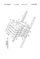
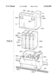
- FIG 1 is an exploded perspective view of a carriage and an ink tank unit for an ink jet printer according to a first embodiment of the invention
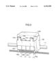
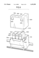
- FIG. 2 is a perspective view of the ink tank unit attached in the carriage according to the first embodiment
- FIG. 3 is an exploded view of a carriage and ink tank unit for an ink jet printer according to a second embodiment
- FIG. 4 is a perspective view of the ink tank unit of the second embodiment when it is attached in the carriage;
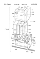
- FIG. 5 is an exploded perspective view of a carriage and ink tank unit for an ink jet printer according to a third embodiment
- FIG. 6 is an exploded view of ink tanks shortly after they have been attached into the carriage of the third embodiment
- FIG. 7 shows all of the ink tanks of the third embodiment attached in the carriage
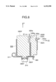
- FIG. 8 is a cross-sectional view taken along the lines XIII--XIII of FIG. 7;
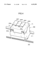
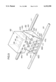
- FIG. 9 is an exploded perspective view of a carriage and ink tank unit for an ink jet printer according to a fourth embodiment.
- FIG. 10 is a perspective view of a relevant portion of a conventional ink jet printer.
- FIG. 1 is an exploded perspective view of a carriage and ink tank unit for an ink jet printer according to a first embodiment of the invention.
- FIG. 2 is a perspective view of the ink tank unit attached in the carriage.
- a carriage 152 is slidably supported on a carriage shaft 111 which extends through a support 152i of the carriage 152.
- the carriage 152 carries printheads 114 and ink tank unit 155 thereon and reciprocates along the guide rail 160 and carriage shaft 111.
- the carriage 152 includes a front wall 152c, a rear wall 152k, two opposite side walls 152b, and guide hooks 152g which slidably engage the guide rail 160.
- the front wall 152c is lower than the rear wall 152k.
- the carriage 152 further includes walls 152d by which the carriage 152 is partitioned into individual ink tank rooms.
- the ink tank rooms have ink entrances 156Y, 156M, 156C, and 156B formed in the bottoms thereof.
- Each wall 152d has a guide rib 152e which extends vertically along the wall 152 to facilitate insertion of an ink tank into a corresponding ink tank room.
- the guide ribs 152e are formed on the walls 152d such that they are at mutually different distances L1, L2, L3, and L4 from corresponding ends of the walls 152.
- the distances L1, L2, L3, and L4 are related by L1>L2>L3>L4.
- Each of the opposing side walls 152b is formed with a cutout 152f lower than the ink tanks so that the ink tanks can be easily taken out from the carriage 152.
- the front wall 152c has two projections 152m formed with latches 152h which engage the ink tank 155B to hold the ink tank 155B in place when the ink tank 155B is inserted into the
- the ink tank unit 155 includes four ink tanks 155Y, 155M, 155C, and 155B, which are aligned side by side from left to right in FIG. 1 and hold yellow ink, magenta ink, cyan ink, and black ink, respectively.
- the ink tanks 155Y, 155M, and 155C are of the same volume or capacity.
- the ink tank 155B is generally L-shaped, including a vertical portion P1 and a horizontal portion P2 which extends over the ink tanks of primary colors when attached into the carriage 152.
- the ink tank 155B has a larger volume than any one of the three other ink tanks, having a predetermined volume ratio to each of the three ink tanks 155Y, 155M, and 155C.
- the ink tanks are provided with ink exits 157Y, 157M, 157C, and 157B, respectively, which open and project downwardly.
- the ink exits include valves that are closed to provide a seal against the environment when the ink tanks 155Y, 155M, 155C, and 155B are not attached to the carriage.
- the ink tanks are formed with vertically extending grooves 155f in correspondence with the ribs 152e, the grooves being at mutually different distances L1, L2, L3, and L4 from corresponding ends of the ink tanks.
- the distances L1, L2, L3, and L4 are related by L1>L2>L3>L4.
- Each groove 155f fittingly engages a corresponding guide rib 156e to guide the ink tank into the carriage 152, thereby preventing inadvertent misplacement of the ink tanks in the carriage 152.
- the ink tanks 155Y, 155M, 155C are formed with stepped portions 155a at their top corners and the ink tank 155B is formed with projections 155g corresponding to the stepped portions 155a.
- the ink tank 155B also has two recesses 155h in its outer wall of the horizontal portion P2.
- the ink tank 155B is attached into the carriage 152 after the ink tanks 155Y, 155M, 155C, and 155B have been attached, the three projections 155g are received in the stepped portions 155a firmly holding the three other ink tanks.
- the latches 152h of the carriage 152 snap into the recesses 155h, holding the ink tank 155B in position in the carriage 152.
- all the ink tanks are securely held in place as shown in FIG. 2.
- the ink exits 157Y, 157M, 157C, and 157B fit into the ink entrances 156Y, 156M, 156C, and 156B, respectively, in a sealing relation, so that ink of each ink tank is supplied to a corresponding printhead, not shown.
- the projections 155g of the ink tank 155B push the three other ink tanks 155Y, 155M, and 155C downward so that the ink tank 155B securely holds the three other ink tanks in the carriage 152.
- tabs 152a above the latches 152h can be pulled toward the user.
- the projections 152m resiliently deform so that the latches 152h move out of engagement with the recesses 155h and the ink tank may be taken out with the hand.
- the two side walls 152b and the front and rear walls 152k and 152c may be omitted.
- the aforementioned construction makes the volume of the ink tank 155B about two to four times that of the other three ink tanks without the need for making the width of ink tanks 155Y, 155M, and 155C narrower. Further, the construction requires less frequent replacement of the ink tanks.
- FIG. 3 is an exploded view of a carriage and ink tank unit for an ink jet printer according to a second embodiment.
- FIG. 4 is a perspective view of the ink tank unit when it is attached in the carriage.
- the second embodiment will be described with respect to a portion that differs from the first embodiment.
- the overall size of a carriage 252 is substantially the same as the carriage 152 of the first embodiment.
- the carriage 252 is partitioned by walls 252d into individual rooms.
- the walls have vertically extending guide ribs 252e thereon.
- the guide ribs 252e are formed on the walls 252d such that they are at mutually different distances L1, L2, L3, and L4 from corresponding ends of the walls 252d.
- the distances L1, L2, L3, and L4 are related by L1>L2>L3>L4.
- Ink tanks 255Y, 255M, 255C, and 255B hold yellow ink, magenta ink, cyan ink, and black ink, respectively.
- a black ink tank 255B is generally L-shaped including a portion P3 and a portion P4. When attached into the carriage 252, the ink tank 255B extends in a lateral direction to cover the ink tanks of primary colors 255Y, 255M, and 255C.
- the height H2 and depth D2 of the ink tanks 255Y, 255M, and 255C and the height H1 and depth D1 of the ink tank 255B are related by D2>D1 and H1 ⁇ H2.
- the ink tank 255B has three lateral projections 255g.
- the ink tanks 255Y, 255M, and 255C have stepped portions 255a at their upper corners. All of the ink tanks 255Y, 255M, 255C, and 255B are formed with vertically extending guide grooves 255b in their outer wall surfaces at mutually different distances from corresponding ends of the outer walls, so that the guide ribs 252e slidably fit into the guide grooves 255b when the ink tanks are attached into the carriage. This construction prevents inadvertent misplacement of the ink tanks in the carriage.
- the guide grooves 255b are at mutually different distances L1, L2, L3, and L4 from corresponding ends of the ink tanks. The distances L1, L2, L3, and L4 are related by L1>L2>L3>L4.
- the projections 255g are received into the stepped portions 255a, the ink tank 255B firmly laterally holding the three ink tanks in place and the latches 252h of the carriage 252 snap into engagement with the recesses 255h in the ink tank 255B.
- the projections 255g of the ink tank 255B push the three other ink tanks downward so that the ink tank 255B securely holds the three other ink tanks in the carriage 252 as shown in FIG. 4.
- FIGS. 5-6 are exploded perspective view of an ink tank unit and a carriage according to a third embodiment.
- the third embodiment differs from the first and second embodiments in that ink tanks can be attached into and taken out from the carriage independently of each other.
- the carriage 352 is of the same construction as the carriage 252 of the second embodiment and therefore the description thereof is omitted.
- the ink tank units 355Y, 355M, 355C, and 355B are aligned in this order from left to right in FIG. 5.
- Four ink tanks 355Y, 355M, 355C, and 355B will be mainly described with respect to portions which are different from those of the second embodiment.
- the ink tank 355B includes a portion P5 and a portion P6 which communicate with each other and form a generally L-shape.
- the portion P5 has three recesses 355c in its one side surface and two recesses 355h in its other side surface.
- the upper portion of the portion P3 extends somewhat in a direction shown in FIG. 8.
- the ink tank 355Y, 355M, 355C each have an upwardly projecting resilient tab 355d which is formed with a latch 355g in its middle.
- the carriage 352 is slidably held on the carriage shaft 311.
- Each of walls 352d has a guide rib 352e which extends vertically along the wall 352d.
- the guide ribs 352e are formed on the walls 352d such that they are at mutually different distances L1, L2, L3, and L4 from corresponding ends of the walls 352d.
- the distances L1, L2, L3, and L4 are related by L1>L2>L3>L4.
- the guide ribs 352e engage grooves 355f formed in the ink tanks to facilitate insertion of an ink tank into a corresponding ink tank room.
- FIG. 6 is an exploded view of ink tanks 355Y, 355M, and 355C shortly after they have been attached into the carriage 352.
- the latches 352h of the carriage 352 snap into the recesses 355h in the ink tank 355B to firmly hold the ink tank 355B in place.
- the recesses 355c of the ink tank 355B push the three other ink tanks 355Y, 355M, and 355C downward so that the ink tank 355B securely holds the three other ink tanks in the carriage 352 as shown in FIG. 7.
- FIG. 7 illustrates all of the ink tanks which have been attached in the carriage.
- FIG. 8 is a cross-sectional view taken along the lines XIII--XIII of FIG. 7.
- the latches 355g of the ink tanks 355Y, 355M, and 355C snap into the recesses 355c in the ink tank 355B so that the ink tanks 355Y, 355M, and 355C are firmly held in the carriage 352.
- the ink tanks may be attached in the carriage in an arbitrary sequence.
- the ink tank 355B is held firmly by the latches 352h and the latches 355g of the ink tanks of primary colors 355Y, 355M, and 355C engage the recesses 355c to firmly hold the ink tanks of primary colors.
- the tabs 355a are pulled in a direction shown by arrow X1 and the ink tank 355Y is grasped by the hand and subsequently pulled in a direction shown by arrow Y.
- the tabs 355a are pulled in a direction shown by arrow X2 and the ink tank 355B is grasped by the hand and subsequently pulled in the direction shown by arrow Y.
- FIG. 9 is an exploded perspective view of a carriage and ink tank unit for an ink jet printer according to a fourth embodiment.
- the fourth embodiment is directed to a construction where a single black ink tank 485 of a large volume is provided for monochrome printing.
- the construction is the same as the conventional construction shown in FIG. 10 except for an additional black ink tank 485 and therefore description will be given only for the construction related to the black ink tank 485.
- the carriage 452 carries four printheads 414 and an ink tank unit 455 thereon.
- the carriage 452 is slidably supported on a carriage shaft 411 and guide rail 460 using guide latches 452g and reciprocated along the guide rail 460 and the carriage shaft 411.
- the carriage shaft 411 slidably extends through a support 452i and the guide latches 452g slide on the guide rail 460.
- the carriage includes two opposing triangular side walls 452j and a rear wall 452k between the two side walls 452j, and a bottom wall 452d.
- the bottom wall 452d is provided with ink entrances 456Y, 456M, 456C, and 456B and four printheads 414.
- each printhead 414 receives ink from a corresponding ink tank through a corresponding ink entrance.
- the carriage has four generally flat projections 452m rising from the bottom 452d at locations opposing the rear wall 452k. When the ink tank is attached into the carriage 452, each of the projection 452m is formed with a latch 452h which engages a corresponding ink tank to hold the tank in position.
- Color printers consume black ink more than any other colored ink.
- another black ink tank 485 is provided which holds substantially the same amount of ink as the total amount of ink of the three ink tanks of colored inks.
- FIG. 9 illustrates the black ink tank 485 just before it is attached into the carriage 452.
- Three caps 488-490 which are made of a resilient material and project downwardly from the bottom of the ink tank 485 at locations corresponding to the ink entrances 456Y, 456M, 456C, and 456B.
- the caps 488-490 are pressed against the ink entrances 456Y, 456M, and 456C to completely seal the ink entrances 456Y, 456M, and 456C against the environment.
- the ink exit 487 fits into the ink entrance 456B.
- the latches 452h on projections 452m snap into the corresponding recesses 485a to firmly hold the ink tank 485 in place.
- the user simply pulls tabs 452a of projections 452m toward the user so that the latches 452h disengage from the recesses 485a.
- the ink tank 485 is exposed beside the triangular walls and therefore the ink tank 485 can be grasped easily with fingers to take out the ink tank from the carriage 452.
- the ink exits 456Y, 456M, and 456C are firmly capped with the caps 488-490, there is no possibility of foreign materials of entering through the ink entrances while also preventing the ink from drying out.
- the ink tanks of yellow, magenta, and cyan inks, not shown, and the ink tank 485 can be selectively attached in the carriage 452, and therefore the color printing and the monochrome printing can be selectively performed. This feature can save the running cost of the ink jet printer.
- the aforementioned construction provides a large volume or capacity of the ink tank 485 as compared to the ink tanks of yellow, magenta, and cyan inks.
- volume ratio of the ink tank 485 to the ink tanks of primary colors can be increased without the need for decreasing the width of the ink tanks 475Y, 475M, and 475C.
Applications Claiming Priority (2)
| Application Number | Priority Date | Filing Date | Title |
|---|---|---|---|
| JP9028107A JPH10226086A (ja) | 1997-02-12 | 1997-02-12 | インクジェットプリンタ |
| JP9-028107 | 1997-02-12 |
Publications (1)
| Publication Number | Publication Date |
|---|---|
| US6152558A true US6152558A (en) | 2000-11-28 |
Family
ID=12239597
Family Applications (1)
| Application Number | Title | Priority Date | Filing Date |
|---|---|---|---|
| US09/020,419 Expired - Lifetime US6152558A (en) | 1997-02-12 | 1998-02-09 | Ink jet printer |
Country Status (2)
| Country | Link |
|---|---|
| US (1) | US6152558A (ja) |
| JP (1) | JPH10226086A (ja) |
Cited By (8)
| Publication number | Priority date | Publication date | Assignee | Title |
|---|---|---|---|---|
| US20080238958A1 (en) * | 2007-03-30 | 2008-10-02 | Seiko Epson Corporation | Carriage, recording apparatus, and liquid ejecting apparatus |
| US20080259143A1 (en) * | 2007-01-30 | 2008-10-23 | Brother Kogyo Kabushiki Kaisha | Ink Cartridges |
| EP2039521A1 (en) * | 2008-02-28 | 2009-03-25 | Brother Kogyo Kabushiki Kaisha | Ink cartridge |
| US20090097896A1 (en) * | 2007-10-15 | 2009-04-16 | William Michael Connors | Printhead Carrier Having Zero Clearance Bearing Arrangement |
| WO2010104500A3 (en) * | 2009-03-09 | 2011-08-11 | Hewlett-Packard Development Company, L.P. | Ink supply container |
| CN102615975A (zh) * | 2012-03-13 | 2012-08-01 | 新会江裕信息产业有限公司 | 一种打印机字车结构总成 |
| CN106313903A (zh) * | 2009-03-09 | 2017-01-11 | 惠普开发有限公司 | 墨液供应容器 |
| US20180015720A1 (en) * | 2016-07-15 | 2018-01-18 | Seiko Epson Corporation | Liquid ejecting apparatus |
Families Citing this family (1)
| Publication number | Priority date | Publication date | Assignee | Title |
|---|---|---|---|---|
| JP6131529B2 (ja) * | 2012-04-25 | 2017-05-24 | セイコーエプソン株式会社 | 流体噴射装置 |
Citations (7)
| Publication number | Priority date | Publication date | Assignee | Title |
|---|---|---|---|---|
| US5148194A (en) * | 1984-08-06 | 1992-09-15 | Canon Kabushiki Kaisha | Ink jet recording apparatus with engaging members for precisely positioning adjacent heads |
| EP0639462A2 (en) * | 1993-08-19 | 1995-02-22 | Canon Kabushiki Kaisha | Ink tank cartridge and ink-jet apparatus in which the ink tank cartridge is installed |
| US5408746A (en) * | 1993-04-30 | 1995-04-25 | Hewlett-Packard Company | Datum formation for improved alignment of multiple nozzle members in a printer |
| EP0674997A2 (en) * | 1994-03-30 | 1995-10-04 | Canon Kabushiki Kaisha | Ink jet recording apparatus and ink tank used for the ink jet recording apparatus |
| US5912689A (en) * | 1995-06-21 | 1999-06-15 | Canon Kabushiki Kaisha | Ink tank mounted on an ink jet apparatus |
| US6007191A (en) * | 1993-08-19 | 1999-12-28 | Fuji Xerox Co., Ltd. | Ink supply unit |
| US6012808A (en) * | 1992-07-24 | 2000-01-11 | Canon Kabushiki Kaisha | Ink container, ink and ink jet recording apparatus using ink container |
-
1997
- 1997-02-12 JP JP9028107A patent/JPH10226086A/ja not_active Withdrawn
-
1998
- 1998-02-09 US US09/020,419 patent/US6152558A/en not_active Expired - Lifetime
Patent Citations (7)
| Publication number | Priority date | Publication date | Assignee | Title |
|---|---|---|---|---|
| US5148194A (en) * | 1984-08-06 | 1992-09-15 | Canon Kabushiki Kaisha | Ink jet recording apparatus with engaging members for precisely positioning adjacent heads |
| US6012808A (en) * | 1992-07-24 | 2000-01-11 | Canon Kabushiki Kaisha | Ink container, ink and ink jet recording apparatus using ink container |
| US5408746A (en) * | 1993-04-30 | 1995-04-25 | Hewlett-Packard Company | Datum formation for improved alignment of multiple nozzle members in a printer |
| EP0639462A2 (en) * | 1993-08-19 | 1995-02-22 | Canon Kabushiki Kaisha | Ink tank cartridge and ink-jet apparatus in which the ink tank cartridge is installed |
| US6007191A (en) * | 1993-08-19 | 1999-12-28 | Fuji Xerox Co., Ltd. | Ink supply unit |
| EP0674997A2 (en) * | 1994-03-30 | 1995-10-04 | Canon Kabushiki Kaisha | Ink jet recording apparatus and ink tank used for the ink jet recording apparatus |
| US5912689A (en) * | 1995-06-21 | 1999-06-15 | Canon Kabushiki Kaisha | Ink tank mounted on an ink jet apparatus |
Cited By (17)
| Publication number | Priority date | Publication date | Assignee | Title |
|---|---|---|---|---|
| US20080259143A1 (en) * | 2007-01-30 | 2008-10-23 | Brother Kogyo Kabushiki Kaisha | Ink Cartridges |
| US8025379B2 (en) | 2007-01-30 | 2011-09-27 | Brother Kogyo Kabushiki Kaisha | Ink cartridges |
| US20080238958A1 (en) * | 2007-03-30 | 2008-10-02 | Seiko Epson Corporation | Carriage, recording apparatus, and liquid ejecting apparatus |
| US7766568B2 (en) | 2007-10-15 | 2010-08-03 | Lexmark International, Inc. | Printhead carrier having zero clearance bearing arrangement |
| US20090097896A1 (en) * | 2007-10-15 | 2009-04-16 | William Michael Connors | Printhead Carrier Having Zero Clearance Bearing Arrangement |
| EP2165838A3 (en) * | 2008-02-28 | 2010-04-28 | Brother Kogyo Kabushiki Kaisha | Ink cartridge |
| EP2179849A1 (en) * | 2008-02-28 | 2010-04-28 | Brother Kogyo Kabushiki Kaisha | Ink cartridge |
| EP2039521A1 (en) * | 2008-02-28 | 2009-03-25 | Brother Kogyo Kabushiki Kaisha | Ink cartridge |
| WO2010104500A3 (en) * | 2009-03-09 | 2011-08-11 | Hewlett-Packard Development Company, L.P. | Ink supply container |
| US20120001990A1 (en) * | 2009-03-09 | 2012-01-05 | Hewlett-Packard Development Company, L.P. | Ink supply container |
| CN102348557A (zh) * | 2009-03-09 | 2012-02-08 | 惠普开发有限公司 | 墨液供应容器 |
| US8657424B2 (en) * | 2009-03-09 | 2014-02-25 | Hewlett-Packard Development Company, L.P. | Ink supply container |
| CN106313903A (zh) * | 2009-03-09 | 2017-01-11 | 惠普开发有限公司 | 墨液供应容器 |
| CN102615975A (zh) * | 2012-03-13 | 2012-08-01 | 新会江裕信息产业有限公司 | 一种打印机字车结构总成 |
| US20180015720A1 (en) * | 2016-07-15 | 2018-01-18 | Seiko Epson Corporation | Liquid ejecting apparatus |
| CN107618268A (zh) * | 2016-07-15 | 2018-01-23 | 精工爱普生株式会社 | 液体喷射装置 |
| US10189256B2 (en) * | 2016-07-15 | 2019-01-29 | Seiko Epson Corporation | Liquid ejecting apparatus |
Also Published As
| Publication number | Publication date |
|---|---|
| JPH10226086A (ja) | 1998-08-25 |
Similar Documents
| Publication | Publication Date | Title |
|---|---|---|
| CA2130301C (en) | Ink tank cartridge and ink-jet apparatus installed the ink tank cartridge | |
| AU2001231257B2 (en) | Latch and handle arrangement for a replaceable ink container | |
| KR100731410B1 (ko) | 교환가능한 잉크 용기 및 그 조립 방법 | |
| US6488369B1 (en) | Ink container configured to establish reliable electrical and fluidic connections to a receiving station | |
| US6152558A (en) | Ink jet printer | |
| AU2001231257A1 (en) | Latch and handle arrangement for a replaceable ink container | |
| US10112405B2 (en) | Replaceable liquid supply having cut outs and latch | |
| JP2003054008A (ja) | 脱着式プリンタ部品のプリンタとの互換性を確立する分離可能なキー装置 | |
| US11865844B2 (en) | Liquid cartridge including first and second protrusions on top wall of housing | |
| WO2007117036A1 (ja) | 液体収容容器 | |
| CN207535498U (zh) | 墨容纳单元及具有其的喷墨打印机 | |
| US20110032312A1 (en) | Multi-color ink tank with features spaced by distances ensuring interface with printhead | |
| WO2017086440A1 (en) | Ink container and inkjet printer | |
| US6120128A (en) | Container for safekeeping ink cartridge | |
| US6827432B2 (en) | Replaceable ink container for an inkjet printing system | |
| CN205130643U (zh) | 墨容纳单元和喷墨打印机 | |
| KR20070097229A (ko) | 프린터용 잉크 카트리지 | |
| US11667127B2 (en) | Liquid cartridge including housing configured of base and cover in engagement with each other | |
| EP3960472B1 (en) | Liquid cartridge | |
| EP3960471B1 (en) | Liquid cartridge | |
| CN101959687B (zh) | 喷墨打印装置及其打印头组件 | |
| US20220371323A1 (en) | Inkjet printer | |
| EP3960473B1 (en) | Liquid cartridge | |
| CN205130644U (zh) | 墨容纳单元和喷墨打印机 | |
| CN110023090A (zh) | 打印流体盒与包括打印流体盒和打印流体消耗设备的系统 |
Legal Events
| Date | Code | Title | Description |
|---|---|---|---|
| AS | Assignment |
Owner name: OKI DATA CORPORATION, JAPAN Free format text: ASSIGNMENT OF ASSIGNORS INTEREST;ASSIGNORS:TOGASHI, SHIGEMI;SHIOBARA, TOSHIMASA;REEL/FRAME:008974/0885 Effective date: 19980123 |
|
| STCF | Information on status: patent grant |
Free format text: PATENTED CASE |
|
| FPAY | Fee payment |
Year of fee payment: 4 |
|
| FPAY | Fee payment |
Year of fee payment: 8 |
|
| FEPP | Fee payment procedure |
Free format text: PAYER NUMBER DE-ASSIGNED (ORIGINAL EVENT CODE: RMPN); ENTITY STATUS OF PATENT OWNER: LARGE ENTITY Free format text: PAYOR NUMBER ASSIGNED (ORIGINAL EVENT CODE: ASPN); ENTITY STATUS OF PATENT OWNER: LARGE ENTITY |
|
| FPAY | Fee payment |
Year of fee payment: 12 |