US6152231A - Wellhead drive brake system - Google Patents
Wellhead drive brake system Download PDFInfo
- Publication number
- US6152231A US6152231A US09/043,277 US4327798A US6152231A US 6152231 A US6152231 A US 6152231A US 4327798 A US4327798 A US 4327798A US 6152231 A US6152231 A US 6152231A
- Authority
- US
- United States
- Prior art keywords
- rod string
- fluid
- rotary member
- top end
- pump
- Prior art date
- Legal status (The legal status is an assumption and is not a legal conclusion. Google has not performed a legal analysis and makes no representation as to the accuracy of the status listed.)
- Expired - Lifetime
Links
- 239000012530 fluid Substances 0.000 claims abstract description 51
- 238000005086 pumping Methods 0.000 claims description 15
- 239000003921 oil Substances 0.000 description 3
- 239000003129 oil well Substances 0.000 description 2
- 239000003638 chemical reducing agent Substances 0.000 description 1
- 230000008878 coupling Effects 0.000 description 1
- 238000010168 coupling process Methods 0.000 description 1
- 238000005859 coupling reaction Methods 0.000 description 1
- 239000010779 crude oil Substances 0.000 description 1
- 238000007599 discharging Methods 0.000 description 1
- 238000006073 displacement reaction Methods 0.000 description 1
- 238000009434 installation Methods 0.000 description 1
- 230000004048 modification Effects 0.000 description 1
- 238000012986 modification Methods 0.000 description 1
- 230000000750 progressive effect Effects 0.000 description 1
- 239000004576 sand Substances 0.000 description 1
- XLYOFNOQVPJJNP-UHFFFAOYSA-N water Substances O XLYOFNOQVPJJNP-UHFFFAOYSA-N 0.000 description 1
Images
Classifications
-
- F—MECHANICAL ENGINEERING; LIGHTING; HEATING; WEAPONS; BLASTING
- F04—POSITIVE - DISPLACEMENT MACHINES FOR LIQUIDS; PUMPS FOR LIQUIDS OR ELASTIC FLUIDS
- F04C—ROTARY-PISTON, OR OSCILLATING-PISTON, POSITIVE-DISPLACEMENT MACHINES FOR LIQUIDS; ROTARY-PISTON, OR OSCILLATING-PISTON, POSITIVE-DISPLACEMENT PUMPS
- F04C14/00—Control of, monitoring of, or safety arrangements for, machines, pumps or pumping installations
- F04C14/28—Safety arrangements; Monitoring
-
- E—FIXED CONSTRUCTIONS
- E21—EARTH DRILLING; MINING
- E21B—EARTH DRILLING, e.g. DEEP DRILLING; OBTAINING OIL, GAS, WATER, SOLUBLE OR MELTABLE MATERIALS OR A SLURRY OF MINERALS FROM WELLS
- E21B43/00—Methods or apparatus for obtaining oil, gas, water, soluble or meltable materials or a slurry of minerals from wells
- E21B43/12—Methods or apparatus for controlling the flow of the obtained fluid to or in wells
- E21B43/121—Lifting well fluids
- E21B43/126—Adaptations of down-hole pump systems powered by drives outside the borehole, e.g. by a rotary or oscillating drive
-
- F—MECHANICAL ENGINEERING; LIGHTING; HEATING; WEAPONS; BLASTING
- F04—POSITIVE - DISPLACEMENT MACHINES FOR LIQUIDS; PUMPS FOR LIQUIDS OR ELASTIC FLUIDS
- F04C—ROTARY-PISTON, OR OSCILLATING-PISTON, POSITIVE-DISPLACEMENT MACHINES FOR LIQUIDS; ROTARY-PISTON, OR OSCILLATING-PISTON, POSITIVE-DISPLACEMENT PUMPS
- F04C11/00—Combinations of two or more machines or pumps, each being of rotary-piston or oscillating-piston type; Pumping installations
-
- F—MECHANICAL ENGINEERING; LIGHTING; HEATING; WEAPONS; BLASTING
- F04—POSITIVE - DISPLACEMENT MACHINES FOR LIQUIDS; PUMPS FOR LIQUIDS OR ELASTIC FLUIDS
- F04C—ROTARY-PISTON, OR OSCILLATING-PISTON, POSITIVE-DISPLACEMENT MACHINES FOR LIQUIDS; ROTARY-PISTON, OR OSCILLATING-PISTON, POSITIVE-DISPLACEMENT PUMPS
- F04C15/00—Component parts, details or accessories of machines, pumps or pumping installations, not provided for in groups F04C2/00 - F04C14/00
- F04C15/0057—Driving elements, brakes, couplings, transmission specially adapted for machines or pumps
- F04C15/0061—Means for transmitting movement from the prime mover to driven parts of the pump, e.g. clutches, couplings, transmissions
-
- F—MECHANICAL ENGINEERING; LIGHTING; HEATING; WEAPONS; BLASTING
- F05—INDEXING SCHEMES RELATING TO ENGINES OR PUMPS IN VARIOUS SUBCLASSES OF CLASSES F01-F04
- F05B—INDEXING SCHEME RELATING TO WIND, SPRING, WEIGHT, INERTIA OR LIKE MOTORS, TO MACHINES OR ENGINES FOR LIQUIDS COVERED BY SUBCLASSES F03B, F03D AND F03G
- F05B2270/00—Control
- F05B2270/10—Purpose of the control system
- F05B2270/109—Purpose of the control system to prolong engine life
- F05B2270/1097—Purpose of the control system to prolong engine life by preventing reverse rotation
Definitions
- This invention relates generally to the oil production industry, and has to do particularly with improving the safety of rotary downhole pumps, particularly upon shut down or power failure.
- the motor connected to the rod string through a reducer and a sheave and pulley arrangement, may reach reverse speeds exceeding safe limits. These speeds tend to damage the motor, and can even cause it to explode.
- one or both of the sheaves can reach speeds exceeding their limits.
- the projecting portion can bend and break, and the broken-off portion will then be flung away from the installation, due to centrifugal force.
- the rod string could uncouple, with the result that the rod string and the pump would be lost down the hole.
- this invention provides, for use with a pumping system in which a downhole pump has a rotor which is rotated by the bottom end of a rod string of which the top end is in turn rotated by torque energy derived from a prime mover, and in which twist energy is stored in the rod string during operation,
- a braking mechanism for avoiding a too sudden release of said twist energy in the rod string on shut down or power failure, the mechanism comprising:
- a rotary member mounted so that it rotates at a consistent speed ratio and direction with respect to the top end of the rod string
- an over-running clutch operatively associated with the fluid pump such that, when the top end of the rod string rotates in the direction corresponding to normal operating of the downhole pump, no pumping work is done by the fluid pump, but when the top end of the rod string rotates in the direction opposite that corresponding to normal operation of the downhole pump, the fluid pump does the work of pumping the fluid out of and then back to said reservoir against a resistance determined by the setting of the valve,
- This invention further provides a pumping system comprising:
- a downhole pump which includes a stator and a rotor
- a rod string having a top end and a bottom end, the bottom end being connected to, supporting and rotating said rotor
- a prime mover providing torque energy for rotating said top end, whereby twist energy is stored in the rod string during operation
- a braking mechanism for avoiding a too sudden release of said twist energy in the rod string on shut down or power failure, the mechanism including:
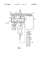
- FIG. 1 is a side elevational view of a braking mechanism in accordance with the present invention.
- FIG. 2 is an end view of the braking mechanism, seen in the direction of the arrow 2 in FIG. 1.
- FIG. 1 is a somewhat schematic representation of the major components of the braking system to be described herein.
- a prime mover is constituted by a motor 10 which has an upstanding shaft 12 carrying a sheave 14.
- a braking mechanism including a rotary member 16, carrying at the top a sheave 18 in alignment with the sheave 14.
- the rotary member 16 is an elongate shaft parallel with the shaft 12, and extends through the interior of a reservoir 20 which is open to the atmosphere at the top 22 and includes of two side walls 24 (only one visible in FIG. 1) and two end walls 26.
- a bottom wall 28 is also a part of the reservoir 20, and the shaft 16 passes through the bottom wall 28, but is sealed thereagainst to prevent leakage.
- a main drive shaft 30 which is supported for rotation by a seal housing 32.
- the main drive shaft 30 is adapted to support the top end of a rod string 34 which extends down the well.
- the main drive shaft 30 passes through the bottom wall 28 of the reservoir 20, and is appropriately sealed to prevent leakage.
- the reservoir 20 is filled to about 2/3rds with hydraulic fluid 36.
- each of the shafts 16 and 30 carries a pinion gear, the two gears meshing in such a way that the ratio of rotation between the shafts 16 and 30 remains constant (with the shafts rotating in opposite directions).
- Another variant involves the provision of a sprocket on each of the shafts 16 and 30, along with a chain engaging both sprockets. In the second case, the shafts 16 and 30 would rotate in the same direction.
- FIGS. 1 and 2 Attention is now directed to both FIGS. 1 and 2, for a more detailed description of the braking mechanism.
- a hydraulic pump 40 communicates on the suction side with an intake manifold 42, and on the discharge side with a discharge manifold 44.
- a flow control valve 46 Located in the discharge manifold 44 is a flow control valve 46 which can be manually adjusted in order to determine the resistance to flow through the discharge manifold 44.
- Both the manifold 42 and 44 communicate with the interior of the reservoir 20, through sealed openings.
- FIG. 2 shows schematically that the shaft 16 is connected to an over-running clutch 48 which is in turn connected through flexible couplings 50 to the input power shaft 52 of the pump 40.
- the over-running clutch 48 is also called a "sprague” clutch, which transmits power only in one direction of rotation, but “slips” when it rotates in the opposite direction.
- the over-running clutch sends power to the pump 40 only when the top end of the rod string 34 rotates in the direction opposite that corresponding to normal operation, as it attempts to do upon power failure or shut down.
- the clutch slips and fails to run the fluid pump 40.
- the rod string 34 will attempt to spin backwards, as the stored torque energy is released, This will cause rotation of the shaft 30, which in turn will rotate the shaft 16 through the meshing gears or the chain-locked sprockets.
- the rotational direction of the shaft 16 is such as to power the hydraulic pump 40 through the over-running clutch 48, thus causing oil to be drawn from the reservoir 20 through the intake manifold 42, and discharging it through the flow control valve 46 and into the discharge manifold 44.
- the flow control valve 46 is selected such that, when substantially fully opened, the rod string 34 will be allowed to spin back at a relatively slow rate of rotation.
- oil from the reservoir 20 is continuously pumped in a closed loop by the pump 40, the closed loop containing an adjustable restriction in the form of the flow control valve 46.
- the bottom end 33 of the casing of a drilled well contains the stator 62 and the rotor 64 of a downhole, positive displacement rotary pump and the bottom end 65 of the rod string 34.
Applications Claiming Priority (1)
| Application Number | Priority Date | Filing Date | Title |
|---|---|---|---|
| PCT/CA1995/000520 WO1997010437A1 (en) | 1995-09-14 | 1995-09-14 | Wellhead drive brake system |
Publications (1)
| Publication Number | Publication Date |
|---|---|
| US6152231A true US6152231A (en) | 2000-11-28 |
Family
ID=4173107
Family Applications (1)
| Application Number | Title | Priority Date | Filing Date |
|---|---|---|---|
| US09/043,277 Expired - Lifetime US6152231A (en) | 1995-09-14 | 1995-09-14 | Wellhead drive brake system |
Country Status (9)
| Country | Link |
|---|---|
| US (1) | US6152231A (hu) |
| AU (1) | AU3467395A (hu) |
| BR (1) | BR9510639A (hu) |
| CA (1) | CA2232175C (hu) |
| DE (1) | DE19581945B4 (hu) |
| HU (1) | HU219961B (hu) |
| NO (1) | NO323270B1 (hu) |
| RO (1) | RO117558B1 (hu) |
| WO (1) | WO1997010437A1 (hu) |
Cited By (11)
| Publication number | Priority date | Publication date | Assignee | Title |
|---|---|---|---|---|
| US6419472B2 (en) * | 2000-03-08 | 2002-07-16 | A. Friedr. Flender Ag | Gear unit for a deep-borehole pump |
| EP1245831A3 (en) * | 2001-03-30 | 2002-12-04 | Eaton Corporation | Pump assembly |
| US20050163640A1 (en) * | 2004-01-23 | 2005-07-28 | Kudu Industries Inc. | Rotary drivehead for downhole apparatus |
| US20080060819A1 (en) * | 2006-09-08 | 2008-03-13 | National Oilwell Varco, L.P. | Systems and methods to retard rod string backspin |
| US20080135358A1 (en) * | 2006-12-06 | 2008-06-12 | Weatherford Industria E Comercio Ltda | Remote control for braking system of progressive cavity pump |
| US20080142209A1 (en) * | 2006-12-15 | 2008-06-19 | Weatherford Industria E Comercio Ltda. | Auxiliary braking device for wellhead having progressive cavity pump |
| US20130045116A1 (en) * | 2011-08-16 | 2013-02-21 | Yi Wang | Beamless Mechanic-reversing Long Stroke Pumping Unit |
| US8662186B2 (en) | 2011-03-15 | 2014-03-04 | Weatherford/Lamb, Inc. | Downhole backspin retarder for progressive cavity pump |
| US9181996B2 (en) | 2012-08-29 | 2015-11-10 | Titus Tools Inc. | Device for reducing rod string backspin in progressive cavity pump |
| US20150362035A1 (en) * | 2014-06-17 | 2015-12-17 | Yen-Hong Wong | Hydraulic auxiliary brake device of motor used for oil production |
| US10968718B2 (en) | 2017-05-18 | 2021-04-06 | Pcm Canada Inc. | Seal housing with flange collar, floating bushing, seal compressor, floating polished rod, and independent fluid injection to stacked dynamic seals, and related apparatuses and methods of use |
Families Citing this family (4)
| Publication number | Priority date | Publication date | Assignee | Title |
|---|---|---|---|---|
| US6241016B1 (en) | 1998-04-03 | 2001-06-05 | R & M Energy Systems | Drive head assembly |
| JP2001227461A (ja) | 2000-02-14 | 2001-08-24 | Matsushita Electric Ind Co Ltd | リニア圧縮機 |
| CA2311214A1 (en) * | 2000-06-09 | 2001-12-09 | Eduard Grenke | Pump brake system with interchangeable drive force |
| CN116025271B (zh) * | 2023-03-30 | 2023-06-06 | 山东省地质矿产勘查开发局八〇一水文地质工程地质大队(山东省地矿工程勘察院) | 一种地质勘探用土壤钻孔设备 |
Citations (10)
| Publication number | Priority date | Publication date | Assignee | Title |
|---|---|---|---|---|
| US4475872A (en) * | 1982-09-28 | 1984-10-09 | Robbins & Myers, Inc. | Water pump and gear box therefor |
| WO1988007126A1 (en) * | 1987-03-16 | 1988-09-22 | Superior Gearbox Company | Drive assembly with overspeed brake |
| US4797075A (en) * | 1987-04-09 | 1989-01-10 | Hughes Tool Company | Overspeed protective gear box for a well pump |
| GB2210931A (en) * | 1987-10-14 | 1989-06-21 | Tokyo Buhin Kogyo Co Ltd | Engine braking system |
| US4927333A (en) * | 1988-01-22 | 1990-05-22 | Toyota Jidosha Kabushiki Kaisha | Fluid pump |
| DE3907053A1 (de) * | 1989-03-04 | 1990-09-06 | Walter Arndt | Oelhydraulische dauerbremse zum abbremsen von fahrzeugen |
| US4993276A (en) * | 1987-03-13 | 1991-02-19 | Superior Gear Box Company | Drive assembly with overspeed brake |
| US4997346A (en) * | 1990-04-12 | 1991-03-05 | Atlantic Richfield Company | Well pumping systems |
| US5251696A (en) * | 1992-04-06 | 1993-10-12 | Boone James R | Method and apparatus for variable speed control of oil well pumping units |
| US5358036A (en) * | 1992-07-16 | 1994-10-25 | Mills Robert A R | Safety disc brake assembly |
Family Cites Families (1)
| Publication number | Priority date | Publication date | Assignee | Title |
|---|---|---|---|---|
| DE534429C (de) * | 1931-09-26 | Maschf Augsburg Nuernberg Ag | Einrichtung zur Regelung der Geschwindigkeit der getriebenen Welle eines Differential-Getriebes mittels hydraulischen Bremsreglers |
-
1995
- 1995-09-14 RO RO98-00728A patent/RO117558B1/ro unknown
- 1995-09-14 DE DE19581945T patent/DE19581945B4/de not_active Expired - Lifetime
- 1995-09-14 US US09/043,277 patent/US6152231A/en not_active Expired - Lifetime
- 1995-09-14 WO PCT/CA1995/000520 patent/WO1997010437A1/en active Application Filing
- 1995-09-14 BR BR9510639A patent/BR9510639A/pt not_active IP Right Cessation
- 1995-09-14 HU HU9900765A patent/HU219961B/hu unknown
- 1995-09-14 AU AU34673/95A patent/AU3467395A/en not_active Abandoned
- 1995-09-14 CA CA002232175A patent/CA2232175C/en not_active Expired - Lifetime
-
1998
- 1998-03-13 NO NO19981134A patent/NO323270B1/no not_active IP Right Cessation
Patent Citations (10)
| Publication number | Priority date | Publication date | Assignee | Title |
|---|---|---|---|---|
| US4475872A (en) * | 1982-09-28 | 1984-10-09 | Robbins & Myers, Inc. | Water pump and gear box therefor |
| US4993276A (en) * | 1987-03-13 | 1991-02-19 | Superior Gear Box Company | Drive assembly with overspeed brake |
| WO1988007126A1 (en) * | 1987-03-16 | 1988-09-22 | Superior Gearbox Company | Drive assembly with overspeed brake |
| US4797075A (en) * | 1987-04-09 | 1989-01-10 | Hughes Tool Company | Overspeed protective gear box for a well pump |
| GB2210931A (en) * | 1987-10-14 | 1989-06-21 | Tokyo Buhin Kogyo Co Ltd | Engine braking system |
| US4927333A (en) * | 1988-01-22 | 1990-05-22 | Toyota Jidosha Kabushiki Kaisha | Fluid pump |
| DE3907053A1 (de) * | 1989-03-04 | 1990-09-06 | Walter Arndt | Oelhydraulische dauerbremse zum abbremsen von fahrzeugen |
| US4997346A (en) * | 1990-04-12 | 1991-03-05 | Atlantic Richfield Company | Well pumping systems |
| US5251696A (en) * | 1992-04-06 | 1993-10-12 | Boone James R | Method and apparatus for variable speed control of oil well pumping units |
| US5358036A (en) * | 1992-07-16 | 1994-10-25 | Mills Robert A R | Safety disc brake assembly |
Cited By (22)
| Publication number | Priority date | Publication date | Assignee | Title |
|---|---|---|---|---|
| US6419472B2 (en) * | 2000-03-08 | 2002-07-16 | A. Friedr. Flender Ag | Gear unit for a deep-borehole pump |
| EP1245831A3 (en) * | 2001-03-30 | 2002-12-04 | Eaton Corporation | Pump assembly |
| US6572339B2 (en) | 2001-03-30 | 2003-06-03 | Eaton Corporation | Positive displacement fluid pump having improved fill characteristics |
| US7530800B2 (en) | 2004-01-23 | 2009-05-12 | Kudu Industries Inc. | Rotary drivehead for downhole apparatus |
| US20050163640A1 (en) * | 2004-01-23 | 2005-07-28 | Kudu Industries Inc. | Rotary drivehead for downhole apparatus |
| US20080060819A1 (en) * | 2006-09-08 | 2008-03-13 | National Oilwell Varco, L.P. | Systems and methods to retard rod string backspin |
| US8132618B2 (en) * | 2006-09-08 | 2012-03-13 | National Oilwell Varco, L.P. | Systems for retarding rod string backspin |
| US20080135358A1 (en) * | 2006-12-06 | 2008-06-12 | Weatherford Industria E Comercio Ltda | Remote control for braking system of progressive cavity pump |
| US20140138193A1 (en) * | 2006-12-06 | 2014-05-22 | Weatherford Industria E Comercio Ltda | Remote control for braking system of progressive cavity pump |
| US8955650B2 (en) * | 2006-12-06 | 2015-02-17 | Weatherford Industria E Comercio Ltda | Remote control for braking system of progressive cavity pump |
| US8550218B2 (en) * | 2006-12-06 | 2013-10-08 | Weatherford Industria E Comecio Ltda. | Remote control for braking system of progressive cavity pump |
| US20100322788A1 (en) * | 2006-12-15 | 2010-12-23 | Weatherford Industria E Comercio Ltda. | Auxiliary braking device for wellhead having progressive cavity pump |
| US20080142209A1 (en) * | 2006-12-15 | 2008-06-19 | Weatherford Industria E Comercio Ltda. | Auxiliary braking device for wellhead having progressive cavity pump |
| US8491278B2 (en) * | 2006-12-15 | 2013-07-23 | Weatherford Industria E Comecio Ltda. | Auxiliary braking device for wellhead having progressive cavity pump |
| US7806665B2 (en) * | 2006-12-15 | 2010-10-05 | Weatherford Industria E Comercio Ltda. | Auxiliary braking device for wellhead having progressive cavity pump |
| US8662186B2 (en) | 2011-03-15 | 2014-03-04 | Weatherford/Lamb, Inc. | Downhole backspin retarder for progressive cavity pump |
| US8955582B2 (en) * | 2011-08-16 | 2015-02-17 | Yi Wang | Beamless mechanic-reversing long stroke pumping unit |
| US20130045116A1 (en) * | 2011-08-16 | 2013-02-21 | Yi Wang | Beamless Mechanic-reversing Long Stroke Pumping Unit |
| US9181996B2 (en) | 2012-08-29 | 2015-11-10 | Titus Tools Inc. | Device for reducing rod string backspin in progressive cavity pump |
| US20150362035A1 (en) * | 2014-06-17 | 2015-12-17 | Yen-Hong Wong | Hydraulic auxiliary brake device of motor used for oil production |
| US9441683B2 (en) * | 2014-06-17 | 2016-09-13 | Yen-Hong Wong | Hydraulic auxiliary brake device of motor used for oil production |
| US10968718B2 (en) | 2017-05-18 | 2021-04-06 | Pcm Canada Inc. | Seal housing with flange collar, floating bushing, seal compressor, floating polished rod, and independent fluid injection to stacked dynamic seals, and related apparatuses and methods of use |
Also Published As
| Publication number | Publication date |
|---|---|
| DE19581945B4 (de) | 2005-03-17 |
| NO323270B1 (no) | 2007-02-19 |
| AU3467395A (en) | 1997-04-01 |
| CA2232175C (en) | 2008-11-18 |
| WO1997010437A1 (en) | 1997-03-20 |
| BR9510639A (pt) | 1999-01-12 |
| RO117558B1 (ro) | 2002-04-30 |
| DE19581945T1 (de) | 1998-12-03 |
| NO981134D0 (no) | 1998-03-13 |
| CA2232175A1 (en) | 1997-03-20 |
| HUT78067A (hu) | 1999-07-28 |
| NO981134L (no) | 1998-05-14 |
| HU219961B (hu) | 2001-10-28 |
Similar Documents
| Publication | Publication Date | Title |
|---|---|---|
| US6152231A (en) | Wellhead drive brake system | |
| US7806665B2 (en) | Auxiliary braking device for wellhead having progressive cavity pump | |
| US5358036A (en) | Safety disc brake assembly | |
| EP0840835B1 (en) | Improvements in deep well pumping apparatus | |
| CA2234920C (en) | Safety coupling for rotary pump | |
| US6202762B1 (en) | Flow restrictor valve for a downhole drilling assembly | |
| US5960886A (en) | Deep well pumping apparatus | |
| CA2187578C (en) | Pump drive head | |
| US20070253843A1 (en) | Hydraulically driven oil recovery system | |
| CA2900174A1 (en) | Fluid coupling drive system for a drill rig air compressor | |
| US3964558A (en) | Fluid actuated downhole drilling device | |
| CA2347942C (en) | Rotary shaft brake | |
| US5749416A (en) | Downhole pump drive head assembly | |
| CA2550066C (en) | Improved wellhead drive braking mechanism | |
| US6241016B1 (en) | Drive head assembly | |
| CA2239641C (en) | Continuous running gear pump brake system | |
| GB2299849A (en) | Downhole pump drive head assembly with hydrodynamic retarder | |
| WO2001094790A1 (en) | Transmission for deep well pump | |
| RU2159359C2 (ru) | Тормозной механизм для нагнетательной системы, нагнетательная система и способ работы нагнетательной системы | |
| CA2282231C (en) | Modular downhole multiphase pump | |
| MXPA98001983A (en) | Drive brake system for p head | |
| CN2644662Y (zh) | 液压驱动捞砂滚筒装置 | |
| CN1200791A (zh) | 井口驱动器的制动系统 | |
| CA2805584A1 (en) | Wellhead drive brake system | |
| RU2088737C1 (ru) | Турборедуктор |
Legal Events
| Date | Code | Title | Description |
|---|---|---|---|
| STCF | Information on status: patent grant |
Free format text: PATENTED CASE |
|
| FEPP | Fee payment procedure |
Free format text: PAYOR NUMBER ASSIGNED (ORIGINAL EVENT CODE: ASPN); ENTITY STATUS OF PATENT OWNER: LARGE ENTITY |
|
| FPAY | Fee payment |
Year of fee payment: 4 |
|
| FPAY | Fee payment |
Year of fee payment: 8 |
|
| AS | Assignment |
Owner name: GRENCO ENERGY SERVICES INC., CANADA Free format text: ASSIGNMENT OF ASSIGNORS INTEREST;ASSIGNOR:GRENCO INDUSTRIES LTD.;REEL/FRAME:025192/0576 Effective date: 20101005 Owner name: GRENCO INDUSTRIES LTD., CANADA Free format text: ASSIGNMENT OF ASSIGNORS INTEREST;ASSIGNOR:GRENKE, EDWARD, MR.;REEL/FRAME:025192/0570 Effective date: 20100603 |
|
| FPAY | Fee payment |
Year of fee payment: 12 |