US6152084A - Viscous fluid type heat generator filled with regulated amount of viscous fluid - Google Patents
Viscous fluid type heat generator filled with regulated amount of viscous fluid Download PDFInfo
- Publication number
- US6152084A US6152084A US08/876,076 US87607697A US6152084A US 6152084 A US6152084 A US 6152084A US 87607697 A US87607697 A US 87607697A US 6152084 A US6152084 A US 6152084A
- Authority
- US
- United States
- Prior art keywords
- fluid
- viscous fluid
- heat
- chamber
- containing chamber
- Prior art date
- Legal status (The legal status is an assumption and is not a legal conclusion. Google has not performed a legal analysis and makes no representation as to the accuracy of the status listed.)
- Expired - Fee Related
Links
- 239000012530 fluid Substances 0.000 title claims abstract description 206
- 230000001105 regulatory effect Effects 0.000 title 1
- 238000007789 sealing Methods 0.000 claims abstract description 29
- 230000009471 action Effects 0.000 claims abstract description 11
- 238000010008 shearing Methods 0.000 claims abstract description 11
- 239000007789 gas Substances 0.000 claims description 14
- 230000001590 oxidative effect Effects 0.000 claims description 9
- XKRFYHLGVUSROY-UHFFFAOYSA-N Argon Chemical compound [Ar] XKRFYHLGVUSROY-UHFFFAOYSA-N 0.000 claims description 6
- IJGRMHOSHXDMSA-UHFFFAOYSA-N Atomic nitrogen Chemical compound N#N IJGRMHOSHXDMSA-UHFFFAOYSA-N 0.000 claims description 6
- CURLTUGMZLYLDI-UHFFFAOYSA-N Carbon dioxide Chemical compound O=C=O CURLTUGMZLYLDI-UHFFFAOYSA-N 0.000 claims description 6
- 229910052786 argon Inorganic materials 0.000 claims description 3
- 239000001569 carbon dioxide Substances 0.000 claims description 3
- 229910002092 carbon dioxide Inorganic materials 0.000 claims description 3
- 239000001307 helium Substances 0.000 claims description 3
- 229910052734 helium Inorganic materials 0.000 claims description 3
- SWQJXJOGLNCZEY-UHFFFAOYSA-N helium atom Chemical compound [He] SWQJXJOGLNCZEY-UHFFFAOYSA-N 0.000 claims description 3
- 229910052754 neon Inorganic materials 0.000 claims description 3
- GKAOGPIIYCISHV-UHFFFAOYSA-N neon atom Chemical compound [Ne] GKAOGPIIYCISHV-UHFFFAOYSA-N 0.000 claims description 3
- 229910052757 nitrogen Inorganic materials 0.000 claims description 2
- 238000000034 method Methods 0.000 claims 7
- 238000010438 heat treatment Methods 0.000 description 18
- 239000007788 liquid Substances 0.000 description 16
- 229920002545 silicone oil Polymers 0.000 description 12
- 230000008878 coupling Effects 0.000 description 6
- 238000010168 coupling process Methods 0.000 description 6
- 238000005859 coupling reaction Methods 0.000 description 6
- 230000020169 heat generation Effects 0.000 description 5
- 230000005540 biological transmission Effects 0.000 description 2
- 238000004519 manufacturing process Methods 0.000 description 2
- 238000005259 measurement Methods 0.000 description 2
- 230000000704 physical effect Effects 0.000 description 2
- 239000000126 substance Substances 0.000 description 2
- 238000005299 abrasion Methods 0.000 description 1
- 230000015556 catabolic process Effects 0.000 description 1
- 239000000498 cooling water Substances 0.000 description 1
- 230000007547 defect Effects 0.000 description 1
- 238000006731 degradation reaction Methods 0.000 description 1
- 229910001873 dinitrogen Inorganic materials 0.000 description 1
- 230000001747 exhibiting effect Effects 0.000 description 1
- 230000004048 modification Effects 0.000 description 1
- 238000012986 modification Methods 0.000 description 1
- JCXJVPUVTGWSNB-UHFFFAOYSA-N nitrogen dioxide Inorganic materials O=[N]=O JCXJVPUVTGWSNB-UHFFFAOYSA-N 0.000 description 1
- 230000004044 response Effects 0.000 description 1
- 230000000717 retained effect Effects 0.000 description 1
Images

Classifications
-
- F—MECHANICAL ENGINEERING; LIGHTING; HEATING; WEAPONS; BLASTING
- F24—HEATING; RANGES; VENTILATING
- F24V—COLLECTION, PRODUCTION OR USE OF HEAT NOT OTHERWISE PROVIDED FOR
- F24V40/00—Production or use of heat resulting from internal friction of moving fluids or from friction between fluids and moving bodies
Definitions
- the present invention relates generally to a viscous fluid type heat generator in which a viscous fluid is filled in a predetermined fluid containing chamber defined within a housing assembly and is subjected to a repeated shearing action by the rotation of a rotor element so as to generate heat which is in turn transmitted to a circulating heat exchanging fluid in a heat receiving chamber.
- the heat is carried by the heat exchanging fluid to a desired heated area, such as a passenger compartment in an automobile.
- the present invention relates to a viscous fluid type heat generator in which the predetermined fluid containing chamber of the housing assembly is filled with a viscous fluid at filling rate suitable for generating heat of which the temperature is enough to be used with a heating system, while preventing a damage to an oil sealing device incorporated in the viscous fluid type heat generator.
- the supplementary heating device has a drive shaft operationally connected to and driven by a motor vehicle engine.
- the drive shaft is rotatably supported in a housing assembly which houses a rotor element drivingly connected to an inner end of the drive shaft.
- the housing assembly defines a heating chamber therein in which a predetermined amount of viscous fluid such as silicone oil is filled so that the viscous fluid is retained in spaces provided between the inner walls of the heat generating chamber and the outer surface of the rotor element.
- the filling rate of the viscous fluid for the heating chamber is generally set, for example, at higher than 80%, and the heating chamber is hermetically sealed by an oil seal element or a shaft seal element arranged within the heating chamber around the drive shaft so as to prevent leakage of the viscous fluid from the heating chamber.
- a fluid filling rate of 80% or more is based on the fact that the conventional viscous coupling device employing the same heat generating principle as the viscous fluid type heat generator has satisfactorily applied this filling rate.
- the viscous oil is used as a working medium, and an increase in the volume of the working medium due to frictional heat generation of the working medium is utilized for providing an adjustable fluid coupling between two clutch plates in order to transmit an adjusted torque from the input of the coupling device to the output thereof.
- the filling rate of the viscous fluid must be designed and set at a value as high as possible.
- the inner pressure within the heat generating chamber may excessively increase beyond a predetermined durable pressure (the maximum permissible pressure) for the oil seal, due to a difference in the thermal expansion coefficients of the viscous fluid and the air. As a result, damage to the oil seal and leakage of the viscous fluid from the heat generating chamber might occur.
- An object of the present invention is, therefore, to provide a viscous fluid type heat generator capable of exhibiting good operating reliability for a long operational life causing neither damage to an oil sealing device incorporated therein nor leakage of viscous fluid from a heat generating chamber thereof.
- Another object of the present invention is to provide an improved viscous fluid type heat generator having a sufficient and reliable heat generating performance without the addition of structural elements which may cause an increase in the manufacturing cost of the heat generator.
- a viscous fluid type heat generator which comprises:
- a housing assembly defining therein a fluid containing chamber for containing viscous fluid and a heat receiving chamber for permitting heat exchanging fluid to flow therethrough;
- a drive shaft rotatably supported by the housing assembly and rotationally driven by an external drive source, the drive shaft including a part thereof extending into the housing assembly;
- a rotor element mounted on the part of the drive shaft to be rotated in the fluid containing chamber, the rotation of the rotor element applying a shearing action to the viscous fluid to generate heat;
- a heat transmitting element arranged between the fluid containing chamber and the heat receiving chamber to transmit heat from the viscous fluid to the heat exchanging fluid
- a sealing element arranged around the drive shaft at a position adjacent to the fluid containing chamber to prevent the viscous fluid from leaking from the fluid containing chamber;
- the viscous fluid is filled in the fluid containing chamber at a predetermined volumetric filling rate selected from a range between 50% and 70% with respect to an entire volume of the fluid containing chamber.
- the fluid containing chamber includes a heat generating chamber in which the rotor element and the part of the drive shaft are located, the heat generating chamber being fluid-tightly sealed by the sealing element arranged adjacent to the part of the drive shaft, so that leakage of the viscous fluid over the outer circumference of the drive shaft is prevented. Since the sealing element is protected against breakage or abrasion by the specific arrangement of the filling rate of the viscous fluid into the fluid containing chamber of the heat generator, the operational life of the viscous fluid type heat generator can surely be long.
- the rest of volume of the fluid containing chamber of the viscous fluid type heat generator except for the volume filled with the viscous fluid is preferably filled with non-oxidizing gas.
- the filling of the non-oxidizing gas into the fluid containing chamber permits the air to be purged from the fluid containing chamber, and accordingly, the viscous fluid can be prevented from being oxidized.
- the chemical and physical properties of the viscous fluid are maintained unchanged for a long operational life of the heat generator. Therefore, a stable heat generating performance of the viscous fluid type heat generator can be maintained during the operational life of the heat generator.
- the non-oxidizing gas can be one of nitrogen gas, carbon dioxide, and a rare gas including helium (He) gas, neon (Ne) gas, and argon (Ar) gas.
- the content in the fluid containing chamber i.e., the viscous fluid and the non-oxidizing gas cannot be thermally expanded to have a pressure which is high above a limit of pressure that the sealing element incorporated in the viscous fluid type heat generator can physically endure.
- the sealing element is constantly subjected to an allowable pressure, and therefore, the mechanical durability of the sealing element can be maintained for a long operation life.
- the thermal expansion of the viscous fluid and the gaseous content of the fluid containing chamber causes an increase in the inner pressure within the fluid containing chamber to a high pressure level that the sealing element of the heat generator cannot endure.
- a defect may occur in that hermetic sealing of the fluid containing chamber is broken permitting the viscous fluid to leak from the fluid containing chamber.
- the filling rate of the viscous fluid into the fluid containing chamber is less than 50%, the amount of the viscous fluid subjected to the shearing action applied by the rotating rotor element within the fluid containing chamber is insufficient for generating heat to be supplied to the motor vehicle heating system, and accordingly, the heat generating performance of the viscous fluid type heat generator is low.
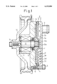
- FIG. 1 is a cross-sectional view of a viscous fluid type heat generator according to a first embodiment of the present invention
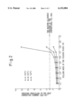
- FIG. 2 is a graphical view indicating a relationship between the filling rate of viscous fluid and inner pressure prevailing in the fluid containing chamber;
- FIG. 3 is a cross-sectional view of a viscous fluid type heat generator according to a second embodiment of the present invention.
- a viscous fluid type heat generator includes a housing assembly which is formed by a front housing 1, a separating plate 2, a rear housing body 3, and a sealing gasket 4.
- the front housing 1, the separating plate 2, the rear housing body 3, and the sealing gasket 4 are arranged to be juxtaposed in relation to one another, and combined together by a plurality of long screw bolts 5 (only one screw bolt 5 is shown in FIG. 1).
- the separating plate 2 and the rear housing body 3 form a rear housing 6 having a liquid inlet port 9 and a liquid outlet port (not shown in FIG. 1 but arranged in a similar manner to the liquid inlet 9).
- the front housing 1 is provided with an inner face which has a large recess formed therein so as to face a front end face of the separating plate 2 and to define a heat generating chamber 7.
- a rear end face of the separating plate 2 and an inner wall face of the rear housing body 3 define therebetween a heat receiving chamber 8 arranged adjacent to the heat generating chamber 7.
- the separating plate 2 isolates the heat receiving chamber 8 from the heat generating chamber 7, and acts as a heat transmitting member between the chambers 7 and 8.
- the heat receiving chamber 8 receives a heat exchanging liquid through the liquid inlet port 9, and delivers the liquid from the outlet port toward an external heating system such as a motor vehicle heating system.
- the heat exchanging liquid circulates through the heat receiving chamber 8 of the heat generator and the external motor vehicle heating system.
- the separating plate 2 is centrally provided with a columnar protrusion 2a projecting rearwardly from the separating plate toward the inner end face of the rear housing body 3.
- the rear end face of the separating plate 2 is provided with a radial wall portion 2b formed so as to extend radially from a part of the outer surface of the columnar protrusion 2a.
- the rear end face of the separating plate 2 is further provided with a plurality of fins 2c through 2f extending circumferentially from a position adjacent to the inlet port 9 toward a position adjacent to the outlet port.
- the columnar portion 2a, the radial wall portion 2b, and the plurality of fins 2c through 2f are kept in contact with the inner end face of the rear housing body 3 so as to form flow passageways for the heat exchanging liquid within the heat receiving chamber 8.
- the front housing 1 is centrally provided with a front boss portion in which is housed a bearing device 11 rotatably supporting a drive shaft 12.
- the drive shaft 12 is provided with a rear part thereof having an axial male spline 12a formed therearound and located in the heat generating chamber 7.
- a rotor element 13 in the form of a flat plate is mounted on the rear part of the drive shaft 12, and arranged within the heat generating chamber 7 so as to be rotated together with the drive shaft 12.
- the rotor element 13 has a central hub portion in which a central bore having an axial female spline 13a is formed.
- the female spline 13a of the rotor element 13 is engaged with the male spline 12a of the drive shaft 12.
- the rotor element 13 is axially movable with respect to the rear part of the drive shaft 12 but is not able to-rotationally move with respect to the drive shaft 12. That is, the axial movement of the rotor element 13 with respect to the drive shaft 12 occurs when an axial thrust force is applied to the rotor element 13.
- An oil sealing device 10 in the form of an annular seal member is arranged around the drive shaft 12 at a front position of the heat generating chamber 7 so as to hermetically seal the heat generating chamber 7.
- viscous fluid e.g., silicone oil "F”
- the heat generating chamber 7 incorporating therein the oil sealing device 10, the rear part of the drive shaft 12, and the rotor element 13 has a substantial internal volume “Vt1" thereof before filling of the silicone oil
- the volume “VF” of the silicone oil filled into the heat generating chamber 7 should be a value between 50% through 70% relative to the substantial internal volume Vt1 of the heat generating chamber 7.
- the heat generating chamber 7 forms a major part of a fluid containing chamber capable of containing therein the viscous fluid (the silicone oil), anywhere into which the filled viscous fluid may enter should be regarded as a part of the fluid containing chamber.
- the filling rate "R" of the viscous fluid to the fluid containing chamber can be defined by an equation as set forth below.
- the volume of filling "VF" of the viscous fluid (the silicone oil) is considerably smaller than the substantial internal volume “Vt1" of the fluid containing chamber. Nevertheless, since a space between the inner wall faces of the heat generating chamber 7 and the outer surface of the rotor element 13 is very small, as soon as the rotor element 13 starts to rotate, the silicone oil is distributed evenly into all part of the small space between the inner wall faces of the heat generating chamber 7 and the outer surface of the rotor element 13 on the basis of surface tension acting on the silicone oil.
- the viscous fluid i.e., the silicone oil
- the viscous fluid within the heat generating chamber 7 can surely generate heat sufficient to be used with the motor vehicle heating system.
- the rest of volume of the fluid containing chamber i.e., the heat generating chamber 7, which is not filled with the viscous fluid (for example, when the filling rate "R" of the viscous fluid is set at 60%, the rest of volume of the fluid containing chamber is 40% of Vt1) may be filled with the air under the atmospheric pressure.
- the rest of the volume of the fluid containing chamber should preferably be filled with non-oxidizing gas such as nitrogen or carbon dioxide, or a rare gas such as helium, neon, argon, etc,.
- the gas filled in the fluid containing chamber may be filled under a pressure less than the atmospheric pressure, usually 1 atm. pressure.
- a pulley 15 is secured to a front end of the drive shaft 12 by a screw bolt 14.
- the pulley 15 is connected to an external drive source such as a motor vehicle engine via a belt (not shown), and therefore, the drive shaft 12 is rotationally driven by the motor vehicle engine to rotate the rotor element 13 within the heat generating chamber 7. Accordingly, the rotation of the rotor element 13 applies a shearing action to the viscous fluid held between the inner walls of the heat generating chamber 7 and the outer surface of the rotor element 13. Thus, the viscous fluid generates heat which is in turn transmitted to the heat exchanging liquid flowing through the heat receiving chamber 8.
- the heat exchanging liquid is delivered from the outlet port of the heat generator, and carries the heat to the external motor vehicle heating system which heats up a passenger compartment of the motor vehicle.
- the graph in FIG. 2 indicates a result of measurements indicating a relationship between the filling rate R of the viscous fluid (the abscissa) and the internal pressure prevailing in the heat generating chamber 7 with respect to various temperatures, due to the heat generation, of the viscous fluid.
- the temperatures selected for the heat measurement were 150° C., 200° C., and 250° C.
- the heat generator should preferably generate heat to show a temperature between 200° C. and 250° C. If the temperature of the viscous fluid is less than 150° C., the heat exchanging liquid within the heat receiving chamber 8 can not receive heat sufficient to be used with the motor vehicle heating system.
- the heat exchanging liquid per se may have a relatively high temperature.
- the temperature of the viscous fluid within the heat generating chamber 7 is relatively low, an effective heat transmission from the viscous fluid to the heat exchanging liquid in the heat receiving chamber 8 may not be made due to a small temperature gradient.
- a viscous fluid which has sufficient thermal durability against a temperature above 250° C. is not easily available and would be very expensive if it were available. Therefore, the viscous fluid type heat generator must be designed so that the temperature obtained by the heat generation of the viscous fluid should be constantly kept lower than 250° C.
- the filling rate "R" of the viscous fluid into the heat generating chamber 7 is set at a value below 0.7 (70%).
- the sealing device 10 can be formed by one of the conventional inexpensive oil sealing devices available on the market. Therefore, the manufacturing cost of the viscous fluid type heat generator per se can be kept low while the operational life of the oil sealing device incorporated thereinto and the operational reliability of the heat generator are improved.
- the described viscous fluid type heat generator according to the first embodiment of the present invention may be modified in a manner as set forth below.
- a solenoid clutch may be arranged between the pulley 15 and the drive shaft 12 of the heat generator, so that a drive power from the vehicle engine can be transmitted to the drive shaft 12 via the solenoid clutch.
- transmission of the drive power from the external drive source to the viscous fluid type heat generator can be controlled by an externally applied control signal.
- FIG. 3 illustrates the second embodiment of the present invention.
- the viscous fluid type heat generator of the second embodiment shown in FIG. 1 is different from the heat generator of the first embodiment of FIG. 2 in that an additional subsidiary fluid containing chamber 20 working as a fluid reservoir is arranged adjacent to the heat generating chamber 7 so as to store the viscous fluid F therein.
- the subsidiary fluid containing chamber 20 is defined between the rear end face of the separating plate 2 and the rear housing body 3, and a heat receiving chamber 23 having the same function as the chamber 8 of the first embodiment of FIG. 1 is arranged around the subsidiary fluid containing chamber 20.
- An inlet port 21 and an outlet port 22 are provided for the heat receiving chamber 23 for the introduction of the heat exchanging liquid to the chamber 23 and delivery of the heat exchanging liquid from the chamber 23.
- the separating plate 2 of the rear housing 6 is provided with a fluid withdrawing aperture 24 and a fluid supplying aperture 25 formed therein. These apertures 24 and 25 are provided for communicating the heat generating chamber 7 with the subsidiary fluid containing chamber 20. Namely, in the viscous fluid type heat generator of the second embodiment of the present invention, the fluid containing chamber for containing the viscous fluid "F" is formed by the heat generating chamber 7 and the subsidiary fluid containing chamber 20.
- the filling rate "R" of the viscous fluid can be defined by an equation as set forth below.
- the heat generator can similarly enjoy the above-mentioned advantages (a) through (d).
- the fluid containing chamber of the heat generator of the second embodiment is formed by the heat generating chamber 7, the subsidiary fluid containing chamber 20, and all other cavities and apertures into which the viscous fluid may enter.
- the viscous fluid heat generator can improve the operational reliability and the operation life thereof.
- viscous fluid referred to throughout the specification of the present application is not limited to the described silicone oil. All kinds of fluid medium capable of frictionally generating heat due to application of shearing action may be used with the viscous fluid type heat generator of the present invention. Further, many modifications and variations will occur to the persons skilled in the art without departing from the scope and spirit of the present invention defined by the accompanying claims.
Landscapes
- Engineering & Computer Science (AREA)
- Physics & Mathematics (AREA)
- Thermal Sciences (AREA)
- Chemical & Material Sciences (AREA)
- Combustion & Propulsion (AREA)
- Mechanical Engineering (AREA)
- General Engineering & Computer Science (AREA)
- Air-Conditioning For Vehicles (AREA)
- Fluid-Damping Devices (AREA)
Applications Claiming Priority (2)
| Application Number | Priority Date | Filing Date | Title |
|---|---|---|---|
| JP8155561A JPH10920A (ja) | 1996-06-17 | 1996-06-17 | ビスカスヒータ |
| JP8-155561 | 1996-06-17 |
Publications (1)
| Publication Number | Publication Date |
|---|---|
| US6152084A true US6152084A (en) | 2000-11-28 |
Family
ID=15608753
Family Applications (1)
| Application Number | Title | Priority Date | Filing Date |
|---|---|---|---|
| US08/876,076 Expired - Fee Related US6152084A (en) | 1996-06-17 | 1997-06-13 | Viscous fluid type heat generator filled with regulated amount of viscous fluid |
Country Status (4)
| Country | Link |
|---|---|
| US (1) | US6152084A (de) |
| JP (1) | JPH10920A (de) |
| DE (1) | DE19725500C2 (de) |
| SE (1) | SE512136C2 (de) |
Cited By (1)
| Publication number | Priority date | Publication date | Assignee | Title |
|---|---|---|---|---|
| US20050263607A1 (en) * | 2004-05-28 | 2005-12-01 | Christian Thoma | Heat generator |
Families Citing this family (1)
| Publication number | Priority date | Publication date | Assignee | Title |
|---|---|---|---|---|
| US4702098A (en) * | 1985-10-11 | 1987-10-27 | Ball Corporation | Redraw carriage assembly and slide mount |
Citations (6)
| Publication number | Priority date | Publication date | Assignee | Title |
|---|---|---|---|---|
| US4365614A (en) * | 1980-03-31 | 1982-12-28 | Grover Robert R | Friction space heater |
| US4501231A (en) * | 1983-06-02 | 1985-02-26 | Perkins Eugene W | Heating system with liquid pre-heating |
| US4974778A (en) * | 1988-09-22 | 1990-12-04 | Robert Bosch Gmbh | Heating system for occupant spaces in power vehicles with liquid-cooled internal combustion engines |
| US5573184A (en) * | 1994-06-15 | 1996-11-12 | Martin; Hans | Heating device for motor vehicles |
| US5752499A (en) * | 1995-09-11 | 1998-05-19 | Kabushiki Kaisha Toyoda Jidoshokki Seisakusho | Variable capacity type viscous heater |
| US5765545A (en) * | 1996-03-22 | 1998-06-16 | Kabushiki Kaisha Toyoda Jidoshokk Seisakusho | Viscous fluid type heat generator with heat-generation performance changing unit |
-
1996
- 1996-06-17 JP JP8155561A patent/JPH10920A/ja active Pending
-
1997
- 1997-06-13 US US08/876,076 patent/US6152084A/en not_active Expired - Fee Related
- 1997-06-16 SE SE9702301A patent/SE512136C2/sv not_active IP Right Cessation
- 1997-06-17 DE DE19725500A patent/DE19725500C2/de not_active Expired - Fee Related
Patent Citations (6)
| Publication number | Priority date | Publication date | Assignee | Title |
|---|---|---|---|---|
| US4365614A (en) * | 1980-03-31 | 1982-12-28 | Grover Robert R | Friction space heater |
| US4501231A (en) * | 1983-06-02 | 1985-02-26 | Perkins Eugene W | Heating system with liquid pre-heating |
| US4974778A (en) * | 1988-09-22 | 1990-12-04 | Robert Bosch Gmbh | Heating system for occupant spaces in power vehicles with liquid-cooled internal combustion engines |
| US5573184A (en) * | 1994-06-15 | 1996-11-12 | Martin; Hans | Heating device for motor vehicles |
| US5752499A (en) * | 1995-09-11 | 1998-05-19 | Kabushiki Kaisha Toyoda Jidoshokki Seisakusho | Variable capacity type viscous heater |
| US5765545A (en) * | 1996-03-22 | 1998-06-16 | Kabushiki Kaisha Toyoda Jidoshokk Seisakusho | Viscous fluid type heat generator with heat-generation performance changing unit |
Cited By (2)
| Publication number | Priority date | Publication date | Assignee | Title |
|---|---|---|---|---|
| US20050263607A1 (en) * | 2004-05-28 | 2005-12-01 | Christian Thoma | Heat generator |
| US7387262B2 (en) | 2004-05-28 | 2008-06-17 | Christian Thoma | Heat generator |
Also Published As
| Publication number | Publication date |
|---|---|
| SE512136C2 (sv) | 2000-01-31 |
| SE9702301L (sv) | 1997-12-18 |
| JPH10920A (ja) | 1998-01-06 |
| DE19725500A1 (de) | 1997-12-18 |
| DE19725500C2 (de) | 1999-06-10 |
| SE9702301D0 (sv) | 1997-06-16 |
Similar Documents
| Publication | Publication Date | Title |
|---|---|---|
| US6378682B1 (en) | Multi-function control valve for hydraulic coupling | |
| US6626787B2 (en) | On-demand all-wheel drive system | |
| US5967285A (en) | Multi-function control valve for hydraulic coupling | |
| EP1020655B1 (de) | Hydromechanische Kupplung mit drehmomentbegrenzender und temperaturempfindlicher Lösecharakteristik | |
| US5816236A (en) | Viscous fluid type heat generator with an additional chamber for storing viscous fluid | |
| US6039264A (en) | Viscous fluid type heat generator | |
| US5727510A (en) | Viscous fluid type heat generator with means for maintaining optimum lubricating condition of a bearing | |
| EP0005927B1 (de) | Viskositätskupplung | |
| US6152084A (en) | Viscous fluid type heat generator filled with regulated amount of viscous fluid | |
| KR101716538B1 (ko) | 유체장치용 평형판 조립체 | |
| US5881953A (en) | Viscous fluid type heat generator with heat generation increasing means | |
| US5404977A (en) | Fluid friction coupling | |
| US5957121A (en) | Viscous fluid type heat generator with heat-generation performance changing ability | |
| US5947107A (en) | Viscous fluid type heat generator with means allowing it to be mounted in a small mounting area | |
| US5904120A (en) | Viscous heater | |
| US6047896A (en) | Viscous fluid type heat generating apparatus | |
| US5875742A (en) | Viscous fluid type heat generator with means for maintaining reliable heat-generating-performance | |
| JP2512681Y2 (ja) | プレ―ト部材の固定構造 | |
| EP0201242B1 (de) | Flüssigkeitskupplungseinrichtung mit Wärmeauflösung | |
| US5893342A (en) | Viscous fluid type heat generator with temperature sensor incorporated therein | |
| JP3458989B2 (ja) | ビスカスヒータ | |
| EP0864825B1 (de) | Wärmeerzeuger mit viskoser Flüssigkeit mit Mitteln zur Erhöhung des Wärmeaustausches | |
| JP2601909Y2 (ja) | 油圧式動力伝達継手 | |
| JP3169146B2 (ja) | 車両用暖房装置 | |
| JP3160129B2 (ja) | 動力伝達装置用シール機構 |
Legal Events
| Date | Code | Title | Description |
|---|---|---|---|
| AS | Assignment |
Owner name: KABUSHIKI KAISHA TOYODA JIDOSHOKKI SEISAKUSHO, JAP Free format text: ASSIGNMENT OF ASSIGNORS INTEREST;ASSIGNORS:BAN, TAKASHI;MORI, HIDEFUMI;YAGI, KIYOSHI;AND OTHERS;REEL/FRAME:008612/0407 Effective date: 19970605 |
|
| FPAY | Fee payment |
Year of fee payment: 4 |
|
| REMI | Maintenance fee reminder mailed | ||
| LAPS | Lapse for failure to pay maintenance fees | ||
| STCH | Information on status: patent discontinuation |
Free format text: PATENT EXPIRED DUE TO NONPAYMENT OF MAINTENANCE FEES UNDER 37 CFR 1.362 |
|
| FP | Lapsed due to failure to pay maintenance fee |
Effective date: 20081128 |