US6148631A - Silencer and air conditioner - Google Patents
Silencer and air conditioner Download PDFInfo
- Publication number
- US6148631A US6148631A US09/311,343 US31134399A US6148631A US 6148631 A US6148631 A US 6148631A US 31134399 A US31134399 A US 31134399A US 6148631 A US6148631 A US 6148631A
- Authority
- US
- United States
- Prior art keywords
- silencer
- refrigerant
- refrigeration system
- compressor
- evaporator
- Prior art date
- Legal status (The legal status is an assumption and is not a legal conclusion. Google has not performed a legal analysis and makes no representation as to the accuracy of the status listed.)
- Expired - Lifetime
Links
Images


Classifications
-
- F—MECHANICAL ENGINEERING; LIGHTING; HEATING; WEAPONS; BLASTING
- F25—REFRIGERATION OR COOLING; COMBINED HEATING AND REFRIGERATION SYSTEMS; HEAT PUMP SYSTEMS; MANUFACTURE OR STORAGE OF ICE; LIQUEFACTION SOLIDIFICATION OF GASES
- F25B—REFRIGERATION MACHINES, PLANTS OR SYSTEMS; COMBINED HEATING AND REFRIGERATION SYSTEMS; HEAT PUMP SYSTEMS
- F25B41/00—Fluid-circulation arrangements
- F25B41/40—Fluid line arrangements
- F25B41/42—Arrangements for diverging or converging flows, e.g. branch lines or junctions
- F25B41/45—Arrangements for diverging or converging flows, e.g. branch lines or junctions for flow control on the upstream side of the diverging point, e.g. with spiral structure for generating turbulence
-
- F—MECHANICAL ENGINEERING; LIGHTING; HEATING; WEAPONS; BLASTING
- F25—REFRIGERATION OR COOLING; COMBINED HEATING AND REFRIGERATION SYSTEMS; HEAT PUMP SYSTEMS; MANUFACTURE OR STORAGE OF ICE; LIQUEFACTION SOLIDIFICATION OF GASES
- F25B—REFRIGERATION MACHINES, PLANTS OR SYSTEMS; COMBINED HEATING AND REFRIGERATION SYSTEMS; HEAT PUMP SYSTEMS
- F25B13/00—Compression machines, plants or systems, with reversible cycle
-
- F—MECHANICAL ENGINEERING; LIGHTING; HEATING; WEAPONS; BLASTING
- F25—REFRIGERATION OR COOLING; COMBINED HEATING AND REFRIGERATION SYSTEMS; HEAT PUMP SYSTEMS; MANUFACTURE OR STORAGE OF ICE; LIQUEFACTION SOLIDIFICATION OF GASES
- F25B—REFRIGERATION MACHINES, PLANTS OR SYSTEMS; COMBINED HEATING AND REFRIGERATION SYSTEMS; HEAT PUMP SYSTEMS
- F25B2313/00—Compression machines, plants or systems with reversible cycle not otherwise provided for
- F25B2313/023—Compression machines, plants or systems with reversible cycle not otherwise provided for using multiple indoor units
- F25B2313/0233—Compression machines, plants or systems with reversible cycle not otherwise provided for using multiple indoor units in parallel arrangements
-
- F—MECHANICAL ENGINEERING; LIGHTING; HEATING; WEAPONS; BLASTING
- F25—REFRIGERATION OR COOLING; COMBINED HEATING AND REFRIGERATION SYSTEMS; HEAT PUMP SYSTEMS; MANUFACTURE OR STORAGE OF ICE; LIQUEFACTION SOLIDIFICATION OF GASES
- F25B—REFRIGERATION MACHINES, PLANTS OR SYSTEMS; COMBINED HEATING AND REFRIGERATION SYSTEMS; HEAT PUMP SYSTEMS
- F25B2500/00—Problems to be solved
- F25B2500/12—Sound
-
- F—MECHANICAL ENGINEERING; LIGHTING; HEATING; WEAPONS; BLASTING
- F25—REFRIGERATION OR COOLING; COMBINED HEATING AND REFRIGERATION SYSTEMS; HEAT PUMP SYSTEMS; MANUFACTURE OR STORAGE OF ICE; LIQUEFACTION SOLIDIFICATION OF GASES
- F25B—REFRIGERATION MACHINES, PLANTS OR SYSTEMS; COMBINED HEATING AND REFRIGERATION SYSTEMS; HEAT PUMP SYSTEMS
- F25B39/00—Evaporators; Condensers
- F25B39/02—Evaporators
- F25B39/028—Evaporators having distributing means
-
- F—MECHANICAL ENGINEERING; LIGHTING; HEATING; WEAPONS; BLASTING
- F25—REFRIGERATION OR COOLING; COMBINED HEATING AND REFRIGERATION SYSTEMS; HEAT PUMP SYSTEMS; MANUFACTURE OR STORAGE OF ICE; LIQUEFACTION SOLIDIFICATION OF GASES
- F25B—REFRIGERATION MACHINES, PLANTS OR SYSTEMS; COMBINED HEATING AND REFRIGERATION SYSTEMS; HEAT PUMP SYSTEMS
- F25B41/00—Fluid-circulation arrangements
- F25B41/30—Expansion means; Dispositions thereof
- F25B41/31—Expansion valves
- F25B41/34—Expansion valves with the valve member being actuated by electric means, e.g. by piezoelectric actuators
- F25B41/35—Expansion valves with the valve member being actuated by electric means, e.g. by piezoelectric actuators by rotary motors, e.g. by stepping motors
-
- Y—GENERAL TAGGING OF NEW TECHNOLOGICAL DEVELOPMENTS; GENERAL TAGGING OF CROSS-SECTIONAL TECHNOLOGIES SPANNING OVER SEVERAL SECTIONS OF THE IPC; TECHNICAL SUBJECTS COVERED BY FORMER USPC CROSS-REFERENCE ART COLLECTIONS [XRACs] AND DIGESTS
- Y02—TECHNOLOGIES OR APPLICATIONS FOR MITIGATION OR ADAPTATION AGAINST CLIMATE CHANGE
- Y02B—CLIMATE CHANGE MITIGATION TECHNOLOGIES RELATED TO BUILDINGS, e.g. HOUSING, HOUSE APPLIANCES OR RELATED END-USER APPLICATIONS
- Y02B30/00—Energy efficient heating, ventilation or air conditioning [HVAC]
- Y02B30/70—Efficient control or regulation technologies, e.g. for control of refrigerant flow, motor or heating
Definitions
- the present invention relates to a silencer for reducing the noise caused by state changes of refrigerant flowing in a refrigeration cycle, and an air conditioner using such silencer.
- a conventional air conditioner is described below while referring to FIG. 24 and FIG. 25.
- a refrigeration cycle is a closed circuit comprising a compressor 101, a refrigerant discharge piping 112, a four-way valve 102, an outdoor heat exchanger 103, pressure reducing means 104a, 104b (expansion valve or capillary tube), and indoor heat exchangers 105a, 105b, all being coupled together by means of a piping 106.
- a refrigerant flows through the circuit.
- the flow direction of the refrigerant is changed, and a cooling operation or a heating operation can be performed.
- a taper expanded portion is provided in the high pressure side piping 106 of the expansion valve 104a, and a porous plate is disposed in the expanded portion.
- bubbles of the gas refrigerant contained in the liquid refrigerant are preliminarily transformed into smaller bubbles to attenuate the energy thereof, and noise due to collision of the gas refrigerator against the expansion valve 104a is prevented.
- a distributor 107 for diverging the refrigerant into two flows and converging them later is provided in the high pressure side piping 106 of the expansion valve 104a.
- the liquid refrigerant and gas refrigerant are mixed uniformly, so that generation of flowing noise of the refrigerant is reduced or prevented.
- an expansion muffler having noise absorbing bristles formed in the inner wall thereof is disposed in the discharge piping 112 of the compressor 101, wherein the motion energy of the gas refrigerant is absorbed, and resonance is prevented, so that the pulsation is decreased.
- a strainer 119 and a porous plate are disposed in the distributor 107, and the flowing noise of the refrigerant in the distributor 107 is suppressed by adjusting the pore diameter and number of pores of the porous plate.
- a silencer of a variable capacity type is disposed between a capillary tube and an indoor heat exchanger 105a.
- the noise frequency is detected by a microphone and a frequency analyzer placed in the indoor unit 105a, and the capacity of the silencer is varied so that the silencing effect may be maximum depending on the noise frequency, thereby enhancing the silencing effect of the silencer.
- the refrigerant circulating in the refrigeration cycle changes in state depending on the pressure and temperature conditions.
- the refrigerant discharged from the compressor is a gas refrigerant of high temperature and high pressure, and by heat exchange in the condenser, it becomes a liquid refrigerant of high temperature when flowing into pressure reducing means such as an expansion valve. After passing through the pressure reducing means, it becomes a gas-liquid two-phase refrigerant of low temperature, and it further becomes a gas refrigerant of low temperature and low pressure in the evaporator, which gas refrigerant is sucked into the compressor.
- the pulsation of the refrigerant discharged from the compressor increases, and the piping vibration and the noise from the condenser coil increase.
- the refrigerant flowing into the pressure reducing means becomes a gas-liquid two-phase state, and when reducing the pressure, this leads to an increase of noise from the pressure reducing means or the piping before and after it, or an increase of noise from the condenser coil or evaporator coil.
- a porous plate, a partition board or a strainer is inserted in the silencer.
- the silencer volume is varied by cooperation with the microphone and frequency analyzer, or a sound absorbing material is provided in the silencer.
- the reducing effect is smaller in response to noise frequency characteristic changes due to cycle state fluctuations, while it is desired to decrease the noise or attenuate transmission of pressure pulsations regardless of cycle state fluctuations.
- the invention is hence intended to solve such conventional problems, and it is an object thereof to present a silencer simplified in construction, not requiring extra space for the silencer, easy to assemble and operate, capable of attenuating transmission of pressure pulsations and reducing flowing noise of refrigerant effectively even when the refrigerant flows in an irregular gas-liquid two-phase state or pulsations are large, and capable of reducing flowing noise of refrigerant and attenuating transmission of pressure pulsations regardless of cycle state fluctuations. It is another object of the invention to provide an air conditioner using this silencer.
- the silencer of the invention comprises at least one silencer member having a plurality of holes communicating between both ends of the silencer member.
- silencer members having a plurality of holes communicating between both ends thereof are arranged in series, and a space is formed between adjacent silencer members, and therefore if the refrigerant flows in an irregular gas-liquid two-phase state or pulsations are large, it is possible to obtain a silencer capable of attenuating transmission of pressure pulsations and reducing flowing noise of refrigerant effectively.
- the volume of the space formed between adjacent silencer members is varied, and this provides a silencer capable of reducing flowing noise of refrigerant and attenuating transmission of pressure pulsations, regardless of cycle state fluctuations.
- the air conditioner of the invention has the silencer of the invention disposed at least at the flow-in side or flow-out side of the pressure reducing means, and it is possible to attenuate the noise caused at the time of reducing pressure, the flowing noise of refrigerant, and pressure pulsations caused by an irregular gas-liquid two-phase state.
- the silencer of the invention is disposed at least at the refrigerant flow-in side or refrigerant flow-out side of the evaporator, and therefore an air conditioner is provided that is capable of reducing flowing noise of refrigerant if the refrigerant flows in an irregular gas-liquid two-phase state in the evaporator.
- the silencer of the invention is disposed at the refrigerant flow-in side of the distributor for dividing the refrigerant into the condenser or evaporator, and thus an air conditioner is provided that is capable of attenuating generation of collision sound of refrigerant due to irregular flow of a gas-liquid two-phase refrigerant in the distributor of the condenser or evaporator.
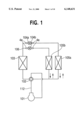
- FIG. 1 is a refrigeration cycle diagram of an air conditioner in a first embodiment of the invention.
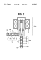
- FIG. 2 is an essential magnified sectional view of an expansion valve and silencer of the first embodiment.
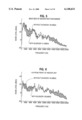
- FIG. 5 is a noise frequency analysis diagram near the side of an indoor heat exchanger of the indoor unit incorporating the expansion valve.
- FIG. 6 is a noise frequency analysis diagram at 1 m from the front of the indoor heat exchanger of the indoor unit incorporating the expansion valve.
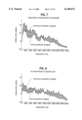
- FIG. 7 is a noise frequency analysis diagram near the side of the indoor heat exchanger of the indoor unit incorporating the expansion valve.
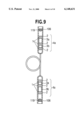
- FIG. 9 is an essential magnified view of a capillary tube and silencer of the first embodiment.
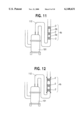
- FIG. 11 is an essential magnified view of a compressor, discharge pipe, and silencer of the second embodiment.
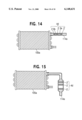
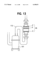
- FIG. 14 is an essential magnified view of an indoor heat exchanger, liquid side lead pipe, and silencer of the second embodiment.
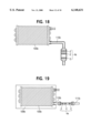
- FIG. 18 is an essential magnified view of another construction of the another indoor heat exchanger, gas side lead pipe, and silencer of the second embodiment.
- FIG. 19 is an essential magnified view of yet another construction of the another indoor heat exchanger, gas side lead pipe, and silencer of the second embodiment.
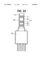
- FIG. 20 is an essential magnified view of a distributor, convergent piping, and silencer of the second embodiment.
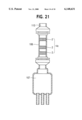
- FIG. 21 is an essential magnified view of another construction of the distributor, convergent piping, and silencer of the second invention.
- FIG. 25 is a refrigeration cycle diagram of a conventional air conditioner.
- a heat pump type refrigeration cycle is composed of a compressor 101, a four-way valve 102, and outdoor heat exchanger 103, an expansion valve 104a, an expansion valve 104b, and indoor heat exchanger 105a, and an indoor heat exchanger 105b, all being coupled by means of a refrigerant piping 106.
- a honeycomb pipe 2 bundling a plurality of fine tubes 1 is inserted into the refrigerant piping 106 connected to the flow-in side and flow-out side of the expansion valve 104a and expansion valve 104b.
- a cylindrical tube 3a whose outside diameter is smaller than the inside diameter of the refrigerant piping 106 is then inserted as a spacer.
- a silencer 4a is formed.
- the cylindrical tube 3a and cylindrical tube 3b of the spacer are different in length from each other, and by extending the refrigerant piping 106, the silencer 4a formed of the honeycomb pipes 2, cylindrical tube 3a and cylindrical tube 3b is fixed in the refrigerant piping 106.
- a strainer 119 is fixed to the refrigerant piping 106 by belting.
- this gas-liquid two-phase refrigerant which is different in density and flow velocity, flows in the refrigerant piping 106, the pressure pulsations increase, and when decompressed in different density states, the noise during decompression increases.
- the refrigerant flowing into the expansion valve 104a is in a gas-liquid two-phase state, the refrigerant passes through the silencer 4a provided in the refrigerant piping 106 at the flow-in side of expansion valve 104a.
- the gas-liquid two-phase refrigerant collides against the honeycomb pipe 2 and receives resistance, and both liquid refrigerant and gas refrigerant are dispersed, and flow into the fine tubes 1 forming the honeycomb pipe 2.
- the refrigerant flowing into each fine tube 1 does not interfere with each other, and flows in each fine tube 1 so as to be homogenized and straightened.
- the refrigerant passing through the fine tubes 1 flows out into the space formed by the cylindrical tube 3b. Since the opening sectional area of the cylindrical tube 3b is relatively larger than the opening sectional area of the honeycomb pipe 2, the refrigerant passing through the cylindrical tube 3b is expanded, and pressure pulsations are attenuated. Furthermore, as the refrigerant passes through the honeycomb pipe 2 and cylindrical tube 3a, it is homogenized, straightened, and enhanced during the pressure pulsation decreasing effect, and then flows into the expansion valve 104a.
- Frequency characteristics of pressure pulsations and frequency characteristics of noise vary depending on the rate of the liquid refrigerant and gas refrigerant in the gas-liquid two-phase refrigerant, but by varying the combination of the length of the cylindrical tube 3a and the length of the cylindrical tube 3b, it is possible to cope with the frequency of high sound pressure level and the frequency of large attenuation, and therefore the noise is reduced and the transmission of pressure pulsations can be attenuated without being affected by variations of cycle state.
- the indoor heat exchanger 105a is operated while the indoor heat exchanger 105b is stopped, and in such a circumstance, the heat exchanger 105b is not closed fully, but is slightly opened, so that the refrigerant may not be stagnant in the stopped indoor heat exchanger 105b and the refrigerant piping 106 connected to the indoor heat exchanger 105b.
- the refrigerant flowing into the expansion valve 104b is a gas-liquid two-phase state large in the rate of gas refrigerant, but in the process of passing through the silencer 4a, homogenization and expansion are repeated, and the flowing noise of the refrigerant can be reduced and pressure pulsations can be attenuated, and moreover, the flowing noise of the refrigerant and the pressure pulsations transmitted from the expansion valve 104b through the refrigerant piping 106 can be also attenuated. Since the silencer 4a is composed by making use of part of the refrigerant piping 106, extra space for installing the silencer 4a is not needed, and the construction of parts is simple, and it is easy to assemble and operate. FIG.
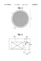
- FIG. 4 shows a state of assembling the expansion valve 104a into the indoor heat exchanger 105a.
- the heating operation is stopped in the shown state, and the noise frequency characteristic when the indoor heat exchanger 105b is put in a heating operation is shown in FIG. 5, FIG. 6, FIG. 7, and FIG. 8.
- the silencer 4a is inserted into two refrigerant pipings 106 communicating with the expansion valve 104a, and fixed by crimping at both ends, in which one honeycomb pipe 2 is used as the silencer 4a, and fine tubes in the honeycomb pipe 2 are 0.2 mm in inside diameter and 5 mm in length, and the aperture rate is about 20%.
- FIG. 5 shows the noise frequency characteristic measured near the side of the indoor heat exchanger 105a
- the fine tubes 1 in the honeycomb pipe 2 are 0.2 mm in inside diameter, and the aperture rate is about 20%.
- Three honeycomb pipes 2 of 5 mm in length are used, and the length of cylindrical tube 3a and cylindrical tube 3b is 5 mm.
- This silencer 4a is inserted into two refrigerant pipings 106 communicating with the expansion valve 104a, and fixed by crimping at both ends. Since the length, 5 mm, is longer than the pipe inside the diameter of 0.2 mm, a sufficient straightening effect is obtained, and transmission of pressure pulsations and noise is attenuated.
- the noise level at 4 kHz or less is substantially reduced, and it is known that the radiation noise from the indoor heat exchanger 105a is smaller.
- the noise level at kHz or more is also reduced, and it is possible to attenuate the irregular refrigerant passing noise in the decompression process of the expansion valve 104a.
- the driving means of the expansion valve is explained as a motor-driven system using a rotor and a stator as shown in FIG. 2, but it may also be other systems. It may be a temperature system for deforming a diaphragm by the gas pressure changing in response to the temperature detected by a temperature sensing tube. It may be a manual system for adjusting the manual throttling action of the refrigerant. It may be a rated pressure system for operating the valve by the pressure in the evaporator. Or it may be a pilot system for operating by the pressure and temperature of the suction vapor coming out from the evaporator.
- the consistent member of the honeycomb pipe used as homogenizing means or refrigerant is a bundle of plural fine tubes, but it may also be constituted by forming communicating holes in a cylinder.
- honeycomb pipes having different opening areas may be arranged adjacently.
- honeycomb pipe is cylindrical, but it may be also formed in a polygonal shape.
- Honeycomb pipes are used as homogenizing means of refrigerant, but porous metal or porous ceramic may be also used.
- the refrigerant piping is expanded, but it may also be realized by press-fitting into the refrigerant piping, or crimping or belting at both ends of the honeycomb pipes.
- a cylindrical tube is used for keeping the clearance between adjacent honeycomb pipes, but the clearance may be also kept by belting or crimping the refrigerant piping, or another shape other than cylindrical can be used for the tube, or structure other than a pipe maybe used.
- honeycomb pipes for forming the silencer is three and the number of cylindrical tubes is two, but each number may be less than three or less than two, or three or more or two or more, respectively.
- Each cylindrical tube differs in length, but tubes of same length may also be used.
- the silencer mounting position is in the refrigerant piping, but it may be formed as part of an expansion valve, or the silencer may be made of one member, and coupled to the refrigerant piping by brazing, soldering, or flaring it into union joint.
- the silencer is provided between the expansion valve and strainer, but the strainer may be disposed between the silencer and the expansion valve.
- a capillary tube may be used as the pressure reducing means.
- the number of indoor heat exchangers is not limited to two, but may be one or three or more.
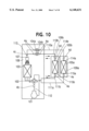
- FIG. 10 is a refrigeration cycle diagram of an air conditioner in a second embodiment of the invention.
- This is a refrigeration cycle of a multi-compartment type air conditioner for conditioning the air in plural rooms composed of a compressor 101 for compressing a refrigerant, a four-way valve 102 for changing over the passage of the refrigerant compressed and discharged by the compressor 101, a multi-pass type outdoor heat exchanger 103 connected to one end of the four-way valve 102, for exchanging heat between fresh air and the refrigerant, having plural refrigerant passages, a distributor 107 for distributing the refrigerant into each passage of the outdoor heat exchanger 103, an outdoor unit 108 composed of expansion valves 104a, 104b and others as decompressing means for decompressing and adjusting the flow rate of the refrigerant being branched and connected from the distributor 107, and indoor units 109a, 109b composed of indoor heat exchangers 105a, 105b and others for exchanging heat between indoor air and the
- a discharge piping 112 for guiding the refrigerant discharged from the compressor 101 into the four-way valve 102 is provided, and a silencer 4b is built in this discharge piping 112, while a silencer 4c is provided in a convergent piping 113 for connecting the expansion valves 104, 104b and the convergent side of the distributor 107.
- a silencer 4d is provided in liquid side lead pipe 114a for connecting the indoor heat exchanger 105a and liquid side piping 110a, and a silencer 4e is provided in a gas side lead pipe 115a for connecting the indoor heat exchanger 105a and gas side piping 111a.
- another silencer 4d is provided in a liquid side lead pipe 114b for connecting the indoor heat exchanger 105b and liquid side piping 110b, and another silencer 4e is provided in a gas side lead pipe 115b for connecting the indoor heat exchanger 105b and gas side piping 111b.
- the operating action is described.
- the gas refrigerant of high temperature and high pressure state compressed and discharged from the compressor 101 flows in the direction indicated by the solid line by means of th four-way valve 102 into the outdoor heat exchanger 103.
- the refrigerant flowing into the outdoor heat exchanger 103 exchanges heat with the fresh air blown in from an outdoor fan (not shown), and is condensed and liquefied.
- the condensed and liquefied refrigerant totally flows into the expansion valve 104a, because the expansion valve 104b provided in the piping system of the indoor unit 109b is not put in operation and is completely closed.
- the flow rate of the refrigerant is adjusted, and the refrigerant is decompressed to be a gas-liquid mixed two-phase state, and passes through the liquid side piping 110a, and flows into the indoor heat exchanger 105a.
- the refrigerant flowing into the indoor heat exchanger 105a exchanges heat with the indoor air blown in from an indoor fan (not shown), and is evaporated and vaporized.
- the indoor air is deprived of heat by heat exchange with the refrigerant, and the indoor space air is cooled.
- the refrigerant evaporated and vaporized by heat exchange with the indoor air returns to the outdoor unit 108 through the gas side pipping 111a, and is sucked into the compressor 101.
- the refrigerant sucked into the compressor 101 is compressed again and discharged, and repeats the same operation.
- the silencer 4b is formed of a honeycomb pipe 2 bundling a plurality of fine tubes 1, a hollow cylindrical tube 3a of which the outside diameter is smaller than the inside diameter of the discharge piping 112, a further honeycomb pipe 2, cylindrical pipe 3b, and yet another further honeycomb pipe 2, which are sequentially inserted into the discharge piping 112.
- the cylindrical tube 3a and cylindrical tube 3b are different in length, and by extending the discharge piping 1 12, the silencer 4b composed of the honeycomb pipes 2, cylindrical tube 3a and cylindrical tube 3b is fixed in the discharge piping 112.
- the gas refrigerant When a gas refrigerant having large pressure pulsation is discharged from the compressor 101, the gas refrigerant is guided into the discharge piping 112, and passes through the silencer 4b incorporated in the discharge piping 112.
- the refrigerant flowing into the silencer 4b first collides against the honeycomb pipe 2 and receives resistance, and the energy is dispersed, then it flows into the fine tubes 1 forming the honeycomb pipe 2. Since the plurality of the fine tubes 1 each have mutually different routes, the refrigerant flowing into each fine tube 1 continues to flow in each fine tube 1 without interfering with the refrigerant flowing in each other fine tube 1, is straightened, and then flows out into the space formed by the cylindrical tube 3a.
- the opening sectional area of the cylindrical tube 3a is relatively wider than the opening sectional area of the honeycomb pipe 2, the refrigerant passing through the cylindrical tube 3a is expanded, and the pressure pulsations are attenuated. Further, as the refrigerant sequentially passes through the another honeycomb pipe 2, cylindrical tube 3b, and yet another honeycomb pipe 2, the straightening effect and pressure pulsation decreasing effect are enhanced, and then it flows out from the silencer 4b. The refrigerant flowing out from the silencer 4b passes through the four-way valve 102, and flows into the outdoor heat exchanger 103.
- the silencer 4b is fixed by extending the discharge piping 112, but it may also be fixed by crimping or belting the piping 112 at both ends of the silencer 4b, and the interval between the adjacent honeycomb pipes 2 is kept by using the cylindrical tube 3a, 3b.
- the interval may also be kept by belting or crimping the piping, or by using tubes of a shape other than cylindrical, or by using structure other than tubes.
- the silencer 4b may be formed as a different part, and attached to the discharge piping 112 by brazing, welding, making a flare connection or the like.
- the silencer 4b may be separately brazed to the discharge piping 112, and the honeycomb pipes 2 are fixed and the interval kept by belting.
- the silencer 4b may be made of a separate part differing in a diameter from that of the discharge piping 112, and is connected to the discharge piping 112 by making a flare connection, and the honeycomb pipes 2 are fixed and the interval kept by crimping.
- the silencer 4d is composed the same as is the silencer 4b, and is formed of a honeycomb pipe 2 bundling a plurality of fine tubes 1, a hollow cylindrical tube 3a of an outside diameter that is smaller than the inside diameter of the liquid side lead pipe 114a, a further honeycomb pipe 2, cylindrical tube 3b, and yet another further honeycomb pipe 2, which are sequentially inserted into the liquid side lead pipe 114a.
- the cylindrical tube 3a and cylindrical tube 3b are different in length, and by extending the liquid side lead pipe 114a, the silencer 4d composed of the honeycomb pipes 2, cylindrical tube 3a and cylindrical tube 3b is fixed in the liquid side lead pipe 114a.
- the refrigerant passes through the silencer 4d provided in the liquid side lead pipe 114a.
- the gas-liquid two-phase refrigerant flowing into the silencer 4d first collides against the honeycomb pipe 2 and receives resistance, and both liquid refrigerant and gas refrigerant are dispersed, and then flow into the fine tubes 1 forming the first honeycomb pipe 2.
- the refrigerant flowing into each fine tube 1 continues to flow in each fine tube 1 without interfering with the refrigerant flowing in each other fine tube 1, so that the refrigerant is homogenized and straightened.
- the refrigerant passing through the fine tubes 1 flows out into the space formed by the cylindrical tube 3a. Since the opening sectional area of the cylindrical tube 3a is relatively wider than the opening sectional area of the honeycomb pipe 2, the refrigerant passing through the cylindrical tube 3a is expanded, and the pressure pulsations are attenuated.
- the refrigerant flowing out from the silencer 4d flows into the indoor heat exchanger 105a.
- the gas-liquid two-phase refrigerant flowing into the indoor heat exchanger 105a is sufficiently homogenized in the gas phase and liquid phase, and is sufficiently attenuated in pressure pulsations, in the indoor heat exchanger 105a it is possible to reduce sufficiently the refrigerant flowing noise due to uneven flow of the gas-liquid two-phase refrigerant and refrigerant radiation noise due to pressure pulsations.
- the silencer 4d is fixed by extending the liquid side lead pipe 114a, but it may be also fixed by crimping or belting at both ends of the silencer 4d, and the interval of the adjacent honeycomb pipes 2 is kept by using the cylindrical tubes 3a, 3b.
- the interval may also be kept by belting or crimping the piping, or by using tubes of a shape than cylindrical, or by using structure other than tubes.
- the silencer 4d instead of placing the silencer 4d in the liquid side lead pipe 114a, the silencer 4d may be formed as a different part, and attached to the liquid side lead pipe 114a by brazing welding, making a flare connection or the like.
- the silencer 4d instead of being disposed the liquid side lead pipe 114a, the silencer 4d may also be placed between the liquid side lead pipe 114a and liquid side piping 110a. For example, as shown in FIG.
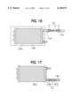
- the silencer 4d may be made of a different part differing in diameter from that of the liquid side lead pipe 114a, and brazed to the liquid side lead pipe 114a, an the honeycomb pipes 2 fixed and the interval kept by crimping. Or, as shown in FIG. 16, the silencer 4d may be made of a separate part and disposed outside of the indoor unit 109a, and may be placed between the liquid side lead pipe 114a and liquid side piping 110a by making a flare connection.
- the operation mode of a heating operation of the indoor unit 109a is described below while referring to FIG. 10.
- the gas refrigerant of high temperature and high pressure compressed and discharged from the compressor 101 flows in the direction indicated by the broken line by means of the four-way valve 102.
- the expansion valve 104b provided in the system of the indoor unit 109b is not put in operation and is set at a minimum opening degree for preventing staying of liquid refrigerant in the indoor heat exchanger 105b, and therefore the refrigerant after passing through the four-way valve 102 is distributed into the indoor units 109a, 109b depending on the opening degree of the expansion valves 104a, 104b, and then flows into the indoor heat exchangers 105a, 105b through the gas side piping 111a, 111b.
- the refrigerant flowing into the indoor heat exchanger 105a exchanges heat with the indoor air blown in from an indoor fan (not shown), and is condensed and liquefied.
- the indoor air absorbs heat by heat exchange with the refrigerant, and heats the indoor space air.
- the refrigerant condensed and liquefied by heat exchange with the indoor air passes through the liquid side piping 110a, and returns to the outdoor unit 108, and is decompressed by the expansion valve 104a to be in gas-liquid mixed two-phase state.
- the refrigerant flowing into the indoor heat exchanger 105b passes through the indoor heat exchanger 105b, flows through the liquid side piping 110b, returns to the outdoor unit 108, is decompressed by the expansion valve 104b, is then converged with th refrigerant passing through the expansion valve 104a, and then flows into the distributor 107.
- the refrigerant from the distributor 107 is divided to flow into each route of the outdoor heat exchanger 103. Inside the outside heat exchanger 103, the refrigerant exchanges heat with the fresh air blown in from an outdoor fan (not shown), and is evaporated and vaporized. The evaporated and vaporized refrigerant passes again through the four-way valve 102, and is sucked into the compressor 101.
- the refrigerant flowing into the indoor heat exchanger 105b in the indoor unit 109b while in a stopped state is very small in flow rate, and a gas-liquid two-phase state of high ratio of gas refrigerant is formed. If the ratio of gas refrigerant and liquid refrigerant in this gas-liquid two-phase refrigerant fluctuates largely, being accompanied by pressure pulsations, that is, if the temperature or pressure state fluctuates significantly when starting the operation of the compressor 101, when stopping the operation, or when changing the rotating speed, or if the refrigeration cycle shows an unstable behavior due to presence of height difference in the configuration of the outdoor unit 108 and indoor unit 109a, refrigerant radiation noise occurs in the indoor heat exchanger 105a due to pulsations of the refrigerant, and also refrigerant flowing noise occurs due to uneven flow of the gas-liquid two-phase refrigerant.
- FIG. 17 is an essential magnified view of the indoor heat exchanger 105b, gas side lead pipe 115b, and silencer 4e, and as shown in the diagram, the gas side lead pipe 115b is joined to the refrigerant flow-in part of the indoor heat exchanger 105b by brazing or welding, and the silencer 4e is included in the gas side lead pipe 115b.
- the silencer 4e is composed the same as is the silencer 4b and silencer 4d, and is formed of a honeycomb pipe 2 bundling a plurality of fine tubes 1, a hollow cylindrical tube 3a of an outside diameter that is smaller than the inside diameter of the gas side lead pipe 115b, a further honeycomb pipe 2, cylindrical tube 3b, and yet another honeycomb pipe 2, which are sequentially inserted into the gas side lead pipe 115b.
- the cylindrical tube 3a and cylindrical tube 3b are different in length, and by extending the gas side lead pipe 115b, the silencer 4e composed of the honeycomb pipes 2, cylindrical tube 3a and cylindrical tube 3b is fixed in the gas side lead pipe 115b.
- the refrigerant passes through the silencer 4e provided in the gas side lead pipe 115b.
- the gas-liquid two-phase refrigerant flowing into the silencer 4e first collides against the first honeycomb pipe 2 and receives resistance, and both the liquid refrigerant and the gas refrigerant are dispersed, and then flow into the fine tubes 1 forming the first honeycomb pipe 2.
- the refrigerant flowing into each fine tube 1 continues to flow in each fine tube 1 without interfering with the refrigerant flowing in each other fine tube 1, so that the refrigerant is homogenized and straightened.
- the refrigerant passing through the fine tubes 1 flows out into the space formed by the cylindrical tube 3a. Since the opening sectional area if the cylindrical tube 3a is relatively wider than the opening sectional area of the honeycomb pipe 2, the refrigerant passing through the cylindrical tube 3a is expanded, and the pressure pulsations are attenuated.
- the refrigerant flowing out from the silencer 4e flows into the indoor heat exchanger 105b.
- the gas-liquid two-phase refrigerant flowing into the indoor heat exchanger 105b is sufficiently homogenized in the gas phase and liquid phase, and is sufficiently attenuated in pressure pulsations, in the indoor heat exchanger 105b it is possible to reduce sufficiently the refrigerant flowing noise due to uneven flow of the gas-liquid two-phase refrigerant and refrigerant radiation noise due to pressure pulsations.
- the silencer 4e is fixed by extending the gas side lead pipe 115b, but it may be also fixed by crimping or belting at both ends of the silencer 4e, and the interval of the adjacent honeycomb pipes 2 is kept by using the cylindrical tubes 3a, 3b.
- the interval may be also kept by belting or crimping the piping, or by using tubes of a shape other than cylindrical, or by using structure other than tubes.
- the silencer 4e instead of placing the silencer 4e in the gas side lead pipe 115b, the silencer 4e may be formed as a different part, and attached to the gas side lead pipe 115b by brazing, welding, making a flare connection or the like.
- the silencer 4e instead of being disposed in the gas side lead pipe 115b, the silencer 4e may be also placed between the gas side lead pipe 115b and gas side piping 111b. For example, as shown in FIG.
- the silencer 4e may be made of a different part differing in diameter from that of the gas side lead pipe 115b, and brazed to the gas side lead pipe 115b, and the honeycomb pipes 2 are fixed and the interval kept by crimping. Or, as shown in FIG. 19, the silencer 4e may be made of a separate part and disposed outside of the indoor unit 109b, and may be placed between the gas side lead pipe 115b and gas side piping 111b by making a flare connection.
- FIG. 20 is an essential magnified view of the distributor 107, convergent piping 113, and silencer 4c.
- the convergent piping 113 is joined to the convergent part of the distributor 107 by brazing or welding, and the silencer 4c is included in the convergent piping 113.
- the silencer 4c is composed the same as are the silencers 4b, 4d, 4e, and is formed of a honeycomb pipe 2 bundling a plurality of fine tubes 1, a hollow cylindrical tube 3a of an outside diameter that is smaller than the inside diameter of the convergent piping 113, a further honeycomb pipe 2, cylindrical tube 3b, and yet another honeycomb pipe 2, which are sequentially inserted into the convergent piping 113.
- the cylindrical tube 3a and cylindrical tube 3b are different in length, and by extending the convergent piping 113, the silencer 4c composed of the honeycomb pipes 2, cylindrical tube 3a and cylindrical tube 3b is fixed in the convergent piping 113.
- the refrigerant passes through the silencer 4c provided in the convergent piping 113.
- the gas-liquid two-phase refrigerant flowing into the silencer 4c first collides against the first honeycomb pipe 2 and receives resistance, and both liquid refrigerant and gas refrigerant are dispersed, and then flow into the fine tubes 1 forming the first honeycomb pipe 2.
- the refrigerant flowing into each fine tube 1 continues to flow in each fine tube 1 without interfering with the refrigerant flowing in each other fine tube 1, so that the refrigerant is homogenized and straightened.
- the refrigerant passing through the fine tubes 1 flows out into the space formed by the cylindrical tube 3a. Since the opening sectional area of the cylindrical tube 3a is relatively wider than the opening sectional area of the honeycomb pipe 2, the refrigerant passing through the cylindrical tube 3a is expanded, and the pressure pulsations are attenuated.
- the refrigerant sequentially passes through the further honeycomb pipe 2, cylindrical tube 3b, and yet another honeycomb pipe 2, the homogenizing, straightening, and pressure pulsation decreasing effects are enhanced, and then it flows out from the silencer 4c.
- the refrigerant flowing out from the silencer 4c flows into the distributor 107.
- the gas-liquid two-phase refrigerant flowing into the distributor 107 is sufficiently homogenized, it is accurately divided in the distributor 107, and is uniformly distributed into plural routes in the outdoor heat exchanger 103, so that heat is exchanged efficiently.
- the gas-liquid two-phase refrigerant flowing into the outdoor heat exchanger 103 is sufficiently homogenized in gas phase and liquid phase, and is sufficiently attenuated in pressure pulsations, and accordingly, in the outdoor heat exchanger 103 it is possible to reduce sufficiently the refrigerant flowing noise due to uneven flow of the gas-liquid two-phase refrigerant and refrigerant radiation noise due to pressure pulsations.
- the silencer 4c is fixed by extending the convergent piping 113, but it may be also fixed by crimping or belting at both ends of the silencer 4c, and the interval between the adjacent honeycomb pipes 2 is kept by using the cylindrical tubes 3a, 3b.
- the silencer 4c may be made of a different part differing in diameter from that of the convergent piping 113, and connected to the convergent piping by making a flare connection, and the honeycomb pipes 2 fixed and the interval kept by crimping.
- the silencer 4c can be inserted into the distributor 107, and fixed thereto, and the intervals between adjacent honeycomb pipes kept by crimping, whereby the distributor 107 is formed integrally with the silencer 4c.
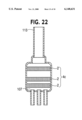
- the outdoor heat exchanger 103 is an air-cooled multi-pass fin and tube heat exchanger, and the silencer 4c is provided in the distributor 107 connected thereto.
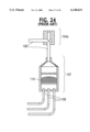
- FIG. 23 is a structural diagram of installing each silencer 4c in the fluid flow-in part of a plate type heat exchanger, and the plate type heat exchanger 116 includes plural laminated plates for forming the fluid passage, and exchanges heat between fluids by passing two kinds of fluids mutually in plural passages.
- the flow of the first fluid flowing in the plate type heat exchanger is indicated by the solid line, and the flow of the second fluid to exchange heat with the first fluid is indicted by the broken line.
- a silencer 4c is provided in the heat exchanger 116 individually at a fluid flow-in part 117a for guiding the first fluid into the plate type heat exchanger 116, a fluid flow-in part 117b for guiding the second fluid into the plate type heat exchanger 116, a fluid flow-out part 118a for sending out the first fluid from the plate type heat exchanger 116, and a fluid flow-out part 118b for sending out the second fluid from the plate type heat exchanger 116.
- the plural fine tubes are same in diameter, but fine tubes of different diameters may be also combined.
- honeycomb pipes having different sized opening areas may be arranged adjacently.
- honeycomb pipe is cylindrical, but it may also be formed in a polygonal shape.
- a cylindrical tube is used for keeping the clearance between adjacent honeycomb pipes, but a polygonal tube may be also used.
- Honeycomb pipes are used as homogenizing means of refrigerant, but porous metal or porous ceramic may be also used.
- honeycomb pipes for forming the silencer is three and the number of cylindrical tubes is two, but each number may be less than three or less than two, or three or more or two or more, respectively.
- Each cylindrical tube differs in length, but tubes of same length may also be used.
- the number of indoor heat exchangers is two, but it may be one or three or more.
- a cooling operation the indoor unit 109a is put in a cooling operation, but the same effects are obtained if the indoor unit 109b is put in the cooling operation, or both indoor units 109a and 109b are put in a cooling operation.
- the indoor unit 109b is kept in stopped state, but the indoor unit 109a may be kept in stopped state, or both indoor units 109a and 109b may be put in a heating operation.
- a plurality of silencers are provided in the refrigeration cycle, but each may be provided individually, or the combination of silencers may be changed.
- Noise and pulsations decreasing effects may also be obtained by disposing the silencers of the invention at other positions generating the refrigerant noise in the refrigeration cycle than those shown in the embodiments.
- the silencer is formed by inserting and fixing a silencer member into the refrigerant piping of a specific sectional area, a silencer capable of omitting an extra space for installing the silencer is presented.
- the invention presents a silencer capable of reducing the refrigerant flowing noise and attenuating transmission of pressure pulsations regardless of cycle state fluctuations.
- the invention also presents an air conditioner capable of homogenizing the refrigeration in the processor of passing the silencer if the refrigerant flowing into the pressure reducing means is in gas-liquid two-phase state.
- the air conditioner is also capable of attenuating transmission of throttle passing noise during decompression, and during pressure pulsation due to decompression by the silencer.
- the invention also presents an air conditioner capable of reducing the pulsations and attenuating transmission of pulsations after the silencer, in the process of passing the refrigerant through the silencer provided in the piping.
- the silencer is connected to the discharge unit of the compressor, and will reduce the pulsations if the pressure pulsations of the refrigerant discharged from the compressor are large.
- the invention also presents an air conditioner capable of straightening and homogenizing the gas refrigerant and liquid refrigerant in the process of passing the refrigerant through the silencer provided in the flow-in part of the evaporator, and also capable of attenuating the refrigerant radiation noise in the evaporator coil unit caused by irregular flow of the gas-liquid two-phase refrigerant when the refrigerant flows into the evaporator in an irregular gas-liquid two-phase state.
- the invention further presents an air conditioner capable of straightening and homogenizing the gas refrigerant and liquid refrigerant in the process of passing the refrigerant through the silencer provided in the refrigerant flow-in part of the distributor, and also capable of attenuating the irregular collision sound of liquid refrigerant and gas refrigerant in the distributor, as well as dividing the flow of refrigerant appropriately into the condenser or evaporator when the refrigerant flows into the distributor and in an irregular gas-liquid two-phase state.
Landscapes
- Engineering & Computer Science (AREA)
- Physics & Mathematics (AREA)
- Mechanical Engineering (AREA)
- Thermal Sciences (AREA)
- General Engineering & Computer Science (AREA)
- Pipe Accessories (AREA)
- Compressor (AREA)
- Exhaust Silencers (AREA)
- Soundproofing, Sound Blocking, And Sound Damping (AREA)
- Compression-Type Refrigeration Machines With Reversible Cycles (AREA)
Abstract
Description
Claims (36)
Applications Claiming Priority (2)
| Application Number | Priority Date | Filing Date | Title |
|---|---|---|---|
| JP10131681A JPH11325655A (en) | 1998-05-14 | 1998-05-14 | Silencers and air conditioners |
| JP10-131681 | 1998-05-14 |
Publications (1)
| Publication Number | Publication Date |
|---|---|
| US6148631A true US6148631A (en) | 2000-11-21 |
Family
ID=15063741
Family Applications (1)
| Application Number | Title | Priority Date | Filing Date |
|---|---|---|---|
| US09/311,343 Expired - Lifetime US6148631A (en) | 1998-05-14 | 1999-05-13 | Silencer and air conditioner |
Country Status (3)
| Country | Link |
|---|---|
| US (1) | US6148631A (en) |
| JP (1) | JPH11325655A (en) |
| CN (1) | CN1143995C (en) |
Cited By (41)
| Publication number | Priority date | Publication date | Assignee | Title |
|---|---|---|---|---|
| US6325296B1 (en) * | 2000-07-26 | 2001-12-04 | Eaton Corporation | Quieting a thermal expansion valve |
| US6450288B1 (en) * | 1998-01-28 | 2002-09-17 | Nikon Corporation | Air-conditioning apparatus, partition and exposure apparatus |
| EP1241418A1 (en) * | 2001-03-14 | 2002-09-18 | LIEBHERR-WERK LIENZ GES. mbH | Refrigeration and/or freezing apparatus |
| WO2002076528A3 (en) * | 2001-03-26 | 2002-12-12 | Datascope Investment Corp | A balloon pump system having a pressure reservoir muffler |
| WO2003027584A1 (en) * | 2001-09-25 | 2003-04-03 | Daikin Industries, Ltd. | Air conditioner |
| EP1371920A2 (en) | 2002-06-12 | 2003-12-17 | Lg Electronics Inc. | Heating/cooling system used in air conditioner |
| EP1291593A3 (en) * | 2001-08-31 | 2004-02-04 | Matsushita Electric Industrial Co., Ltd. | Silencer for air conditioner |
| US6712281B2 (en) * | 2001-10-30 | 2004-03-30 | Tgk Co. Ltd. | Expansion valve |
| US20040139755A1 (en) * | 2003-01-16 | 2004-07-22 | Lg Electronics Inc. | Multi-type air conditioner with plurality of distributor able to be shutoff |
| US20040154323A1 (en) * | 2003-02-11 | 2004-08-12 | Eustice Harry E. | Thermostatic expansion valve exit flow silencer device |
| US20050028553A1 (en) * | 2003-08-07 | 2005-02-10 | Grau Jeffrey M. | Adjustable nozzle distributor |
| US20060150663A1 (en) * | 2005-01-11 | 2006-07-13 | Samsung Electronics Co., Ltd. | Refrigerator |
| US20070245761A1 (en) * | 2006-04-05 | 2007-10-25 | Lee Hyuk S | Noise reduction device and air conditioner having the same |
| US20090000327A1 (en) * | 2005-12-14 | 2009-01-01 | Behr Gmbh& Co.Kg | Heat Pump |
| US20090019871A1 (en) * | 2006-04-07 | 2009-01-22 | Tooru Yukimoto | Expansion Valve and Air Conditioner |
| US20090126398A1 (en) * | 2005-03-25 | 2009-05-21 | Daikin Industries, Ltd. | Refrigeration Apparatus |
| EP2003409A3 (en) * | 2001-01-31 | 2009-08-12 | Mitsubishi Denki Kabushiki Kaisha | Refrigerating cycle apparatus |
| US20090282861A1 (en) * | 2005-09-22 | 2009-11-19 | Daikin Industries, Ltd. | Air conditioning apparatus |
| US20100175409A1 (en) * | 2006-08-11 | 2010-07-15 | Daikin Industries, Ltd. | Air conditioning apparatus |
| CN102631817A (en) * | 2012-04-17 | 2012-08-15 | 卓卫民 | Gas-liquid exchanger and gas-liquid exchange method |
| WO2012156411A1 (en) | 2011-05-18 | 2012-11-22 | Bs2 Ag | Expansion apparatus for heat pumps |
| US20130042643A1 (en) * | 2010-01-11 | 2013-02-21 | Roland Haussmann | Coupling Unit For Connecting The Refrigerant Lines Of A Refrigerant Circuit |
| US20130239602A1 (en) * | 2011-01-31 | 2013-09-19 | Mitsubishi Electric Corporation | Air-conditioning apparatus |
| US20130284413A1 (en) * | 2011-02-04 | 2013-10-31 | Alfa Laval Corporate Ab | Heat exchanger assembly and use of an apparatus in a heat exchanger |
| EP2268979A4 (en) * | 2008-03-06 | 2014-11-26 | Carrier Corp | Split discharge line with integrated muffler for a compressor |
| US20150047806A1 (en) * | 2012-01-13 | 2015-02-19 | Nikon Corporation | Chamber system and heat-insulating panel |
| US9457214B2 (en) | 2009-10-23 | 2016-10-04 | Air Water Safety Service Inc. | Gas fire-extinguishing apparatus |
| WO2017050551A1 (en) * | 2015-09-25 | 2017-03-30 | BSH Hausgeräte GmbH | Refrigerating device having a refrigerant pipe |
| DE102016006481A1 (en) * | 2016-05-25 | 2017-11-30 | Audi Ag | Evaporator injection pipe for a vehicle air conditioning system |
| US20170350631A1 (en) * | 2015-01-16 | 2017-12-07 | Mitsubishi Heavy Industries, Ltd. | Pressure reducing device for cooling system and cooling system |
| US20180016012A1 (en) * | 2016-07-12 | 2018-01-18 | B/E Aerospace, Inc. | System, Methods, and Apparatus for Air Flow Handling in an Aircraft Monument |
| WO2018013410A1 (en) * | 2016-07-13 | 2018-01-18 | Stone Mountain Technologies, Inc. | Electronic expansion valves having multiple orifice plates |
| US20180058727A1 (en) * | 2016-08-31 | 2018-03-01 | Samsung Electronics Co., Ltd. | Air conditioner |
| JP2019023484A (en) * | 2017-07-24 | 2019-02-14 | 株式会社鷺宮製作所 | Electric valve and refrigeration cycle system |
| US10330214B2 (en) * | 2016-09-02 | 2019-06-25 | Fujikoki Corporation | Control valve |
| EP3569954A4 (en) * | 2017-01-12 | 2020-02-12 | Mitsubishi Electric Corporation | EXPANSION VALVE AND REFRIGERATION CIRCUIT THEREFOR |
| US20210102736A1 (en) * | 2019-10-04 | 2021-04-08 | Samsung Electronics Co., Ltd. | Air conditioner |
| US11204029B2 (en) * | 2018-11-14 | 2021-12-21 | Quincy Compressor Llc | Loadless start valve for a compressor |
| EP3992541A4 (en) * | 2019-07-23 | 2022-08-24 | GD Midea Air-Conditioning Equipment Co., Ltd. | INDOOR AIR CONDITIONER UNIT |
| US20230383888A1 (en) * | 2020-10-20 | 2023-11-30 | Chongqing Haier Refrigeration Electric Appliance Co., Ltd. | Noise reduction device and refrigeration device having the same |
| US12163522B2 (en) | 2021-03-31 | 2024-12-10 | Daikin Industries, Ltd. | Compressor containing oil separator with multiple internal muffler spaces |
Families Citing this family (40)
| Publication number | Priority date | Publication date | Assignee | Title |
|---|---|---|---|---|
| JP3395761B2 (en) * | 2000-04-27 | 2003-04-14 | 三菱電機株式会社 | Throttling device, refrigeration cycle device. |
| JP2002195696A (en) * | 2000-12-21 | 2002-07-10 | Matsushita Electric Ind Co Ltd | Air conditioner |
| JP4064762B2 (en) * | 2001-09-07 | 2008-03-19 | 株式会社鷺宮製作所 | Throttle valve device and air conditioner |
| JP2004069166A (en) * | 2002-08-06 | 2004-03-04 | Daikin Ind Ltd | Rectifier and refrigeration system for two-phase refrigerant flow |
| JP4560828B2 (en) * | 2004-03-22 | 2010-10-13 | いすゞ自動車株式会社 | Air compressor intake noise reduction structure |
| JP2007032980A (en) * | 2005-07-28 | 2007-02-08 | Mitsubishi Electric Corp | Expansion valve |
| JP2007032979A (en) * | 2005-07-28 | 2007-02-08 | Mitsubishi Electric Corp | Refrigeration cycle equipment |
| JP2007303461A (en) * | 2006-04-11 | 2007-11-22 | Honda Motor Co Ltd | Air supply system |
| JP4940832B2 (en) * | 2006-08-30 | 2012-05-30 | ダイキン工業株式会社 | Refrigeration equipment |
| JP4983158B2 (en) * | 2006-08-30 | 2012-07-25 | ダイキン工業株式会社 | Refrigeration equipment |
| JP4931684B2 (en) * | 2007-04-25 | 2012-05-16 | 三菱電機株式会社 | Refrigeration cycle equipment |
| US8701628B2 (en) | 2008-07-11 | 2014-04-22 | Tula Technology, Inc. | Internal combustion engine control for improved fuel efficiency |
| JP4988945B2 (en) * | 2009-10-23 | 2012-08-01 | エア・ウォーター防災株式会社 | Gas fire extinguishing equipment |
| JP5972518B2 (en) * | 2009-11-02 | 2016-08-17 | 株式会社コーアツ | Ejection head with a sound deadening function for gas fire extinguishing equipment |
| CN102829581B (en) * | 2011-06-15 | 2015-11-25 | 江森自控空调冷冻设备(无锡)有限公司 | For the gas distribution/junction station of the band noise elimination function of compressor bank refrigeration system |
| CN102518498A (en) * | 2011-12-25 | 2012-06-27 | 浙江大学 | Device for controlling rotary gas-liquid mixed flow noise |
| KR102160310B1 (en) * | 2013-03-06 | 2020-09-28 | 에이비비 터보 시스템즈 아게 | Sound attenuator of an exhaust gas turbocharger |
| JP2015014388A (en) * | 2013-07-03 | 2015-01-22 | 株式会社テージーケー | Filter |
| EP3064868B1 (en) * | 2013-10-29 | 2021-01-20 | Mitsubishi Electric Corporation | Expansion valve |
| JP6324737B2 (en) * | 2014-01-24 | 2018-05-16 | 株式会社日立産機システム | Silencer for ventilator and compressor equipped with silencer |
| CN103925648B (en) * | 2014-04-25 | 2017-01-04 | 江苏兆胜空调有限公司 | A kind of low noise vertical air conditioner machine peculiar to vessel |
| CN107560214A (en) * | 2017-08-02 | 2018-01-09 | 青岛海尔空调电子有限公司 | A control method and device for an expansion valve |
| CN111094876A (en) * | 2017-08-29 | 2020-05-01 | 东芝开利株式会社 | Multi-connected air conditioning system and indoor unit |
| CN108105987B (en) * | 2017-12-18 | 2020-08-28 | 广东美的制冷设备有限公司 | Flow mixer and household electrical appliance |
| JP6938401B2 (en) * | 2018-02-21 | 2021-09-22 | 株式会社鷺宮製作所 | Flow control valve and refrigeration cycle system |
| CN108105988A (en) * | 2018-02-23 | 2018-06-01 | 郭绍华 | Silencer of bundling pipe |
| CN108224660A (en) * | 2018-02-23 | 2018-06-29 | 郭绍华 | New fan of tubulose purification |
| JP7026544B2 (en) * | 2018-03-16 | 2022-02-28 | 大阪瓦斯株式会社 | Noise reduction device |
| CN110857830A (en) * | 2018-08-22 | 2020-03-03 | 青岛海尔智能技术研发有限公司 | Refrigerant noise reduction device and refrigeration equipment |
| CN111829216A (en) * | 2019-04-23 | 2020-10-27 | 浙江盾安禾田金属有限公司 | Electronic expansion valve and refrigerator with same |
| CN110513532A (en) * | 2019-08-15 | 2019-11-29 | 浙江盾安禾田金属有限公司 | Valve muffler and electric expansion valve with the valve muffler |
| CN110736158A (en) * | 2019-08-30 | 2020-01-31 | 珠海格力电器股份有限公司 | piezoelectric photonic crystal type vibration-proof pipeline, vibration-proof method and air conditioner |
| JP7123020B2 (en) * | 2019-09-03 | 2022-08-22 | 株式会社鷺宮製作所 | Electric valve and refrigeration cycle system |
| KR102828843B1 (en) * | 2019-10-04 | 2025-07-04 | 삼성전자주식회사 | Air conditioner |
| CN110864180A (en) * | 2019-11-07 | 2020-03-06 | 哈尔滨工程大学 | High-efficient compact sea water pipeline silencer |
| GB2590667B (en) * | 2019-12-23 | 2022-10-12 | Edwards S R O | Exhaust coupling |
| CN111942103A (en) * | 2020-07-30 | 2020-11-17 | 东风马勒热系统有限公司 | Automobile air conditioner pipeline, automobile refrigeration loop with same and automobile |
| CN114061182A (en) | 2020-07-31 | 2022-02-18 | 开利公司 | Pipeline assembly and refrigerating system |
| CN116792920B (en) * | 2022-03-16 | 2025-09-16 | 青岛海尔空调器有限总公司 | Air conditioner and manufacturing method thereof |
| JP2023155659A (en) * | 2022-04-11 | 2023-10-23 | 横浜ゴム株式会社 | Manufacturing method of resin silencer and resin silencer |
Citations (13)
| Publication number | Priority date | Publication date | Assignee | Title |
|---|---|---|---|---|
| US1014841A (en) * | 1910-07-28 | 1912-01-16 | Frank Van Vleck Morse | Tone-clarifier for talking-machines. |
| US3815379A (en) * | 1972-10-30 | 1974-06-11 | Gen Motors Corp | Unified orifice filter/muffler expansion controller |
| US4381651A (en) * | 1980-07-17 | 1983-05-03 | Nippondenso Co., Ltd. | Silencer in a refrigeration system |
| US4408467A (en) * | 1981-11-23 | 1983-10-11 | Carrier Corporation | Noise suppressing feeder tube for a refrigerant circuit |
| US4955210A (en) * | 1989-08-25 | 1990-09-11 | American Standard Inc. | Capillary tube assembly and method of manufacture |
| JPH05113272A (en) * | 1991-10-23 | 1993-05-07 | Hitachi Ltd | Expansion mechanism of air conditioner |
| JPH05118709A (en) * | 1991-10-23 | 1993-05-14 | Hitachi Ltd | Air conditioner |
| JPH05322379A (en) * | 1992-05-28 | 1993-12-07 | Hitachi Ltd | Air conditioner refrigerant distributor |
| JPH0614685A (en) * | 1992-03-18 | 1994-01-25 | Taisei Corp | Method and structure for preventing aquatic organisms from attaching |
| JPH08313113A (en) * | 1995-05-18 | 1996-11-29 | Hitachi Ltd | Air conditioner refrigerant piping |
| JPH09133434A (en) * | 1995-11-09 | 1997-05-20 | Matsushita Electric Ind Co Ltd | Pulse type electronic expansion valve refrigerant circuit |
| JPH09250845A (en) * | 1996-03-19 | 1997-09-22 | Fujitsu General Ltd | Refrigeration cycle |
| JPH09250844A (en) * | 1996-03-19 | 1997-09-22 | Fujitsu General Ltd | Refrigeration cycle |
Family Cites Families (6)
| Publication number | Priority date | Publication date | Assignee | Title |
|---|---|---|---|---|
| JPS5029305U (en) * | 1973-07-10 | 1975-04-03 | ||
| JPS597364U (en) * | 1982-07-07 | 1984-01-18 | 三菱電機株式会社 | heat exchanger distributor |
| JPH07146032A (en) * | 1993-11-26 | 1995-06-06 | Matsushita Seiko Co Ltd | Expansion valve |
| JP3326260B2 (en) * | 1993-12-01 | 2002-09-17 | 三洋電機株式会社 | refrigerator |
| JPH08296924A (en) * | 1995-04-24 | 1996-11-12 | Matsushita Refrig Co Ltd | Refrigerating equipment |
| JP3435621B2 (en) * | 1996-10-08 | 2003-08-11 | 株式会社日立製作所 | Air conditioner |
-
1998
- 1998-05-14 JP JP10131681A patent/JPH11325655A/en active Pending
-
1999
- 1999-05-13 US US09/311,343 patent/US6148631A/en not_active Expired - Lifetime
- 1999-05-14 CN CNB991067096A patent/CN1143995C/en not_active Expired - Fee Related
Patent Citations (13)
| Publication number | Priority date | Publication date | Assignee | Title |
|---|---|---|---|---|
| US1014841A (en) * | 1910-07-28 | 1912-01-16 | Frank Van Vleck Morse | Tone-clarifier for talking-machines. |
| US3815379A (en) * | 1972-10-30 | 1974-06-11 | Gen Motors Corp | Unified orifice filter/muffler expansion controller |
| US4381651A (en) * | 1980-07-17 | 1983-05-03 | Nippondenso Co., Ltd. | Silencer in a refrigeration system |
| US4408467A (en) * | 1981-11-23 | 1983-10-11 | Carrier Corporation | Noise suppressing feeder tube for a refrigerant circuit |
| US4955210A (en) * | 1989-08-25 | 1990-09-11 | American Standard Inc. | Capillary tube assembly and method of manufacture |
| JPH05118709A (en) * | 1991-10-23 | 1993-05-14 | Hitachi Ltd | Air conditioner |
| JPH05113272A (en) * | 1991-10-23 | 1993-05-07 | Hitachi Ltd | Expansion mechanism of air conditioner |
| JPH0614685A (en) * | 1992-03-18 | 1994-01-25 | Taisei Corp | Method and structure for preventing aquatic organisms from attaching |
| JPH05322379A (en) * | 1992-05-28 | 1993-12-07 | Hitachi Ltd | Air conditioner refrigerant distributor |
| JPH08313113A (en) * | 1995-05-18 | 1996-11-29 | Hitachi Ltd | Air conditioner refrigerant piping |
| JPH09133434A (en) * | 1995-11-09 | 1997-05-20 | Matsushita Electric Ind Co Ltd | Pulse type electronic expansion valve refrigerant circuit |
| JPH09250845A (en) * | 1996-03-19 | 1997-09-22 | Fujitsu General Ltd | Refrigeration cycle |
| JPH09250844A (en) * | 1996-03-19 | 1997-09-22 | Fujitsu General Ltd | Refrigeration cycle |
Cited By (63)
| Publication number | Priority date | Publication date | Assignee | Title |
|---|---|---|---|---|
| US6450288B1 (en) * | 1998-01-28 | 2002-09-17 | Nikon Corporation | Air-conditioning apparatus, partition and exposure apparatus |
| US6325296B1 (en) * | 2000-07-26 | 2001-12-04 | Eaton Corporation | Quieting a thermal expansion valve |
| EP2003409A3 (en) * | 2001-01-31 | 2009-08-12 | Mitsubishi Denki Kabushiki Kaisha | Refrigerating cycle apparatus |
| EP1241418A1 (en) * | 2001-03-14 | 2002-09-18 | LIEBHERR-WERK LIENZ GES. mbH | Refrigeration and/or freezing apparatus |
| WO2002076528A3 (en) * | 2001-03-26 | 2002-12-12 | Datascope Investment Corp | A balloon pump system having a pressure reservoir muffler |
| US6863648B2 (en) | 2001-03-26 | 2005-03-08 | Datascope Investment Corp. | Balloon pump system having a pressure reservoir muffler |
| EP1291593A3 (en) * | 2001-08-31 | 2004-02-04 | Matsushita Electric Industrial Co., Ltd. | Silencer for air conditioner |
| CN1800729B (en) * | 2001-09-25 | 2010-05-12 | 大金工业株式会社 | Air conditioner |
| EP1437561A4 (en) * | 2001-09-25 | 2010-02-17 | Daikin Ind Ltd | AIR CONDITIONER |
| WO2003027584A1 (en) * | 2001-09-25 | 2003-04-03 | Daikin Industries, Ltd. | Air conditioner |
| US6712281B2 (en) * | 2001-10-30 | 2004-03-30 | Tgk Co. Ltd. | Expansion valve |
| EP1371920A3 (en) * | 2002-06-12 | 2005-05-25 | Lg Electronics Inc. | Heating/cooling system used in air conditioner |
| EP1371920A2 (en) | 2002-06-12 | 2003-12-17 | Lg Electronics Inc. | Heating/cooling system used in air conditioner |
| US20040139755A1 (en) * | 2003-01-16 | 2004-07-22 | Lg Electronics Inc. | Multi-type air conditioner with plurality of distributor able to be shutoff |
| US7124595B2 (en) * | 2003-01-16 | 2006-10-24 | Lg Electronics Inc. | Multi-type air conditioner with plurality of distributor able to be shutoff |
| US20040154323A1 (en) * | 2003-02-11 | 2004-08-12 | Eustice Harry E. | Thermostatic expansion valve exit flow silencer device |
| US6810683B2 (en) * | 2003-02-11 | 2004-11-02 | General Motors Corporation | Thermostatic expansion valve exit flow silencer device |
| US7174726B2 (en) * | 2003-08-07 | 2007-02-13 | Parker-Hannifin Corporation | Adjustable nozzle distributor |
| US20050028553A1 (en) * | 2003-08-07 | 2005-02-10 | Grau Jeffrey M. | Adjustable nozzle distributor |
| US20060150663A1 (en) * | 2005-01-11 | 2006-07-13 | Samsung Electronics Co., Ltd. | Refrigerator |
| US20090126398A1 (en) * | 2005-03-25 | 2009-05-21 | Daikin Industries, Ltd. | Refrigeration Apparatus |
| US20090282861A1 (en) * | 2005-09-22 | 2009-11-19 | Daikin Industries, Ltd. | Air conditioning apparatus |
| US20090000327A1 (en) * | 2005-12-14 | 2009-01-01 | Behr Gmbh& Co.Kg | Heat Pump |
| US8806883B2 (en) * | 2005-12-14 | 2014-08-19 | Behr Gmbh & Co. Kg | Heat pump |
| US20070245761A1 (en) * | 2006-04-05 | 2007-10-25 | Lee Hyuk S | Noise reduction device and air conditioner having the same |
| US7849705B2 (en) * | 2006-04-05 | 2010-12-14 | Lg Electronics Inc. | Noise reduction device and air conditioner having the same |
| US20090019871A1 (en) * | 2006-04-07 | 2009-01-22 | Tooru Yukimoto | Expansion Valve and Air Conditioner |
| US20100175409A1 (en) * | 2006-08-11 | 2010-07-15 | Daikin Industries, Ltd. | Air conditioning apparatus |
| EP2268979A4 (en) * | 2008-03-06 | 2014-11-26 | Carrier Corp | Split discharge line with integrated muffler for a compressor |
| US9457214B2 (en) | 2009-10-23 | 2016-10-04 | Air Water Safety Service Inc. | Gas fire-extinguishing apparatus |
| US8966923B2 (en) * | 2010-01-11 | 2015-03-03 | Valeo Klimasysteme Gmbh | Coupling unit for connecting the refrigerant lines of a refrigerant circuit |
| US20130042643A1 (en) * | 2010-01-11 | 2013-02-21 | Roland Haussmann | Coupling Unit For Connecting The Refrigerant Lines Of A Refrigerant Circuit |
| US20130239602A1 (en) * | 2011-01-31 | 2013-09-19 | Mitsubishi Electric Corporation | Air-conditioning apparatus |
| US9599378B2 (en) * | 2011-01-31 | 2017-03-21 | Mitsubishi Electric Corporation | Air-conditioning apparatus |
| US20130284413A1 (en) * | 2011-02-04 | 2013-10-31 | Alfa Laval Corporate Ab | Heat exchanger assembly and use of an apparatus in a heat exchanger |
| US9846001B2 (en) * | 2011-02-04 | 2017-12-19 | Alfa Laval Corporate Ab | Heat exchanger assembly and use of an apparatus in a heat exchanger |
| CH704974A1 (en) * | 2011-05-18 | 2012-11-30 | Bs2 Ag | Expansion apparatus for heat pumps. |
| WO2012156411A1 (en) | 2011-05-18 | 2012-11-22 | Bs2 Ag | Expansion apparatus for heat pumps |
| US20150047806A1 (en) * | 2012-01-13 | 2015-02-19 | Nikon Corporation | Chamber system and heat-insulating panel |
| CN102631817A (en) * | 2012-04-17 | 2012-08-15 | 卓卫民 | Gas-liquid exchanger and gas-liquid exchange method |
| CN102631817B (en) * | 2012-04-17 | 2014-04-09 | 卓卫民 | Gas-liquid exchanger and gas-liquid exchange method |
| US20170350631A1 (en) * | 2015-01-16 | 2017-12-07 | Mitsubishi Heavy Industries, Ltd. | Pressure reducing device for cooling system and cooling system |
| EP3222936A4 (en) * | 2015-01-16 | 2017-12-20 | Mitsubishi Heavy Industries, Ltd. | Pressure reducing device for cooling system and cooling system |
| WO2017050551A1 (en) * | 2015-09-25 | 2017-03-30 | BSH Hausgeräte GmbH | Refrigerating device having a refrigerant pipe |
| DE102016006481A1 (en) * | 2016-05-25 | 2017-11-30 | Audi Ag | Evaporator injection pipe for a vehicle air conditioning system |
| DE102016006481B4 (en) | 2016-05-25 | 2019-03-21 | Audi Ag | Evaporator injection pipe for a vehicle air conditioning system |
| US11097845B2 (en) | 2016-07-12 | 2021-08-24 | B/E Aerospace, Inc. | System and apparatus for air flow handling in an aircraft monument |
| US11235879B2 (en) | 2016-07-12 | 2022-02-01 | B/E Aerospace, Inc. | Aircraft service trolley and galley enclosure therefor |
| USD941744S1 (en) | 2016-07-12 | 2022-01-25 | B/E Aerospace, Inc. | Aircraft galley bay air vent |
| US20180016012A1 (en) * | 2016-07-12 | 2018-01-18 | B/E Aerospace, Inc. | System, Methods, and Apparatus for Air Flow Handling in an Aircraft Monument |
| US11162719B2 (en) | 2016-07-13 | 2021-11-02 | Stone Mountain Technologies, Inc. | Electronic expansion valves having multiple orifice plates |
| WO2018013410A1 (en) * | 2016-07-13 | 2018-01-18 | Stone Mountain Technologies, Inc. | Electronic expansion valves having multiple orifice plates |
| US20180058727A1 (en) * | 2016-08-31 | 2018-03-01 | Samsung Electronics Co., Ltd. | Air conditioner |
| US10739040B2 (en) * | 2016-08-31 | 2020-08-11 | Samsung Electronics Co., Ltd. | Air condtioner |
| US10330214B2 (en) * | 2016-09-02 | 2019-06-25 | Fujikoki Corporation | Control valve |
| EP3569954A4 (en) * | 2017-01-12 | 2020-02-12 | Mitsubishi Electric Corporation | EXPANSION VALVE AND REFRIGERATION CIRCUIT THEREFOR |
| JP2019023484A (en) * | 2017-07-24 | 2019-02-14 | 株式会社鷺宮製作所 | Electric valve and refrigeration cycle system |
| US11204029B2 (en) * | 2018-11-14 | 2021-12-21 | Quincy Compressor Llc | Loadless start valve for a compressor |
| EP3992541A4 (en) * | 2019-07-23 | 2022-08-24 | GD Midea Air-Conditioning Equipment Co., Ltd. | INDOOR AIR CONDITIONER UNIT |
| US20210102736A1 (en) * | 2019-10-04 | 2021-04-08 | Samsung Electronics Co., Ltd. | Air conditioner |
| US11835274B2 (en) * | 2019-10-04 | 2023-12-05 | Samsung Electronics Co., Ltd. | Air conditioner |
| US20230383888A1 (en) * | 2020-10-20 | 2023-11-30 | Chongqing Haier Refrigeration Electric Appliance Co., Ltd. | Noise reduction device and refrigeration device having the same |
| US12163522B2 (en) | 2021-03-31 | 2024-12-10 | Daikin Industries, Ltd. | Compressor containing oil separator with multiple internal muffler spaces |
Also Published As
| Publication number | Publication date |
|---|---|
| CN1143995C (en) | 2004-03-31 |
| JPH11325655A (en) | 1999-11-26 |
| CN1236083A (en) | 1999-11-24 |
| HK1022513A1 (en) | 2000-08-11 |
Similar Documents
| Publication | Publication Date | Title |
|---|---|---|
| US6148631A (en) | Silencer and air conditioner | |
| AU2007236648B2 (en) | Expansion valve and air conditioner | |
| KR100598215B1 (en) | Piping Structure of Air Conditioner Outdoor Unit | |
| CN208845368U (en) | Pulsation and vibration control apparatus | |
| JP3041467B2 (en) | Air conditioner | |
| JP2007085647A (en) | Air conditioner | |
| US7578659B2 (en) | Compressor discharge muffler | |
| EP4579085A1 (en) | Muffler and refrigerating system comprising muffler | |
| KR20050024880A (en) | Structure of piping for air conditioner | |
| JP2008039276A (en) | Refrigerant flow path switching unit and air conditioner using the same | |
| KR100645812B1 (en) | Bundle silencer for indoor unit | |
| EP1371920A2 (en) | Heating/cooling system used in air conditioner | |
| JP6650335B2 (en) | Refrigerant splitter-coupled expansion valve and refrigeration cycle device and air conditioner using the same | |
| JP2001277842A (en) | Air conditioner for automobile | |
| JP2007514127A (en) | High-efficiency turbulence generator for absorption refrigerating / heating multistage regenerator | |
| JP2002061508A (en) | Silencer | |
| KR20090069994A (en) | Cassette type heat-pump air conditioner with stabilized refrigerant-cycle | |
| JPH05322379A (en) | Air conditioner refrigerant distributor | |
| CN220852419U (en) | Air conditioner and compression type refrigerating system thereof | |
| JPH09250844A (en) | Refrigeration cycle | |
| CN210861788U (en) | Reversing device for heat exchange system and heat exchange system | |
| JPH01318866A (en) | Accumulator for compressor | |
| JP6817996B2 (en) | Header for heat exchanger, heat exchanger, outdoor unit and air conditioner | |
| CN116804475A (en) | Air conditioner and compression type refrigerating system thereof | |
| HK1022513B (en) | Silencer and air conditioner |
Legal Events
| Date | Code | Title | Description |
|---|---|---|---|
| AS | Assignment |
Owner name: MATSUSHITA SEIKO CO., LTD., JAPAN Free format text: ASSIGNMENT OF ASSIGNORS INTEREST;ASSIGNORS:WATANABE, MASAHITO;KATSUMI, YOSHIMASA;FUJII, YASUKI;AND OTHERS;REEL/FRAME:010088/0938 Effective date: 19990618 Owner name: MATSUSHITA ELECTRIC INDUSTRIAL CO., LTD., JAPAN Free format text: ASSIGNMENT OF ASSIGNORS INTEREST;ASSIGNORS:WATANABE, MASAHITO;KATSUMI, YOSHIMASA;FUJII, YASUKI;AND OTHERS;REEL/FRAME:010088/0938 Effective date: 19990618 |
|
| STCF | Information on status: patent grant |
Free format text: PATENTED CASE |
|
| FEPP | Fee payment procedure |
Free format text: PAYOR NUMBER ASSIGNED (ORIGINAL EVENT CODE: ASPN); ENTITY STATUS OF PATENT OWNER: LARGE ENTITY |
|
| FPAY | Fee payment |
Year of fee payment: 4 |
|
| FPAY | Fee payment |
Year of fee payment: 8 |
|
| AS | Assignment |
Owner name: MATSUSHITA ECOLOGY SYSTEMS CO., LTD., JAPAN Free format text: CHANGE OF NAME;ASSIGNOR:MATSUSHITA SEIKO CO., LTD.;REEL/FRAME:021994/0939 Effective date: 20030101 Owner name: PANASONIC ECOLOGY SYSTEMS CO., LTD., JAPAN Free format text: CHANGE OF NAME;ASSIGNOR:MATSUSHITA ECOLOGY SYSTEMS CO., LTD.;REEL/FRAME:021994/0931 Effective date: 20081001 |
|
| FEPP | Fee payment procedure |
Free format text: PAYER NUMBER DE-ASSIGNED (ORIGINAL EVENT CODE: RMPN); ENTITY STATUS OF PATENT OWNER: LARGE ENTITY Free format text: PAYOR NUMBER ASSIGNED (ORIGINAL EVENT CODE: ASPN); ENTITY STATUS OF PATENT OWNER: LARGE ENTITY |
|
| FPAY | Fee payment |
Year of fee payment: 12 |