US6047741A - Tool for tying articles, in particular cable harnesses - Google Patents
Tool for tying articles, in particular cable harnesses Download PDFInfo
- Publication number
- US6047741A US6047741A US09/038,550 US3855098A US6047741A US 6047741 A US6047741 A US 6047741A US 3855098 A US3855098 A US 3855098A US 6047741 A US6047741 A US 6047741A
- Authority
- US
- United States
- Prior art keywords
- magazine
- tool
- guide device
- drum
- leg
- Prior art date
- Legal status (The legal status is an assumption and is not a legal conclusion. Google has not performed a legal analysis and makes no representation as to the accuracy of the status listed.)
- Expired - Lifetime
Links
Images


Classifications
-
- B—PERFORMING OPERATIONS; TRANSPORTING
- B65—CONVEYING; PACKING; STORING; HANDLING THIN OR FILAMENTARY MATERIAL
- B65B—MACHINES, APPARATUS OR DEVICES FOR, OR METHODS OF, PACKAGING ARTICLES OR MATERIALS; UNPACKING
- B65B13/00—Bundling articles
- B65B13/02—Applying and securing binding material around articles or groups of articles, e.g. using strings, wires, strips, bands or tapes
- B65B13/025—Hand-held tools
- B65B13/027—Hand-held tools for applying straps having preformed connecting means, e.g. cable ties
Definitions
- the invention relates to a tool for tying articles, in particular cable harnesses
- Cable-tying tools to which the tapes to be used may be fed in the form of a magazine strip which contains the tapes alongside one another and connects them to one another are known.
- the tool has an insertion opening into which the magazine strip is inserted in a predetermined direction.
- the leading end of the magazine strip is then held by the tool, while its trailing end, which may contain a few dozen tapes, floats freely outside the tool.
- the magazine strip is gradually used up and then replaced by a further magazine strip.
- the limited number of tapes contained in one magazine strip is in many cases a definite drawback.
- the invention is therefore based on the object of providing an interchangeable magazine arrangement for the said tools which permits easy attachment of the magazine to the tool.
- the magazine strip is contained in a magazine that can be attached to the tool by means of guide devices.
- the guide devices at least in their part which determines the last part of the attaching movement, are designed such that the outlet opening of the magazine approaches the insertion opening of the tool in approximately the predetermined direction in which the magazine strip is intended to be fed to the insertion opening. It is preferable if the end of the magazine tape that projects out of the outlet opening of the magazine is likewise located in the feed direction. The effect of this is that, when the magazine is being attached to the tool, the magazine tape passes automatically into the insertion opening of the tool, without the end of the magazine strip needing to be laboriously manipulated and positioned. This is true in particular when the magazine is a drum of circular cross section, from which the end of the magazine tape emerges approximately tangentially.
- Attachment of the magazine to the tool takes place in a particularly straightforward manner when, for the connection, provision is made for a plug-in guide in which the cooperating surfaces of the drum and of the tool end in part-surfaces that extend approximately in the feed direction. This also applies when the plug-in guide otherwise extends essentially radially with respect to the drum. Said plug-in guide is then provided at its ends with cam surfaces that extend transversely thereto and, as a result, force that region of the drum that forms the outlet opening of the same to move in the tangential direction.
- the precondition for trouble-free, functionally reliable attachment of the magazine to the tool is that the tool itself is ready to accept the strip end when the magazine is attached.
- a transport member that forms a plurality of tape receptacles and is equipped with a device for the standby positioning of one each of its tape receptacles in a ready-to-feed position behind the insertion opening.
- This member may be, in particular, a roll, which carries the tape receptacles on the circumference and is arranged behind the insertion opening, approximately tangentially to the feed direction.
- FIG. 1 shows the tool with magazine in a perspective illustration
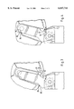
- FIGS. 2 to 4 show the magazine and that part of the tool that cooperates with it in various fitting stages.
- the tool 1 comprises an elongate tool body 2, which can be held in the manner of a pistol by means of a handle 3 and whose tying function is triggered by means of a manual switch.
- the tool body carries wrapping tongs 5, which lead the respective tape around the article to be tied.
- a tape guide channel 6 which runs in the longitudinal direction of the tool body and in which a tape can be advanced to the wrapping tongs 5.
- a pulling-in device 7 which contains a pulling-in drum 8 on whose circumference there are arranged at regular intervals a plurality of projections 9, between which there are recesses 10 which are intended for accepting of individual tapes which are held alongside one another within a magazine strip.
- the magazine strip may be of the type illustrated in EP-B 261 697.
- the pulling-in drum 8 can be driven stepwise, in the direction of arrow 11, in each case through an angular interval corresponding to the projections 9, the standby positions of said drum being placed such that in each case one recess 10 coincides with the advance channel 6.
- the recesses 10 are closed to the outside by housing parts or brackets 12, whose inner surface 13 follows a circular arc about the axis of the pulling-in drum 8 over approximately a semicircle which leads approximately from the upper vertex of the pulling-in drum 8 as far as the advance channel 6.
- the guide surface 13 holds the tapes, which have been inserted in the region of the vertex of the pulling-in drum 8, in the recesses 10 until they reach their destination, the advance channel 6.
- the guide surface 13 ends in the region of the vertex of the pulling-in drum 8 or, projecting a little beyond this in the direction opposite to the advancement direction, in an edge 14.
- This edge together with a housing edge 15 that is located opposite it on the circumference of the advance drum, bounds the insertion opening 16 for the magazine strip.
- the edge 15 is formed by a housing part 17 which, in the vicinity of the edge 15, extends approximately in the direction of a tangent to the core region of the pulling-in drum 8.
- the core region of the pulling-in drum 8 is formed by the sunken base of the recess 10 between the projections 9.
- the guide surface 13 extends, in the vicinity of the edge 14 formed by it, parallel to this direction, approximately tangentially to the outer bounding circle, formed by the tips of the projections 9, of the pulling-in drum 8. This direction corresponds approximately to the predetermined insertion direction 18, in which the magazine strip can run into the pulling-in drum tangentially to the greatest possible extent.
- a magazine 20 Connected to the tool is a magazine 20, in which there are contained, for example, a few hundred tapes in the form of a coherent, wound magazine strip, which is indicated schematically at 21 and whose end 22 emerges approximately tangentially from an opening at the circumference of the magazine.
- the magazine is connected interchangeably to the tool by means of a plug-in connection which is formed, on the one hand, from two parallel struts 23 on the tool body which correspond in shape and, on the other hand, from a receptacle 24 of corresponding shape on the two ends of the magazine 20.
- the struts 23 and receptacles 24 cooperate with side surfaces 25, 26, 27, 28, which form a guide device, which determines the direction of movement of the magazine drum 20 when being attached to the tool. In relation to the drum, these surfaces extend essentially radially. In relation to the tool, they extend upward (when the handle is directed downward), and are inclined to the right just out of the view of the user.
- the magazine drum is therefore not seated centrally over the tool but rather is displaced slightly to the right, in order to give the user an easier view of the tying point.
- the guide devices which have been described up to this point and can be seen in FIG. 1 result in a direction extending essentially from top to bottom for the movement of the magazine when it is being attached to the tool.
- This direction ends when, according to FIG. 3, the corner 29 of the guide surface 25 butts against a part-surface 30 which is angled to the left (in the drawing) at an obtuse angle and forces the corner to move obliquely to the left.
- the guide surface 27 merges into a tab 31 that is directed to the left and to which a cutout 32 corresponds as a continuation of the guide surface 28 on the strut 23.
- the arrangement is such that in the standby position, in which one of the drum recesses 10 coincides with the advance channel 6, the drum 8 also has an open recess 10 turned toward the opening 16.
- a suitable latching mechanism may be provided to hold the advance drum firmly in the standby position.
- FIG. 4 shows the magazine in the end position. It can be seen that the end of the magazine strip has been placed in the drum recess 10 that is located at the insertion opening 16. In order that this happens, the end 22 of the magazine strip 21 which is projecting out of the magazine should lie within a predetermined length range, which is maintained by suitable locking means which may be of a straightforward nature and therefore need not be described. For example, provision may be made at the magazine opening for a cam or hook, which engages in a tape interspace in the magazine strip, in order to hold the latter firmly in the desired position, and which is removed when the magazine is attached to the tool. This task may also be accomplished by a simple adhesive strip.
- the strut 23 and the receptacle 24 provided on the drum are provided, not only at their tool end but also at the other end, with part-surfaces 34, 35 which deviate from the direction of the guide surfaces 25 to 28.
- the part-surface 34 is designed as a rounded edge similar to the corner 29, whereas the part-surface 35 extends approximately parallel to the part-surface 30.
Landscapes
- Engineering & Computer Science (AREA)
- Mechanical Engineering (AREA)
- Basic Packing Technique (AREA)
- Package Frames And Binding Bands (AREA)
Applications Claiming Priority (2)
| Application Number | Priority Date | Filing Date | Title |
|---|---|---|---|
| DE29704402U | 1997-03-11 | ||
| DE29704402U DE29704402U1 (de) | 1997-03-11 | 1997-03-11 | Werkzeug zum Binden von Gegenständen, insbesondere Kabelbäumen |
Publications (1)
| Publication Number | Publication Date |
|---|---|
| US6047741A true US6047741A (en) | 2000-04-11 |
Family
ID=8037286
Family Applications (1)
| Application Number | Title | Priority Date | Filing Date |
|---|---|---|---|
| US09/038,550 Expired - Lifetime US6047741A (en) | 1997-03-11 | 1998-03-11 | Tool for tying articles, in particular cable harnesses |
Country Status (6)
| Country | Link |
|---|---|
| US (1) | US6047741A (de) |
| EP (1) | EP0864496B1 (de) |
| JP (1) | JP2968510B2 (de) |
| DE (2) | DE29704402U1 (de) |
| ES (1) | ES2196408T3 (de) |
| PT (1) | PT864496E (de) |
Cited By (4)
| Publication number | Priority date | Publication date | Assignee | Title |
|---|---|---|---|---|
| US20050005993A1 (en) * | 2003-07-07 | 2005-01-13 | Thomas & Betts International, Inc. | Ergonomic cable tie installation tool |
| US20050178461A1 (en) * | 2004-02-13 | 2005-08-18 | Thomas & Betts International Inc. | Tension and anti-recoil mechanism for cable tie tool |
| US20050217749A1 (en) * | 2004-03-19 | 2005-10-06 | Thomas & Betts International, Inc. | Cable tie tool having variable trigger linkage |
| US7216679B2 (en) | 2004-02-13 | 2007-05-15 | Thomas & Betts International, Inc. | Cable tie tool having modular tool head |
Citations (6)
| Publication number | Priority date | Publication date | Assignee | Title |
|---|---|---|---|---|
| EP0035367A1 (de) * | 1980-02-27 | 1981-09-09 | Bowthorpe-Hellermann Limited | Automatisches Bündelwerkzeug |
| WO1982002867A1 (en) * | 1981-02-20 | 1982-09-02 | Hellermann Ltd Bowthorpe | Automatic tie gun |
| US4371010A (en) * | 1980-11-03 | 1983-02-01 | Thomas & Betts Corporation | Bundling tie applying tool |
| US4495972A (en) * | 1980-02-27 | 1985-01-29 | Bowthorpe-Hellermann Limited | Automatic tie gun |
| EP0261697B1 (de) * | 1983-09-20 | 1991-09-04 | Bowthorpe-Hellermann Limited | Automatischer Bindeapparat |
| US5205328A (en) * | 1992-03-18 | 1993-04-27 | Panduit Corp. | Portable cable tie tool |
-
1997
- 1997-03-11 DE DE29704402U patent/DE29704402U1/de not_active Expired - Lifetime
-
1998
- 1998-01-26 PT PT98101321T patent/PT864496E/pt unknown
- 1998-01-26 EP EP98101321A patent/EP0864496B1/de not_active Expired - Lifetime
- 1998-01-26 ES ES98101321T patent/ES2196408T3/es not_active Expired - Lifetime
- 1998-01-26 DE DE59807918T patent/DE59807918D1/de not_active Expired - Lifetime
- 1998-03-11 JP JP10059333A patent/JP2968510B2/ja not_active Expired - Lifetime
- 1998-03-11 US US09/038,550 patent/US6047741A/en not_active Expired - Lifetime
Patent Citations (7)
| Publication number | Priority date | Publication date | Assignee | Title |
|---|---|---|---|---|
| EP0035367A1 (de) * | 1980-02-27 | 1981-09-09 | Bowthorpe-Hellermann Limited | Automatisches Bündelwerkzeug |
| US4495972A (en) * | 1980-02-27 | 1985-01-29 | Bowthorpe-Hellermann Limited | Automatic tie gun |
| US4640319A (en) * | 1980-02-27 | 1987-02-03 | Bowthorpe-Hellermann Limited | Automatic tie gun |
| US4371010A (en) * | 1980-11-03 | 1983-02-01 | Thomas & Betts Corporation | Bundling tie applying tool |
| WO1982002867A1 (en) * | 1981-02-20 | 1982-09-02 | Hellermann Ltd Bowthorpe | Automatic tie gun |
| EP0261697B1 (de) * | 1983-09-20 | 1991-09-04 | Bowthorpe-Hellermann Limited | Automatischer Bindeapparat |
| US5205328A (en) * | 1992-03-18 | 1993-04-27 | Panduit Corp. | Portable cable tie tool |
Cited By (7)
| Publication number | Priority date | Publication date | Assignee | Title |
|---|---|---|---|---|
| US20050005993A1 (en) * | 2003-07-07 | 2005-01-13 | Thomas & Betts International, Inc. | Ergonomic cable tie installation tool |
| US7086426B2 (en) | 2003-07-07 | 2006-08-08 | Thomas & Betts International, Inc. | Ergonomic cable tie installation tool |
| US20050178461A1 (en) * | 2004-02-13 | 2005-08-18 | Thomas & Betts International Inc. | Tension and anti-recoil mechanism for cable tie tool |
| US7216679B2 (en) | 2004-02-13 | 2007-05-15 | Thomas & Betts International, Inc. | Cable tie tool having modular tool head |
| US7231944B2 (en) | 2004-02-13 | 2007-06-19 | Thomas & Betts International, Inc. | Tension and anti-recoil mechanism for cable tie tool |
| US20050217749A1 (en) * | 2004-03-19 | 2005-10-06 | Thomas & Betts International, Inc. | Cable tie tool having variable trigger linkage |
| US7185680B2 (en) | 2004-03-19 | 2007-03-06 | Thomas & Betts International, Inc. | Cable tie tool having variable trigger linkage |
Also Published As
| Publication number | Publication date |
|---|---|
| EP0864496A1 (de) | 1998-09-16 |
| EP0864496B1 (de) | 2003-04-16 |
| JPH10250707A (ja) | 1998-09-22 |
| PT864496E (pt) | 2003-08-29 |
| ES2196408T3 (es) | 2003-12-16 |
| DE59807918D1 (de) | 2003-05-22 |
| DE29704402U1 (de) | 1998-07-09 |
| JP2968510B2 (ja) | 1999-10-25 |
Similar Documents
| Publication | Publication Date | Title |
|---|---|---|
| US4172523A (en) | Applicator for retaining rings | |
| US4953384A (en) | Magazine-type wiring accessory crimping tool | |
| US6398169B1 (en) | Device for securing longitudinal elements on a panel and tool for installing the same | |
| JPS5832089B2 (ja) | ケツソクヨウノタバネケ−ブルシユウノウカ−トリツジ | |
| PL335442A1 (en) | Component of a screwer | |
| EP0876884B1 (de) | Klingenhalterdose für eine Metallsägemaschine | |
| EP0338779A3 (de) | Knochennagler | |
| US5454900A (en) | Detaping apparatus | |
| EP0205661A2 (de) | Ladevorrichtung für Handfeuerwaffenmagazine | |
| NZ240741A (en) | Herbicide container with guide rib and notch for attachment to dispensing tool | |
| EP1225487A3 (de) | Tonerzuführvorrichtung und Tonerbehälter | |
| US10500705B2 (en) | Fastener holder and dispenser | |
| US4997997A (en) | Coiled article retainer assembly | |
| US4840273A (en) | Tool retention device | |
| JPH0773952A (ja) | ベルトパッケージ | |
| JPH0416101U (de) | ||
| US4881676A (en) | Thumbtack tool | |
| JP2968510B2 (ja) | 結束工具 | |
| US4733460A (en) | Applicator device constituting a magazine for articles to be applied using the device, especially for cable markers | |
| CA2141916A1 (en) | Suction Hose and Filter Holder | |
| US3429431A (en) | Charge of paper clips | |
| JPH11309680A (ja) | 構造物内に挿入すべき構造部品の送出および装着装置 | |
| JP3793303B2 (ja) | 固着具打込機の給送装置 | |
| US6095578A (en) | Devices for handling items with a head and a shank | |
| US5937497A (en) | Method for removing parts from tape |
Legal Events
| Date | Code | Title | Description |
|---|---|---|---|
| AS | Assignment |
Owner name: PAUL HELLERMANN GMBH, GERMANY Free format text: ASSIGNMENT OF ASSIGNORS INTEREST;ASSIGNOR:KURMIS, VIKTOR;REEL/FRAME:010129/0566 Effective date: 19980325 |
|
| STCF | Information on status: patent grant |
Free format text: PATENTED CASE |
|
| FEPP | Fee payment procedure |
Free format text: PAYOR NUMBER ASSIGNED (ORIGINAL EVENT CODE: ASPN); ENTITY STATUS OF PATENT OWNER: LARGE ENTITY |
|
| FPAY | Fee payment |
Year of fee payment: 4 |
|
| FPAY | Fee payment |
Year of fee payment: 8 |
|
| FPAY | Fee payment |
Year of fee payment: 12 |