US6032424A - Block system - Google Patents
Block system Download PDFInfo
- Publication number
- US6032424A US6032424A US09/270,888 US27088899A US6032424A US 6032424 A US6032424 A US 6032424A US 27088899 A US27088899 A US 27088899A US 6032424 A US6032424 A US 6032424A
- Authority
- US
- United States
- Prior art keywords
- block
- opening
- architectural
- blocks
- guide rod
- Prior art date
- Legal status (The legal status is an assumption and is not a legal conclusion. Google has not performed a legal analysis and makes no representation as to the accuracy of the status listed.)
- Expired - Fee Related
Links
- 239000011449 brick Substances 0.000 claims abstract description 14
- 239000002184 metal Substances 0.000 claims description 4
- 230000003014 reinforcing effect Effects 0.000 claims description 4
- 238000000034 method Methods 0.000 abstract description 14
- 238000010276 construction Methods 0.000 abstract description 11
- 238000005266 casting Methods 0.000 abstract 1
- 238000011282 treatment Methods 0.000 description 9
- 125000006850 spacer group Chemical group 0.000 description 8
- 239000000047 product Substances 0.000 description 4
- 239000002023 wood Substances 0.000 description 4
- 238000013461 design Methods 0.000 description 3
- 238000001035 drying Methods 0.000 description 3
- 239000000463 material Substances 0.000 description 3
- 239000011159 matrix material Substances 0.000 description 3
- 238000005516 engineering process Methods 0.000 description 2
- 238000009432 framing Methods 0.000 description 2
- 230000007246 mechanism Effects 0.000 description 2
- 230000015572 biosynthetic process Effects 0.000 description 1
- 239000007795 chemical reaction product Substances 0.000 description 1
- 230000000694 effects Effects 0.000 description 1
- 238000010348 incorporation Methods 0.000 description 1
- 230000002452 interceptive effect Effects 0.000 description 1
- 238000004519 manufacturing process Methods 0.000 description 1
- 238000012986 modification Methods 0.000 description 1
- 230000004048 modification Effects 0.000 description 1
- 239000011435 rock Substances 0.000 description 1
- 238000007789 sealing Methods 0.000 description 1
- 239000007787 solid Substances 0.000 description 1
- 239000004575 stone Substances 0.000 description 1
- 238000005728 strengthening Methods 0.000 description 1
- 238000012360 testing method Methods 0.000 description 1
- 125000000391 vinyl group Chemical group [H]C([*])=C([H])[H] 0.000 description 1
- 229920002554 vinyl polymer Polymers 0.000 description 1
Images


Classifications
-
- E—FIXED CONSTRUCTIONS
- E04—BUILDING
- E04B—GENERAL BUILDING CONSTRUCTIONS; WALLS, e.g. PARTITIONS; ROOFS; FLOORS; CEILINGS; INSULATION OR OTHER PROTECTION OF BUILDINGS
- E04B2/00—Walls, e.g. partitions, for buildings; Wall construction with regard to insulation; Connections specially adapted to walls
- E04B2/84—Walls made by casting, pouring, or tamping in situ
- E04B2/86—Walls made by casting, pouring, or tamping in situ made in permanent forms
- E04B2/8623—Walls made by casting, pouring, or tamping in situ made in permanent forms with spacers and at least one form leaf being monolithic
- E04B2/8629—Walls made by casting, pouring, or tamping in situ made in permanent forms with spacers and at least one form leaf being monolithic with both form leaves and spacers being monolithic
-
- B—PERFORMING OPERATIONS; TRANSPORTING
- B22—CASTING; POWDER METALLURGY
- B22C—FOUNDRY MOULDING
- B22C9/00—Moulds or cores; Moulding processes
- B22C9/22—Moulds for peculiarly-shaped castings
- B22C9/24—Moulds for peculiarly-shaped castings for hollow articles
-
- B—PERFORMING OPERATIONS; TRANSPORTING
- B28—WORKING CEMENT, CLAY, OR STONE
- B28B—SHAPING CLAY OR OTHER CERAMIC COMPOSITIONS; SHAPING SLAG; SHAPING MIXTURES CONTAINING CEMENTITIOUS MATERIAL, e.g. PLASTER
- B28B13/00—Feeding the unshaped material to moulds or apparatus for producing shaped articles; Discharging shaped articles from such moulds or apparatus
- B28B13/04—Discharging the shaped articles
- B28B13/06—Removing the shaped articles from moulds
-
- B—PERFORMING OPERATIONS; TRANSPORTING
- B28—WORKING CEMENT, CLAY, OR STONE
- B28B—SHAPING CLAY OR OTHER CERAMIC COMPOSITIONS; SHAPING SLAG; SHAPING MIXTURES CONTAINING CEMENTITIOUS MATERIAL, e.g. PLASTER
- B28B23/00—Arrangements specially adapted for the production of shaped articles with elements wholly or partly embedded in the moulding material; Production of reinforced objects
- B28B23/0056—Means for inserting the elements into the mould or supporting them in the mould
-
- B—PERFORMING OPERATIONS; TRANSPORTING
- B28—WORKING CEMENT, CLAY, OR STONE
- B28B—SHAPING CLAY OR OTHER CERAMIC COMPOSITIONS; SHAPING SLAG; SHAPING MIXTURES CONTAINING CEMENTITIOUS MATERIAL, e.g. PLASTER
- B28B23/00—Arrangements specially adapted for the production of shaped articles with elements wholly or partly embedded in the moulding material; Production of reinforced objects
- B28B23/02—Arrangements specially adapted for the production of shaped articles with elements wholly or partly embedded in the moulding material; Production of reinforced objects wherein the elements are reinforcing members
- B28B23/022—Means for inserting reinforcing members into the mould or for supporting them in the mould
- B28B23/024—Supporting means
-
- B—PERFORMING OPERATIONS; TRANSPORTING
- B28—WORKING CEMENT, CLAY, OR STONE
- B28B—SHAPING CLAY OR OTHER CERAMIC COMPOSITIONS; SHAPING SLAG; SHAPING MIXTURES CONTAINING CEMENTITIOUS MATERIAL, e.g. PLASTER
- B28B7/00—Moulds; Cores; Mandrels
- B28B7/0029—Moulds or moulding surfaces not covered by B28B7/0058 - B28B7/36 and B28B7/40 - B28B7/465, e.g. moulds assembled from several parts
- B28B7/0035—Moulds characterised by the way in which the sidewalls of the mould and the moulded article move with respect to each other during demoulding
- B28B7/0044—Moulds characterised by the way in which the sidewalls of the mould and the moulded article move with respect to each other during demoulding the sidewalls of the mould being only tilted away from the sidewalls of the moulded article, e.g. moulds with hingedly mounted sidewalls
-
- B—PERFORMING OPERATIONS; TRANSPORTING
- B28—WORKING CEMENT, CLAY, OR STONE
- B28B—SHAPING CLAY OR OTHER CERAMIC COMPOSITIONS; SHAPING SLAG; SHAPING MIXTURES CONTAINING CEMENTITIOUS MATERIAL, e.g. PLASTER
- B28B7/00—Moulds; Cores; Mandrels
- B28B7/0064—Moulds characterised by special surfaces for producing a desired surface of a moulded article, e.g. profiled or polished moulding surfaces
-
- B—PERFORMING OPERATIONS; TRANSPORTING
- B28—WORKING CEMENT, CLAY, OR STONE
- B28B—SHAPING CLAY OR OTHER CERAMIC COMPOSITIONS; SHAPING SLAG; SHAPING MIXTURES CONTAINING CEMENTITIOUS MATERIAL, e.g. PLASTER
- B28B7/00—Moulds; Cores; Mandrels
- B28B7/10—Moulds with means incorporated therein, or carried thereby, for ejecting or detaching the moulded article
-
- B—PERFORMING OPERATIONS; TRANSPORTING
- B28—WORKING CEMENT, CLAY, OR STONE
- B28B—SHAPING CLAY OR OTHER CERAMIC COMPOSITIONS; SHAPING SLAG; SHAPING MIXTURES CONTAINING CEMENTITIOUS MATERIAL, e.g. PLASTER
- B28B7/00—Moulds; Cores; Mandrels
- B28B7/16—Moulds for making shaped articles with cavities or holes open to the surface, e.g. with blind holes
- B28B7/162—Moulds for making shaped articles with cavities or holes open to the surface, e.g. with blind holes for building blocks or similar block-shaped articles
-
- B—PERFORMING OPERATIONS; TRANSPORTING
- B28—WORKING CEMENT, CLAY, OR STONE
- B28B—SHAPING CLAY OR OTHER CERAMIC COMPOSITIONS; SHAPING SLAG; SHAPING MIXTURES CONTAINING CEMENTITIOUS MATERIAL, e.g. PLASTER
- B28B7/00—Moulds; Cores; Mandrels
- B28B7/16—Moulds for making shaped articles with cavities or holes open to the surface, e.g. with blind holes
- B28B7/18—Moulds for making shaped articles with cavities or holes open to the surface, e.g. with blind holes the holes passing completely through the article
- B28B7/183—Moulds for making shaped articles with cavities or holes open to the surface, e.g. with blind holes the holes passing completely through the article for building blocks or similar block-shaped objects
-
- B—PERFORMING OPERATIONS; TRANSPORTING
- B28—WORKING CEMENT, CLAY, OR STONE
- B28B—SHAPING CLAY OR OTHER CERAMIC COMPOSITIONS; SHAPING SLAG; SHAPING MIXTURES CONTAINING CEMENTITIOUS MATERIAL, e.g. PLASTER
- B28B7/00—Moulds; Cores; Mandrels
- B28B7/26—Assemblies of separate moulds, i.e. of moulds or moulding space units, each forming a complete mould or moulding space unit independently from each other
-
- E—FIXED CONSTRUCTIONS
- E04—BUILDING
- E04B—GENERAL BUILDING CONSTRUCTIONS; WALLS, e.g. PARTITIONS; ROOFS; FLOORS; CEILINGS; INSULATION OR OTHER PROTECTION OF BUILDINGS
- E04B2/00—Walls, e.g. partitions, for buildings; Wall construction with regard to insulation; Connections specially adapted to walls
- E04B2/02—Walls, e.g. partitions, for buildings; Wall construction with regard to insulation; Connections specially adapted to walls built-up from layers of building elements
- E04B2/14—Walls having cavities in, but not between, the elements, i.e. each cavity being enclosed by at least four sides forming part of one single element
- E04B2/16—Walls having cavities in, but not between, the elements, i.e. each cavity being enclosed by at least four sides forming part of one single element using elements having specially-designed means for stabilising the position
-
- E—FIXED CONSTRUCTIONS
- E02—HYDRAULIC ENGINEERING; FOUNDATIONS; SOIL SHIFTING
- E02D—FOUNDATIONS; EXCAVATIONS; EMBANKMENTS; UNDERGROUND OR UNDERWATER STRUCTURES
- E02D29/00—Independent underground or underwater structures; Retaining walls
- E02D29/02—Retaining or protecting walls
-
- E—FIXED CONSTRUCTIONS
- E04—BUILDING
- E04B—GENERAL BUILDING CONSTRUCTIONS; WALLS, e.g. PARTITIONS; ROOFS; FLOORS; CEILINGS; INSULATION OR OTHER PROTECTION OF BUILDINGS
- E04B2/00—Walls, e.g. partitions, for buildings; Wall construction with regard to insulation; Connections specially adapted to walls
- E04B2/02—Walls, e.g. partitions, for buildings; Wall construction with regard to insulation; Connections specially adapted to walls built-up from layers of building elements
- E04B2002/0256—Special features of building elements
- E04B2002/0258—Gripping or handling aids
Definitions
- the prior art shows embedded lifting mechanisms.
- the prior art also shows building members and concrete building members having hollow interiors.
- the prior art also shows building members assembled to receive a concrete matrix.
- the invention is a specialized building block and a building process using the specialized blocks for constructing walls, building exteriors and decorative architectural detail such as cornices, eaves, window and door casings and Lintels built independently and in conjunction with walls.
- a process for constructing the blocks is also taught.
- the invention uses blocks which, when assembled, have a series of intersecting chambers which allow for a continuous concrete pour throughout the structure in order to secure the blocks together.
- the blocks are defined by specialized exterior features, by the channel system, by the cage and opening layout for lifting and centering one block on top of another.
- the products are pre-fabricated and stacked for shipping and construction.
- No exterior finishes are required to be added during construction because all desired finishes and desired shapes, both decorative and functional, are already part of this structural product.
- the structural integrity of the building (framing, etc), the interior finish surfaces, the weather controlling aspect, and the complete decorative aspect are all one and the same in this product.
- Another object of the invention is to provide a block which can easily be lifted in place by at least one lifting rod and thereafter stacked and filled with concrete or other matrix without the rod interfering with the concrete pour.
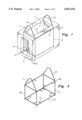
- FIG. 1 is a plan view of one of the blocks described by the invention.
- FIG. 2(a) is a plan view of a plug having a notched centering means and a cage mounted on the centering means with a single lifting rod.
- FIG. 2(b) is a plan view of a jig having a notched centering means and raised guides for building properly centered cages.
- FIG. 3 is a plan view of a cage having lifting rods.
- FIG. 4 is a cut away view of a structural wall detail, here a window frame, of the type shown in FIG. 5 through the 4--4 axis of FIG. 5.
- FIG. 4a is a cross section of the detail shown in FIG. 4 through the 4a--4a axis.
- FIG. 4b is a cross section of FIG. 4a through the 4b--4b axis.
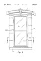
- FIG. 5 is a window frame incorporating the structure described herein.
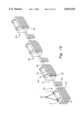
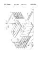
- FIG. 6 is an exploded view of a mold used for making blocks.
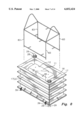
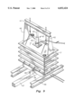
- FIG. 7 is a cross sectional view of a wall in a two story structure using the technology described herein.
- FIG. 8 shows an assembled mold with a modified cage.
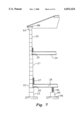
- FIG. 9 shows a press and pull mechanism for removing plugs from set pours in the mold.
- FIG. 10 shows a plan view of the structure described in FIG. 7.
- FIG. 11 shows an architectural detail of a window, such as is shown in FIG. 5, during the assembly process.
- FIG. 12 shows a lintel block used in the construction of the window shown in FIG. 11.
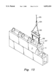
- FIG. 13 shows a wall being assembled using the blocks described herein.
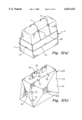
- FIG. 14 shows the wall of FIG. 13 with a cornice and top plate.
- FIG. 15 shows an interior view of a mold wall detail.
- FIG. 16 shows a cross section of the wall detail of FIG. 15 through the 16--16 axis.
- FIG. 17 shows an interior view of an alternative mold wall detail.
- FIG. 18a shows a cross section of the mold wall detail of FIG. 17 through the 18a--18a axis using short studs as an attachment means.
- FIG. 18b shows a cross section of the mold wall detail of FIG. 17 through the 18b--18b axis using a long stud as an attachment means
- FIG. 19 shows a block wall produced using a mold detail such as that shown in FIG. 15.
- one invention comprises a specialized block having a special purpose for construction of a building.
- the blocks can be understood by reference to FIG. 1 which shows a perspective view of a block utilizing the construction techniques set out herein.
- This block comprises a block top opening 1 and at least one block additional opening, here a bottom opening 4 and a side opening 5. At least a portion of the internal area of the block is hollow in order to provide a passage which allows the block top opening 1 to communicate with the block bottom opening 4 or side opening 5 or both.
- the bottom opening 4 is larger than the top opening 1.
- the bottom opening 4 is large enough to receive first and second guide rods 6 and 7 respectively.
- the guide rods 6 may come up from the center of the top opening 1 or from the walls on either side of the top opening 1.
- the guide rods 6 are preferably curved at the top so that as a top block is lowered by its own guide rods 6 and 7 onto a lower block the bottom opening 4 of the top block accepts the guide rods 6 and 7 of the bottom block into the bottom opening 4 and the bottom edges 14 of the bottom opening 4 are guided by the guide rod 6 into the appropriate location.
- at least a first guide rod 6 and a second guide rod 7 are present in the preferred embodiment for proper centering of a top block with a bottom block as shown in FIG. 13.
- the bottom opening 4 is larger than the top opening 1 so that the guide rods will appropriately guide the bottom opening in place over a lower brick and also to make the concrete pours more even by preventing concrete build up within the pour.
- the edges 14 of the bottom opening 4 may be notched so that these notches 14(a) could be guided over the rods 6 and 7.
- the spacing and use of the guide rods 6 and 7 defines how many are needed and what shapes are possible.
- the size of the rods is governed by the strength requirements since the rods serve a lifting purpose and a guiding purpose.
- the rods act as reinforcing rods when concrete is poured into the assembled blocks.
- the second guide rod 7 is shown here as being parallel to the first guide rod 6. However, it can easily be seen that it may be at an angle off parallel all the way to being perpendicular to form a dome for guiding a second block onto a first block.
- the rods for easy lifting and the rods travel from the left side 9 of the top opening 1 to the right side 10 of the top opening 1.
- concrete may be poured through the top block top opening 1 and then it travels through to other blocks which have openings aligned with this top block.
- Guide rods may extend from the side openings for a similar purpose although this is not necessary in the preferred embodiment given the function of the rods to allow for easy lifting and placement of the blocks.
- the edges of the plug 11 are curved.
- a portion of the guide rods lays on the notches 12 of the plug so that the cage is properly aligned.
- the cage side may have an upper and lower part running along the side of the plug.
- the internal cage 3 may be built on a jig which has top notches 73 and bottom notches 74 to receive the top frame 36 and bottom frame 37 respectively. Since the rods 6 and 7 must extend over the top, raised guides 75 may be used to assure the proper height of the guide rods 6 and 7.
- the raised guides 75 may define raised notches 76 which receive the guide rods 6 and 7 as they are run from one side of the cage over the raised guides 75 to the other side of the cage.
- right side notches 77 and 78 and left side notches 79 and 80 are provided. Rod 6 is attached from the top frame 36, fit through right notch 78, into the nearer guide 75 within the notch 76, through the left notch 80 and back onto the far side of the top frame 36. This same design arrangement is provided for the other rod 7.
- short side spacer alignment 81 and long side spacer alignment 62 may be used to show where the spacer is to be inserted and to set the distance if the spacer 15 extends inward from the cage.
- FIG. 3 shows the use of two rods 6 and 7.
- an internal cage 3 is built within the block itself.
- Cross rods may extend through the center of the block between sides of the internal cage 3 in order to add additional re-enforcing strength to the concrete poured within the blocks although this is typically unnecessary.
- spacers 15 as shown in FIG. 3 throughout the cage 3 allows the cage to be centered on plug 11 even without notches 12.
- the cage 3 is preferably comprised of a bottom frame 37, a side frame 38 and a top frame 36 formed of interlocking metal bars of sufficient thickness to support the blocks when lifted by support bars 6 and 7 when the block is lifted. While the support rods 6 and 7 are shown at either side, of the cage, their number and location is discretionary as long as they serve their guiding function, their re-enforcing function, and their lifting function.
- the internal cage not only allows for the lifting and strengthening the position of the guide rods but also adds structural strength to the concrete block 1.
- the cage may be partially or completely encased in concrete although at least a portion of it is preferably encased in concrete so that the block may be lifted by the rods 6 and 7 extending from the cage 3.
- the cage may be suspended within the mold for the block.
- the guide rod 6 may be centered on a notch 12 on a plug 11 to properly center the cage and this may also be done with spacers 15.
- FIG. 6 shows the mold assembly. During assembly, a cage as shown in FIG. 2a or 3 is put in place before side plugs are installed.
- FIG. 6 shows the assembly of a mold for manufacturing blocks with bottom and side openings.
- the mold consists of a bottom plug 11 which is fitted within an opening in the base 19 of the mold. This bottom plug 11 will form the top opening 1 and bottom opening 4 if it fits all the way through the block. If only a top or bottom opening is desired, the plug will not pass all the way through.
- the cage 3 also shown in FIG. 3 is then put on top of this plug 11 and the side walls 17 and 17a are attached so that either of the side plugs 16 or 16a would touch the bottom plug 11, if it is desired to have either of the side openings 5 in the block.
- both the bottom plug 11 and side plugs 16 are tapered from the base 19 or wall 17, respectively, to a more narrow end to make removal easier. Since the bottom plug 11 is tapered from a wide base to a narrow top, the top face 16b of the side plug 16a is tapered so as to fit against the side face 11a of the bottom plug 11. This fit leaves little or no concrete between the faces 16a and 11a or leaves a thin enough sheet of concrete so that it may be easily punched out. Assembly bars 26 are inserted through the base 19 below the bottom of the plug 11 to hold the plug 11 in place during the pour. These rods 26 will later be removed to allow the plug to be removed.
- c-clamps 28 attached to posts 29 on each of the two separate side walls 17 and 17a of the mold serve to hold the side walls together relative to one another as the mold is poured.
- the base 19 is also held to the side walls 17 and 17a by way of clamps 39.
- FIG. 8 shows the internal cage out of the assembled mold, but as discussed above, referring to FIG. 6, typically the cage would be put in before any side plugs 16.
- the bottom of the cage 3 is open on the side.
- the side legs 83 can fit on either side of the side wall plugs 16 and 16(a) shown in FIG. 8.
- concrete can be poured and the entire mold allowed to cure, fully or partially, at which point the plugs are pulled, pressed or knocked out and the block is ready to use.
- the ridges 23 which may rise from the bottom plug 11 to provide guides in the finished block which receive the support bars 6 and 7 shown in FIG. 3 when one block is placed atop another.
- the blocks may be of a variety of shapes without departing from the concept embodied herein.
- the plugs 11 are then drawn out or pressed out or knocked out of the center of the block.
- the plugs 11 may have notches 12 which allow for them to assist in the alignment of the cage 3.
- the edges 13 of the plug 11 are rounded and the sides 16 of the plug are tapered in order to assist with the plug's removal. Tapering also leads to the larger size of the bottom of the block opening versus the top block opening 1.
- the plug 11 may be removed by jacking the plug 11 out or by pulling the plug out from the bottom or a combination of the two techniques. This may be done while the concrete is fully hardened or during the drying process when the mold is sufficiently set in order to allow the passages defined by the plugs to remain in place. There may be small holes in the plugs which receive pins to test the concrete for drying.
- brace supports 40 support a brace 41 against the sides of the mold.
- the brace 41 is also supported against the jack arm 44 by chains 42 hooked into the guiding rods 6 and 7 of the block.
- a jack is inserted between the plug 11 and the brace 41 and as the jack arm 44 pushes against the brace 41, the jack base 45 pushes the plug 11 out.
- FIG. 9 also shows the use of a eye-bolt 46 built into the bottom of the plug 11.
- This eye-bolt 46 may be attached to a hook 48 on a beam 47. This arrangement is held off the floor by placing the mold on I-beams 49 and the beam 47 is pressed to the floor, pulling the plug 11 from the mold.
- These same technologies may be used on the side plugs which are smaller and require less stress to remove.
- FIG. 4 shows the use of traditional framing on offsets created by the construction techniques utilized herein.
- 8 inch wide [0.203 m] frame blocks 31 extend around the window 50.
- the 8 inch [0.203 m] frame blocks 31 are offset to stick out from the 16 inch [0.406 m] structural blocks 21 by a predetermined distance 31(c).
- the front face 31(a) of the blocks facing outward may be slightly less far out than the cast sill 51 on which the 8 inch [0.203 m] frame blocks 31 and window 50 rest.
- the actual window 50 is recessed from the front face 31(a) of the 8 inch [0.203 m] frame blocks 31.
- the interior walls 52 are mounted on studs 53 in the manner well known in the art.
- the window is recessed within the walls by a window casing 54 of the type also known in the art.
- the 8 inch [0.203 m] frame blocks 31 abut the 16 inch [0.406 m] structural blocks 21 which are here thirty inches [0.762 m] long and the frame blocks 31 may be indented within the 8 inch difference [0.203 m].
- the side openings of the frame blocks 31 and structural blocks 21 would preferably be aligned as shown in FIG. 4 even though the blocks themselves are of different widths.
- a solid cast cornice or lintel 55 may be placed atop the window frame described by the 8 inch [0.203 m] frame blocks 31. This cornice 40 would be supported by and integral with the 8 inch [0.203 m] frame blocks.
- FIG. 4(a) shows a side section of the cross section shown in FIG. 4.
- lintel 55 of the window treatment which is shown in this FIG. 4(a)
- structural and design details may be incorporated into a poured block.
- the structural detail here is a plate 25 which receives a beam 24 atop a wooden wall stud 53 which rests on the plate 25.
- the plate is a part of the poured block.
- this lintel block 55 incorporates a design exterior treatment 72. While both the plate 25 and exterior treatment 72 are shown here in a single block, it is obvious that either detail may be incorporated into a block without the other.
- FIGS. 4, 5 and 10 Architectural details are shown in FIGS. 4, 5 and 10 for an exterior window 50.
- the casing for the window 50 is built onto special blocks set as shown in FIG. 11 among the remaining framework.
- FIG. 11 shows how the window treatment described in FIGS. 4 and 5 would be assembled with a lintel 55 which, here, has neither a special exterior treatment nor a plate.
- the 8-inch [0.203 m] frame blocks 31 are in place and the lintel 55 is being lowered by way of the support rods 6 and 7.
- a side opening 56 in the lintel may allow concrete to connect the lintel 55 to the 16 inch blocks on either side which would have cooperating openings.
- the lintel 55 may also have bottom openings (not shown) to allow concrete coming into the lintel's interior through lintel top openings 57 or side openings 56 to move into the top openings in the top most 8-inch [0.203 m] frame block. From there, the concrete would pass into the lower 8-inch [0.203 m] frame blocks sealing the structure together.
- the lintel 55 may be placed on top.
- top openings 57 may be multiple top openings 57 to allow pours down the left and right 8-inch [0.203 m] frame blocks 31.
- bottom openings 4 there would be corresponding multiple bottom openings 4 (not shown) to allow the concrete to flow through to top openings in the 8-inch [0.203 m] frame blocks 31 below the top openings 57.
- FIG. 12 shows a detailed view of the lintel 55 shown in FIG. 11.
- FIG. 7 shows a side cross section of a house where a series of blocks as shown in FIG. 1 are stacked one on top of the other and as can be seen here 12-inch [0.305 m] small blocks 20 may have holes bottom holes in alignment, not only with each other, but also with 16-inch [0.406 m] structural blocks 21 by virtue of having the location of the plug off center during their formation in order to allow for the placement of a joist 24 on a plate 25 atop the 16-inch [0.406 m] structural block 21.
- This plate 25 is the area the larger 16-inch [0.406 m] structural blocks 21 which is not covered by the smaller 12-inch [0.305 m] small blocks 20. This is compared with the formed plate 25 which is an integral part of the top block 55 shown in FIG. 4(a).
- 16-inch [0.406 m] structural blocks 21 are aligned with 18-inch [0.457 m] middle blocks 22 to allow for two by four wall lumber 27 to be run off of a sixteen inch [0.406 m] I-Joist 26 which in turn rests on a plate 28 which is the uncovered area of the 22-inch [0.559 m] bottom block 23 when the 18-inch [0.457 m] middle block 22 is placed on the larger block as shown in FIG. 7.
- the 16-inch [0.406 m] structural blocks and 18-inch[0.457 m] middle blocks 22 may have bottom openings 4 which are offset so as to be aligned with the top openings on 22-inch [0.559 m] bottom blocks 23 and may define an offset 28 on which to place a joist 26 to support the construction within the walls so described.
- the purpose being to incorporate the architectural details into the blocks, rather than to attach these details at a latter point in time.
- FIG. 7 also shows how the blocks may be built directly off of the foundation 96 or how a intermediary foundation block 95 may be placed on the foundation 96 which in turn supports seals 94.
- FIG. 13 shows several blocks being stacked together utilizing the method taught hereunder, utilizing a crane (not shown) to lower blocks via a hook 84 and chain 85 attached to a small spacing beam 86 which is attached by two second hooks 87 and support chains 88 attached to the block support rods 6 and 7. It can be seen that the blocks may be offset to provide a more interwoven structural cross section.
- FIG. 14 shows the wall of FIG. 13 with a top plate where several of the lifting bars 6 and 7 have been removed.
- FIG. 14 shows the top treatment for a row of blocks, such as that shown in FIG. 13.
- a group of cornice blocks 93 of similar construction, but having built in architectural details (a decorative overhang here) is placed atop the row of twelve inch blocks 20. Concrete may be poured through the openings in this top after the cornice support rods 6 and 7 are cut from the top of the cornice blocks. In this way, a flat surface is presented.
- Bolts may be set in the concrete pour and a top plate 89, of wood or metal, may be bolted to these bolts to allow for greater ease of building off of the cornice blocks 93.
- the interior walls of the molds may be modified in order to provide enhanced architectural detail or to provide for anchor bolts for interior finishes.
- the interior surface 60 of the outside mold wall 66 defines block openings 62. These block openings 62 may receive brick facing 64 or may be left empty to give texture to the block exterior face 68, shown in FIG. 19.
- the interior surface 60 faces the outside surface of the exterior face 68 of a block 69 to be made within the mold.
- the end product is a block such as that shown in FIG. 19.
- a finish may be applied to the exterior blocks by virtue of embedding a finishing material through this method or by imparting a finished texture.
- any number of different textures could be encompassed by this technique including a vinyl or wood type finish which may be painted to look more like the final finished product.
- the key being to either (a) embed the finish material within the block by putting it in the mold or (b) texture the exterior of the wall by having the finish on the interior wall of the mold.
- the finishing means is either an exterior texture or a plurality of finish pieces (here brick or wood studs) where the finish pieces have an exposed side and an embedded side where the embedded side is within the block itself so that the finish pieces are partially embedded within the block and partially exposed from the block.
- FIG. 19 there may be a continuous wall formed with this brick pattern, joined, as shown here, by intermediary blocks 90 and cornered by a corner block 91. Gaps 92 have been left in this embodiment by the mold into which these intermediary blocks 90 may be fit.
- mounting studs refers to wooden studs, wooden pegs, embedded nails or even bolts 65a, as shown in FIG. 4 within the concrete matrix for mounting a finish to the exterior or interior surfaces of the finished blocks.
- These mounting studs 65 are inserted within openings 63 at predetermined points on the interior surface 61 of the inner mold wall 67.
- the inner face 61 of the interior mold wall 67 corresponds to the interior face 70 of the block 2. It is the part of block 2 which faces the interior of the building and where studs are attached. As shown in FIG.
- full length studs may be used which could be aligned with studs in the block below.
- the studs 65 or bolts 65(a) as shown in FIG. 4 may be much smaller and less obtrusive.
- the bolts 65(a) may be nails and may be set against a plate of wood or metal to cushion a blow which would be received when the interior wall is attached.
- the exterior treatment may be attached to similarly placed studs on this exterior surface were that desirable merely by having an exterior mold wall which was constructed in the manner taught hereunder for interior mold walls.
- the openings 63 may be varied in an infinite variety, an infinite variety of finishes may be given to the exterior of the concrete where studs or bricks are placed within these openings 63 or where different finishing materials are placed within these openings 63.
- the wide portion of the retaining bolt 65a which is embedded within the concrete when the block is poured may be wider than the exposed end.
- mounting studs 65 are used. While here the mounting studs 65 are round, they may be of any shape and may extend any length along the blocks. In this way, the mounting blocks 65 may extend down the block and join with the next lower blocks mounting studs to form a continuous stud for mounting interior or exterior wall treatments (sheet rock, brick, etc.). An example of this is shown in FIG. 4 where a wooden stud is attached by way of a bolt into the brick. If the stud was instead incorporated into the poured mold, the same effect would be realized.
- the concrete or the concrete which makes the facade may be mixed with a concrete dye to give it the appearance of stone or to enhance its appearance as brick.
- architectural details may be a brick facade designed into the mold or it may be a cornice 93 or window treatment 72 such as is shown in FIG. 14 and FIG. 4(a), respectively.
Landscapes
- Engineering & Computer Science (AREA)
- Ceramic Engineering (AREA)
- Mechanical Engineering (AREA)
- Manufacturing & Machinery (AREA)
- Chemical & Material Sciences (AREA)
- Architecture (AREA)
- Physics & Mathematics (AREA)
- Electromagnetism (AREA)
- Civil Engineering (AREA)
- Structural Engineering (AREA)
- Forms Removed On Construction Sites Or Auxiliary Members Thereof (AREA)
- Moulds, Cores, Or Mandrels (AREA)
- Panels For Use In Building Construction (AREA)
- Conveying And Assembling Of Building Elements In Situ (AREA)
Priority Applications (10)
| Application Number | Priority Date | Filing Date | Title |
|---|---|---|---|
| US09/270,888 US6032424A (en) | 1998-03-23 | 1999-03-17 | Block system |
| EP99911488A EP1066432A1 (en) | 1998-03-23 | 1999-03-19 | Block system |
| TR2000/02736T TR200002736T2 (tr) | 1998-03-23 | 1999-03-19 | Blok sistemi |
| CN99805421A CN1298467A (zh) | 1998-03-23 | 1999-03-19 | 砌块系统 |
| IL13864399A IL138643A0 (en) | 1998-03-23 | 1999-03-19 | Block system |
| PCT/US1999/006177 WO1999049148A1 (en) | 1998-03-23 | 1999-03-19 | Block system |
| AU30120/99A AU755253B2 (en) | 1998-03-23 | 1999-03-19 | Block system |
| CA002324211A CA2324211A1 (en) | 1998-03-23 | 1999-03-19 | Block system |
| US09/468,531 US6223491B1 (en) | 1998-03-23 | 1999-12-21 | Block system |
| US09/752,216 US20020083658A1 (en) | 1998-03-23 | 2000-12-29 | Block system |
Applications Claiming Priority (2)
| Application Number | Priority Date | Filing Date | Title |
|---|---|---|---|
| US7899298P | 1998-03-23 | 1998-03-23 | |
| US09/270,888 US6032424A (en) | 1998-03-23 | 1999-03-17 | Block system |
Related Child Applications (2)
| Application Number | Title | Priority Date | Filing Date |
|---|---|---|---|
| US09/468,531 Continuation-In-Part US6223491B1 (en) | 1998-03-23 | 1999-12-21 | Block system |
| US09/752,216 Continuation-In-Part US20020083658A1 (en) | 1998-03-23 | 2000-12-29 | Block system |
Publications (1)
| Publication Number | Publication Date |
|---|---|
| US6032424A true US6032424A (en) | 2000-03-07 |
Family
ID=26761197
Family Applications (1)
| Application Number | Title | Priority Date | Filing Date |
|---|---|---|---|
| US09/270,888 Expired - Fee Related US6032424A (en) | 1998-03-23 | 1999-03-17 | Block system |
Country Status (8)
| Country | Link |
|---|---|
| US (1) | US6032424A (tr) |
| EP (1) | EP1066432A1 (tr) |
| CN (1) | CN1298467A (tr) |
| AU (1) | AU755253B2 (tr) |
| CA (1) | CA2324211A1 (tr) |
| IL (1) | IL138643A0 (tr) |
| TR (1) | TR200002736T2 (tr) |
| WO (1) | WO1999049148A1 (tr) |
Cited By (12)
| Publication number | Priority date | Publication date | Assignee | Title |
|---|---|---|---|---|
| US6223491B1 (en) * | 1998-03-23 | 2001-05-01 | Ted C. Dial, Jr. | Block system |
| WO2001053619A3 (en) * | 2000-01-21 | 2001-12-20 | Terry Karanikas | Wall unit forming method and apparatus |
| US6705057B2 (en) * | 2001-03-06 | 2004-03-16 | Smyer, Iii Sidney W. | Modular block system and method of construction |
| US20090223156A1 (en) * | 2008-03-06 | 2009-09-10 | Bruce Lung | Architectural concrete structure |
| US7607274B1 (en) * | 2006-01-12 | 2009-10-27 | Glenn Gillen | Method of constructing a building in a typically flood prone area employing a pre-cast concrete chain wall |
| US20140196397A1 (en) * | 2013-01-17 | 2014-07-17 | Tom Sourlis | Insulated building block and wall structure |
| CN106759470A (zh) * | 2017-02-09 | 2017-05-31 | 中国水利水电第十四工程局有限公司 | 一种多功能预制块构件和挡护结构体 |
| US20180346382A1 (en) * | 2014-08-01 | 2018-12-06 | Just Biofiber Corp. | Method of manufacture and use of load bearing interlocking structural blocks and modular building system |
| US10358819B2 (en) * | 2015-07-16 | 2019-07-23 | Yonathan TANAMI | Construction block, a wall structure comprising the same, and a method for manufacture of said construction block and of said wall structure |
| US11131089B2 (en) | 2011-06-17 | 2021-09-28 | Basf Se | High performace wall assembly |
| CN114274338A (zh) * | 2021-12-31 | 2022-04-05 | 中国十七冶集团有限公司 | 一种用于预制泡沫混凝土的脱模机构及脱模方法 |
| US11326342B1 (en) * | 2020-12-02 | 2022-05-10 | Brian Moody | Embedded interlocking cross member blocks |
Families Citing this family (5)
| Publication number | Priority date | Publication date | Assignee | Title |
|---|---|---|---|---|
| US6796098B2 (en) | 2001-10-16 | 2004-09-28 | Robert D. Hampton | Building block, system and method |
| ITMO20130147A1 (it) * | 2013-05-27 | 2014-11-28 | Sir Soc Italiana Resine Spa | Telaio di sostegno per stampi |
| KR101793984B1 (ko) * | 2016-08-24 | 2017-11-06 | (주)유주 | 콘크리트 블록 시공 방법 |
| JP2018202432A (ja) * | 2017-05-31 | 2018-12-27 | 本田技研工業株式会社 | 複合部品 |
| CN108978959A (zh) * | 2018-09-27 | 2018-12-11 | 彭国洪 | 框形玻璃垒砌浇注发泡水泥的墙体 |
Citations (17)
| Publication number | Priority date | Publication date | Assignee | Title |
|---|---|---|---|---|
| US680138A (en) * | 1901-04-03 | 1901-08-06 | Augustus M Fenner | Building-block. |
| US805478A (en) * | 1905-02-16 | 1905-11-28 | Edgar L Lorscheider | Concrete building-block. |
| US869770A (en) * | 1906-10-31 | 1907-10-29 | Matthew G Collins | Building-block. |
| US2344206A (en) * | 1942-07-13 | 1944-03-14 | George P Forni | Method and apparatus for providing lifting hooks and recesses in concrete blocks |
| US2453466A (en) * | 1944-04-20 | 1948-11-09 | Slobodzian Joseph | Building construction |
| US2647392A (en) * | 1950-03-15 | 1953-08-04 | Howe E Wilson | Building block with spaced walls |
| US2701464A (en) * | 1953-03-10 | 1955-02-08 | Edmond A Kyle | Hollow wall construction |
| US3187694A (en) * | 1963-10-03 | 1965-06-08 | A P Green Fire Brick Company | Metal cased refractory with protected suspending means |
| US3724141A (en) * | 1970-01-15 | 1973-04-03 | M Kelleher | Modular units, buildings and systems |
| US4018018A (en) * | 1973-12-17 | 1977-04-19 | Momotoshi Kosuge | Architectural block and the structure composed thereof |
| US4075808A (en) * | 1974-11-25 | 1978-02-28 | Sanford Pearlman | Building construction system using mortar-less modular building block elements |
| US4510725A (en) * | 1981-09-17 | 1985-04-16 | Wilson Mark E | Building block and construction system |
| US4514949A (en) * | 1983-05-06 | 1985-05-07 | Crespo Jorge L N | Interlocking system for building walls |
| US4854097A (en) * | 1988-02-01 | 1989-08-08 | Juan Haener | Insulated interlocking building blocks |
| US5487526A (en) * | 1992-06-16 | 1996-01-30 | Hupp; Jack T. | Mold device for forming concrete pathways |
| US5644871A (en) * | 1995-07-18 | 1997-07-08 | Eli Gonen | Modular building system |
| US5729944A (en) * | 1993-05-28 | 1998-03-24 | Royal Building Systems (Cdn) Limited | Thermoplastic structural components and structures formed therefrom |
Family Cites Families (8)
| Publication number | Priority date | Publication date | Assignee | Title |
|---|---|---|---|---|
| US86961A (en) * | 1869-02-16 | Self and charles deibold | ||
| US1656197A (en) * | 1923-10-20 | 1928-01-17 | Henderson Structural Units Com | Concrete building construction |
| US1593295A (en) * | 1924-09-27 | 1926-07-20 | Joseph E Erickson | Concrete-block-forming machine |
| US1645776A (en) * | 1926-02-10 | 1927-10-18 | Charles E Sanson | Sectional mold for making concrete rlocks |
| US2118936A (en) * | 1937-09-07 | 1938-05-31 | Malinovszky Andrew | Wall structure |
| US2957278A (en) * | 1956-07-05 | 1960-10-25 | Nat Concrete Masonry Ass | Masonry construction systems |
| USRE31753E (en) * | 1967-12-22 | 1984-12-04 | Joseph M. LaVergne, Sr. | Method of hollow article casting |
| US4167840A (en) * | 1978-07-19 | 1979-09-18 | Ivany George R | Reinforced masonry wall construction |
-
1999
- 1999-03-17 US US09/270,888 patent/US6032424A/en not_active Expired - Fee Related
- 1999-03-19 AU AU30120/99A patent/AU755253B2/en not_active Ceased
- 1999-03-19 IL IL13864399A patent/IL138643A0/xx unknown
- 1999-03-19 CA CA002324211A patent/CA2324211A1/en not_active Abandoned
- 1999-03-19 EP EP99911488A patent/EP1066432A1/en not_active Withdrawn
- 1999-03-19 WO PCT/US1999/006177 patent/WO1999049148A1/en not_active Application Discontinuation
- 1999-03-19 TR TR2000/02736T patent/TR200002736T2/tr unknown
- 1999-03-19 CN CN99805421A patent/CN1298467A/zh active Pending
Patent Citations (17)
| Publication number | Priority date | Publication date | Assignee | Title |
|---|---|---|---|---|
| US680138A (en) * | 1901-04-03 | 1901-08-06 | Augustus M Fenner | Building-block. |
| US805478A (en) * | 1905-02-16 | 1905-11-28 | Edgar L Lorscheider | Concrete building-block. |
| US869770A (en) * | 1906-10-31 | 1907-10-29 | Matthew G Collins | Building-block. |
| US2344206A (en) * | 1942-07-13 | 1944-03-14 | George P Forni | Method and apparatus for providing lifting hooks and recesses in concrete blocks |
| US2453466A (en) * | 1944-04-20 | 1948-11-09 | Slobodzian Joseph | Building construction |
| US2647392A (en) * | 1950-03-15 | 1953-08-04 | Howe E Wilson | Building block with spaced walls |
| US2701464A (en) * | 1953-03-10 | 1955-02-08 | Edmond A Kyle | Hollow wall construction |
| US3187694A (en) * | 1963-10-03 | 1965-06-08 | A P Green Fire Brick Company | Metal cased refractory with protected suspending means |
| US3724141A (en) * | 1970-01-15 | 1973-04-03 | M Kelleher | Modular units, buildings and systems |
| US4018018A (en) * | 1973-12-17 | 1977-04-19 | Momotoshi Kosuge | Architectural block and the structure composed thereof |
| US4075808A (en) * | 1974-11-25 | 1978-02-28 | Sanford Pearlman | Building construction system using mortar-less modular building block elements |
| US4510725A (en) * | 1981-09-17 | 1985-04-16 | Wilson Mark E | Building block and construction system |
| US4514949A (en) * | 1983-05-06 | 1985-05-07 | Crespo Jorge L N | Interlocking system for building walls |
| US4854097A (en) * | 1988-02-01 | 1989-08-08 | Juan Haener | Insulated interlocking building blocks |
| US5487526A (en) * | 1992-06-16 | 1996-01-30 | Hupp; Jack T. | Mold device for forming concrete pathways |
| US5729944A (en) * | 1993-05-28 | 1998-03-24 | Royal Building Systems (Cdn) Limited | Thermoplastic structural components and structures formed therefrom |
| US5644871A (en) * | 1995-07-18 | 1997-07-08 | Eli Gonen | Modular building system |
Cited By (17)
| Publication number | Priority date | Publication date | Assignee | Title |
|---|---|---|---|---|
| US6223491B1 (en) * | 1998-03-23 | 2001-05-01 | Ted C. Dial, Jr. | Block system |
| WO2004009925A1 (en) * | 1999-12-21 | 2004-01-29 | Dial Ted C Jr | Block system |
| WO2001053619A3 (en) * | 2000-01-21 | 2001-12-20 | Terry Karanikas | Wall unit forming method and apparatus |
| US6629395B1 (en) * | 2000-01-21 | 2003-10-07 | Terry Karanikas | Wall unit forming method and apparatus |
| US20040123556A1 (en) * | 2000-01-21 | 2004-07-01 | Terry Karanikas | Wall unit forming method and apparatus |
| US6705057B2 (en) * | 2001-03-06 | 2004-03-16 | Smyer, Iii Sidney W. | Modular block system and method of construction |
| US7607274B1 (en) * | 2006-01-12 | 2009-10-27 | Glenn Gillen | Method of constructing a building in a typically flood prone area employing a pre-cast concrete chain wall |
| US8333045B2 (en) | 2008-03-06 | 2012-12-18 | Bruce Lung | Architectural structure |
| US20090223156A1 (en) * | 2008-03-06 | 2009-09-10 | Bruce Lung | Architectural concrete structure |
| US11131089B2 (en) | 2011-06-17 | 2021-09-28 | Basf Se | High performace wall assembly |
| US20140196397A1 (en) * | 2013-01-17 | 2014-07-17 | Tom Sourlis | Insulated building block and wall structure |
| US20180346382A1 (en) * | 2014-08-01 | 2018-12-06 | Just Biofiber Corp. | Method of manufacture and use of load bearing interlocking structural blocks and modular building system |
| US10358819B2 (en) * | 2015-07-16 | 2019-07-23 | Yonathan TANAMI | Construction block, a wall structure comprising the same, and a method for manufacture of said construction block and of said wall structure |
| CN106759470A (zh) * | 2017-02-09 | 2017-05-31 | 中国水利水电第十四工程局有限公司 | 一种多功能预制块构件和挡护结构体 |
| US11326342B1 (en) * | 2020-12-02 | 2022-05-10 | Brian Moody | Embedded interlocking cross member blocks |
| CN114274338A (zh) * | 2021-12-31 | 2022-04-05 | 中国十七冶集团有限公司 | 一种用于预制泡沫混凝土的脱模机构及脱模方法 |
| CN114274338B (zh) * | 2021-12-31 | 2022-06-14 | 中国十七冶集团有限公司 | 一种用于预制泡沫混凝土的脱模机构及脱模方法 |
Also Published As
| Publication number | Publication date |
|---|---|
| AU3012099A (en) | 1999-10-18 |
| AU755253B2 (en) | 2002-12-05 |
| WO1999049148A1 (en) | 1999-09-30 |
| CA2324211A1 (en) | 1999-09-30 |
| EP1066432A1 (en) | 2001-01-10 |
| CN1298467A (zh) | 2001-06-06 |
| IL138643A0 (en) | 2001-10-31 |
| TR200002736T2 (tr) | 2000-12-21 |
Similar Documents
| Publication | Publication Date | Title |
|---|---|---|
| US6032424A (en) | Block system | |
| US6438923B2 (en) | Method of assembling lightweight sandwich wall panel | |
| US4314430A (en) | Core building system | |
| US5528876A (en) | Wall structure for buildings | |
| US3943676A (en) | Modular building wall unit and method for making such unit | |
| US4059939A (en) | Prefabricated building unit | |
| CA2038524C (en) | Form and method of constructing a wall from pourable concrete material | |
| US20020083658A1 (en) | Block system | |
| US7596918B2 (en) | Building apparatus for forming a wall construction and method for forming a wall using the apparatus | |
| JPH10504360A (ja) | 多セル型壁構造物 | |
| JP2004528497A (ja) | 強化建築用パネルおよび三角柱 | |
| US6223491B1 (en) | Block system | |
| US5369930A (en) | Method of manufacturing a hollow core, concrete building panel | |
| US1274987A (en) | Hollow-slab building structure. | |
| US3793428A (en) | Building construction | |
| US5894704A (en) | Wall construction process | |
| KR100361047B1 (ko) | 건축물 구축용 거푸집 | |
| US2154590A (en) | Building structure | |
| KR200169528Y1 (ko) | 승강기용 블럭 조립식 승강로 | |
| MXPA00009346A (en) | Block system | |
| US20150091207A1 (en) | Center insulated concrete form | |
| RU2043470C1 (ru) | Способ возведения монолитных элементов здания, преимущественно перекрытия, и опалубка для его осуществления | |
| US1517244A (en) | Method of building construction | |
| US2630615A (en) | Method of molding reinforced hollow concrete walls | |
| JPH0419135Y2 (tr) |
Legal Events
| Date | Code | Title | Description |
|---|---|---|---|
| REMI | Maintenance fee reminder mailed | ||
| FPAY | Fee payment |
Year of fee payment: 4 |
|
| SULP | Surcharge for late payment | ||
| FPAY | Fee payment |
Year of fee payment: 8 |
|
| REMI | Maintenance fee reminder mailed | ||
| LAPS | Lapse for failure to pay maintenance fees | ||
| STCH | Information on status: patent discontinuation |
Free format text: PATENT EXPIRED DUE TO NONPAYMENT OF MAINTENANCE FEES UNDER 37 CFR 1.362 |
|
| FP | Lapsed due to failure to pay maintenance fee |
Effective date: 20120307 |