US6000132A - Method of forming heat dissipating fins - Google Patents
Method of forming heat dissipating fins Download PDFInfo
- Publication number
- US6000132A US6000132A US08/980,592 US98059297A US6000132A US 6000132 A US6000132 A US 6000132A US 98059297 A US98059297 A US 98059297A US 6000132 A US6000132 A US 6000132A
- Authority
- US
- United States
- Prior art keywords
- heat sink
- base plate
- bell
- heat
- grooves
- Prior art date
- Legal status (The legal status is an assumption and is not a legal conclusion. Google has not performed a legal analysis and makes no representation as to the accuracy of the status listed.)
- Expired - Lifetime
Links
- 238000000034 method Methods 0.000 title claims description 12
- 210000002105 tongue Anatomy 0.000 claims abstract description 16
- 238000004519 manufacturing process Methods 0.000 claims abstract description 5
- 229910052751 metal Inorganic materials 0.000 claims description 5
- 239000002184 metal Substances 0.000 claims description 5
- 238000010008 shearing Methods 0.000 claims description 4
- 238000004080 punching Methods 0.000 claims description 3
- 239000003570 air Substances 0.000 description 3
- 229910052782 aluminium Inorganic materials 0.000 description 3
- XAGFODPZIPBFFR-UHFFFAOYSA-N aluminium Chemical compound [Al] XAGFODPZIPBFFR-UHFFFAOYSA-N 0.000 description 3
- 238000001125 extrusion Methods 0.000 description 2
- 238000012986 modification Methods 0.000 description 2
- 230000004048 modification Effects 0.000 description 2
- WYTGDNHDOZPMIW-RCBQFDQVSA-N alstonine Natural products C1=CC2=C3C=CC=CC3=NC2=C2N1C[C@H]1[C@H](C)OC=C(C(=O)OC)[C@H]1C2 WYTGDNHDOZPMIW-RCBQFDQVSA-N 0.000 description 1
- 239000012080 ambient air Substances 0.000 description 1
- 239000004020 conductor Substances 0.000 description 1
- 238000010276 construction Methods 0.000 description 1
- 238000005520 cutting process Methods 0.000 description 1
- 239000011159 matrix material Substances 0.000 description 1
- 239000002699 waste material Substances 0.000 description 1
Images


Classifications
-
- B—PERFORMING OPERATIONS; TRANSPORTING
- B23—MACHINE TOOLS; METAL-WORKING NOT OTHERWISE PROVIDED FOR
- B23P—METAL-WORKING NOT OTHERWISE PROVIDED FOR; COMBINED OPERATIONS; UNIVERSAL MACHINE TOOLS
- B23P15/00—Making specific metal objects by operations not covered by a single other subclass or a group in this subclass
- B23P15/26—Making specific metal objects by operations not covered by a single other subclass or a group in this subclass heat exchangers or the like
-
- H—ELECTRICITY
- H01—ELECTRIC ELEMENTS
- H01L—SEMICONDUCTOR DEVICES NOT COVERED BY CLASS H10
- H01L21/00—Processes or apparatus adapted for the manufacture or treatment of semiconductor or solid state devices or of parts thereof
- H01L21/02—Manufacture or treatment of semiconductor devices or of parts thereof
- H01L21/04—Manufacture or treatment of semiconductor devices or of parts thereof the devices having potential barriers, e.g. a PN junction, depletion layer or carrier concentration layer
- H01L21/48—Manufacture or treatment of parts, e.g. containers, prior to assembly of the devices, using processes not provided for in a single one of the subgroups H01L21/06 - H01L21/326
- H01L21/4814—Conductive parts
- H01L21/4871—Bases, plates or heatsinks
- H01L21/4882—Assembly of heatsink parts
-
- H—ELECTRICITY
- H01—ELECTRIC ELEMENTS
- H01L—SEMICONDUCTOR DEVICES NOT COVERED BY CLASS H10
- H01L23/00—Details of semiconductor or other solid state devices
- H01L23/34—Arrangements for cooling, heating, ventilating or temperature compensation ; Temperature sensing arrangements
- H01L23/36—Selection of materials, or shaping, to facilitate cooling or heating, e.g. heatsinks
- H01L23/367—Cooling facilitated by shape of device
- H01L23/3672—Foil-like cooling fins or heat sinks
-
- B—PERFORMING OPERATIONS; TRANSPORTING
- B23—MACHINE TOOLS; METAL-WORKING NOT OTHERWISE PROVIDED FOR
- B23P—METAL-WORKING NOT OTHERWISE PROVIDED FOR; COMBINED OPERATIONS; UNIVERSAL MACHINE TOOLS
- B23P2700/00—Indexing scheme relating to the articles being treated, e.g. manufactured, repaired, assembled, connected or other operations covered in the subgroups
- B23P2700/10—Heat sinks
-
- H—ELECTRICITY
- H01—ELECTRIC ELEMENTS
- H01L—SEMICONDUCTOR DEVICES NOT COVERED BY CLASS H10
- H01L2924/00—Indexing scheme for arrangements or methods for connecting or disconnecting semiconductor or solid-state bodies as covered by H01L24/00
- H01L2924/0001—Technical content checked by a classifier
- H01L2924/0002—Not covered by any one of groups H01L24/00, H01L24/00 and H01L2224/00
-
- Y—GENERAL TAGGING OF NEW TECHNOLOGICAL DEVELOPMENTS; GENERAL TAGGING OF CROSS-SECTIONAL TECHNOLOGIES SPANNING OVER SEVERAL SECTIONS OF THE IPC; TECHNICAL SUBJECTS COVERED BY FORMER USPC CROSS-REFERENCE ART COLLECTIONS [XRACs] AND DIGESTS
- Y10—TECHNICAL SUBJECTS COVERED BY FORMER USPC
- Y10T—TECHNICAL SUBJECTS COVERED BY FORMER US CLASSIFICATION
- Y10T29/00—Metal working
- Y10T29/49—Method of mechanical manufacture
- Y10T29/4935—Heat exchanger or boiler making
-
- Y—GENERAL TAGGING OF NEW TECHNOLOGICAL DEVELOPMENTS; GENERAL TAGGING OF CROSS-SECTIONAL TECHNOLOGIES SPANNING OVER SEVERAL SECTIONS OF THE IPC; TECHNICAL SUBJECTS COVERED BY FORMER USPC CROSS-REFERENCE ART COLLECTIONS [XRACs] AND DIGESTS
- Y10—TECHNICAL SUBJECTS COVERED BY FORMER USPC
- Y10T—TECHNICAL SUBJECTS COVERED BY FORMER US CLASSIFICATION
- Y10T29/00—Metal working
- Y10T29/49—Method of mechanical manufacture
- Y10T29/49826—Assembling or joining
- Y10T29/49908—Joining by deforming
- Y10T29/49936—Surface interlocking
-
- Y—GENERAL TAGGING OF NEW TECHNOLOGICAL DEVELOPMENTS; GENERAL TAGGING OF CROSS-SECTIONAL TECHNOLOGIES SPANNING OVER SEVERAL SECTIONS OF THE IPC; TECHNICAL SUBJECTS COVERED BY FORMER USPC CROSS-REFERENCE ART COLLECTIONS [XRACs] AND DIGESTS
- Y10—TECHNICAL SUBJECTS COVERED BY FORMER USPC
- Y10T—TECHNICAL SUBJECTS COVERED BY FORMER US CLASSIFICATION
- Y10T29/00—Metal working
- Y10T29/49—Method of mechanical manufacture
- Y10T29/49995—Shaping one-piece blank by removing material
Definitions
- the present invention relates in general to heat sinks and more particularly to a method of forming heat dissipating fins for an air cooled heat sink.
- Air cooled heat sinks are known in the art for dissipating heat from electronic components.
- One variety of such heat sinks comprises a block of heat conductive metal (e.g. aluminum) on one side of which heat generating electronic components are connected, and on an opposite side of which are provided a plurality of rectangular fins which create a large heat exchange surface for dissipating heat to the ambient air.
- U.S. Pat. No. 5,406,698 discloses a method and apparatus for fabricating heat sinks wherein a block of aluminum is extruded with a plurality of grooves and a plurality of fins having bell-bottom shaped foot portions are swaged into the grooves.
- Wire fin and pin fin heat sinks are also known in the art in accordance with which serpentine wires, square fins and cylindrical pins, replace the rectangular fins discussed above.
- serpentine wires, square fins and cylindrical pins replace the rectangular fins discussed above.
- the increased air circulation around these heat exchange surfaces results in greater heat dissipating efficiency than prior art rectangular fin heat sinks.
- a method for manufacturing a multiple pin heat sink is set forth in U.S. Pat. No. 5,499,450 (Jacoby) in which a dye member is utilised for forming the pin elements.
- U.S. Pat. No. 5,351,748 also discloses a pin fin heat sink comprising a base with an array of tubular pins extending outwardly therefrom.
- the pins are engaged with apertures recessed into the base by means of an expansion member (e.g. ball bearing) positioned within a tubular portion of each pin, wherein the expansion member causes the wall of the pin to deform outwardly to clampingly engage the pin within the aperture.
- an expansion member e.g. ball bearing
- U.S. Pat. No., 5,421,406 discloses fabrication of "comb-like" pin fins for use in a heat sink. The fins are stamped or blanked out from a metal sheet.
- U.S. Pat. No. 5,381,859 (Minakami et al) also discloses fabrication of a plurality of fins which are stamped out to form slits which may be rotated relative to adjacent heat sink fin elements so as to form a three dimensional matrix of pin fins.
- a generally rectangular fin is extruded with a "bell-bottom” foot on opposite edges. This fin is then punched or sheared in a crenellated or "zig-zag” pattern to form a pair of offset fins. The fins are then swaged into a base plate to form a pin fin style of heat sink with aligned tongues and intermediate slots in adjacent fins. According to an alternative embodiment, the fins are arranged so as to provide offset tongues and slots.
- FIGS. 1A and 1B are side and plan views, respectively of a blank from which a pair of heat sink fins are fabricated in accordance with the invention
- FIGS. 2A and 2B are side and plan views, respectively of a first heat sink fin fabricated from the blank of FIG. 1 in accordance with the invention
- FIGS. 2C and 2D are side and plan views, respectively of a second heat sink fin fabricated from the blank of FIG. 1 in accordance with the invention
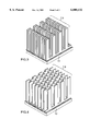
- FIG. 3 is a perspective view of a heat sink assembled from a plurality of heat sink fins, in accordance with the preferred embodiment.
- FIG. 4 is a perspective view of a heat sink assembled from a plurality of heat sink fins, in accordance with an alternative embodiment of the invention.
- a generally rectangular blank 1 of suitable heat conductive material e.g. aluminum
- suitable heat conductive material e.g. aluminum
- a crenellated scribe line 5 is shown in FIG. 1B along which the blank 1 is punched or sheared to provide two mirror-image heat sink fins 7 and 9, as shown in FIGS. 2A to 2D.
- Each heat sink fin 7 and 9 comprises a bell-bottom foot portion (foot portion 3' in the fin 7 (FIG. 2B) and foot portion 3 in the fin 9 (FIG. 2D)), and a plurality of tongues 11 which emulate the structure of prior art wire fins or pin fins.
- scribe line 5 is depicted to illustrate the pattern for the shearing or punching of blank 1, in practice no such line is required to be actually drawn on the blank 1.
- the shearing or punching step can be carried out using well known punch presses or shearing machines, the construction of which do not form part of the present invention.
- foot portions 3 and 3' are received within cooperatively shaped grooves of an extruded base plate 13 and subsequently swaged in accordance with the principles set forth in commonly-owned U.S. Pat. No. 5,406,698 (Lipinski) to form the heat sink structure of the preferred embodiment (FIG. 3) with aligned tongue portions 11, or the structure of an alternative embodiment (FIG. 4) wherein the tongues 11 are offset or staggered relative to one another.
- the heat sink structures of FIGS. 3 and 4, fabricated according to the method of the present invention, provide increased thermal performance and reduced weight characterized by prior art pin fin or wire fin heat sinks, relative to prior art rectangular fin heat sinks. Furthermore, by fabricating two fins 7 and 9 from a single blank 1, the heat sink of the present invention is less costly to produce and results in less waste material than prior art rectangular fin heat sinks, yet can be fabricated using the simplified swaging operation of U.S. Pat. No. 5,406,698 (Lipinski), the contents of which are incorporated herein by reference.
Landscapes
- Engineering & Computer Science (AREA)
- Physics & Mathematics (AREA)
- Condensed Matter Physics & Semiconductors (AREA)
- General Physics & Mathematics (AREA)
- Computer Hardware Design (AREA)
- Microelectronics & Electronic Packaging (AREA)
- Power Engineering (AREA)
- Manufacturing & Machinery (AREA)
- Mechanical Engineering (AREA)
- Chemical & Material Sciences (AREA)
- Materials Engineering (AREA)
- Cooling Or The Like Of Semiconductors Or Solid State Devices (AREA)
Abstract
Description
Claims (6)
Priority Applications (1)
| Application Number | Priority Date | Filing Date | Title |
|---|---|---|---|
| US08/980,592 US6000132A (en) | 1997-12-01 | 1997-12-01 | Method of forming heat dissipating fins |
Applications Claiming Priority (1)
| Application Number | Priority Date | Filing Date | Title |
|---|---|---|---|
| US08/980,592 US6000132A (en) | 1997-12-01 | 1997-12-01 | Method of forming heat dissipating fins |
Publications (1)
| Publication Number | Publication Date |
|---|---|
| US6000132A true US6000132A (en) | 1999-12-14 |
Family
ID=25527693
Family Applications (1)
| Application Number | Title | Priority Date | Filing Date |
|---|---|---|---|
| US08/980,592 Expired - Lifetime US6000132A (en) | 1997-12-01 | 1997-12-01 | Method of forming heat dissipating fins |
Country Status (1)
| Country | Link |
|---|---|
| US (1) | US6000132A (en) |
Cited By (19)
| Publication number | Priority date | Publication date | Assignee | Title |
|---|---|---|---|---|
| US6141219A (en) * | 1998-12-23 | 2000-10-31 | Sundstrand Corporation | Modular power electronics die having integrated cooling apparatus |
| US6201695B1 (en) * | 1998-10-26 | 2001-03-13 | Micron Technology, Inc. | Heat sink for chip stacking applications |
| US6202303B1 (en) * | 1999-04-08 | 2001-03-20 | Intel Corporation | Method for producing high efficiency heat sinks |
| US6370774B1 (en) * | 2000-07-21 | 2002-04-16 | Ling-Po Sheu | Radiator with thin fins and method for producing the same |
| US6446709B1 (en) * | 2001-11-27 | 2002-09-10 | Wuh Choung Industrial Co., Ltd. | Combination heat radiator |
| EP1328019A1 (en) * | 2002-01-10 | 2003-07-16 | Wen-Chen Wei | Leaf piece structure for heat dissipater |
| EP1328020A1 (en) * | 2002-01-10 | 2003-07-16 | Wen-Chen Wei | Fin piece structure for heat dissipater |
| US20050156013A1 (en) * | 2004-01-21 | 2005-07-21 | Bhatti Mohinder S. | Method of making high performance heat sinks |
| US20060090873A1 (en) * | 2004-11-01 | 2006-05-04 | Egbon Electronics Ltd. | Method for manufacturing heat sink devices |
| US20070044947A1 (en) * | 2005-08-25 | 2007-03-01 | Sgl Carbon Ag | Heat exchanger block |
| US20070137849A1 (en) * | 2005-12-15 | 2007-06-21 | Toshiba International Corporation | Heatsink with offset fins |
| KR100866389B1 (en) * | 2002-04-29 | 2008-10-31 | 주식회사 아이메탈아이 | Heat Sink and Method For Making The Same |
| WO2009128462A1 (en) * | 2008-04-16 | 2009-10-22 | Toyota Jidosha Kabushiki Kaisha | Method of manufacturing a heat exchanger |
| US20100065248A1 (en) * | 2008-09-17 | 2010-03-18 | Asia Vital Components Co., Ltd. | Heat sink |
| US20100079950A1 (en) * | 2008-10-01 | 2010-04-01 | Asia Vital Components (Shen Zhen) Co., Ltd. | Radiating Fin and Thermal Module Formed Therefrom |
| US8659042B2 (en) | 2010-12-21 | 2014-02-25 | Palo Alto Research Center Incorporated | Integrated reflector and thermal spreader and thermal spray fabrication method |
| US20140062227A1 (en) * | 2012-09-06 | 2014-03-06 | Siemens Industry, Inc. | Apparaus and method for induction motor heat transfer |
| US8695687B2 (en) | 2010-12-10 | 2014-04-15 | Palo Alto Research Center Incorporated | Hybrid pin-fin micro heat pipe heat sink and method of fabrication |
| US20230262937A1 (en) * | 2022-02-11 | 2023-08-17 | Quanta Computer Inc. | Combination heat sink |
Citations (12)
| Publication number | Priority date | Publication date | Assignee | Title |
|---|---|---|---|---|
| US4879891A (en) * | 1987-04-27 | 1989-11-14 | Thermalloy Incorporated | Method of manufacturing heat sink apparatus |
| US4884331A (en) * | 1987-04-27 | 1989-12-05 | Thermalloy Incorporated | Method of manufacturing heat sink apparatus |
| US5014776A (en) * | 1988-04-27 | 1991-05-14 | Joachim Hess | Heat emitting unit in form of a heater or cooler |
| JPH049644A (en) * | 1990-04-26 | 1992-01-14 | Yokogawa Electric Corp | Infrared moisture meter reducing influence of paper quality |
| US5351748A (en) * | 1993-01-21 | 1994-10-04 | Baruch Dagan | Tubular pin fin heat sink for electronic components |
| US5381859A (en) * | 1990-11-09 | 1995-01-17 | Kabushiki Kaisha Toshiba | Heat sink and the producing method thereof |
| US5406698A (en) * | 1993-10-06 | 1995-04-18 | R-Theta Inc. | Apparatus for fabricating high fin density heatsinks |
| US5419041A (en) * | 1992-08-04 | 1995-05-30 | Aqty Co., Ltd. | Process for manufacturing a pin type radiating fin |
| US5421406A (en) * | 1992-06-16 | 1995-06-06 | Showa Aluminum Corporation | Heat sinks having pin-shaped fins and process for producing same |
| US5499450A (en) * | 1994-12-19 | 1996-03-19 | Jacoby; John | Method of manufacturing a multiple pin heatsink device |
| US5542176A (en) * | 1992-09-21 | 1996-08-06 | Hideaki Serizawa | Radiation plate and method of producing the same |
| US5590712A (en) * | 1993-05-27 | 1997-01-07 | Redpoint Thermalloy, Ltd. | Heat sink |
-
1997
- 1997-12-01 US US08/980,592 patent/US6000132A/en not_active Expired - Lifetime
Patent Citations (13)
| Publication number | Priority date | Publication date | Assignee | Title |
|---|---|---|---|---|
| US4879891A (en) * | 1987-04-27 | 1989-11-14 | Thermalloy Incorporated | Method of manufacturing heat sink apparatus |
| US4884331A (en) * | 1987-04-27 | 1989-12-05 | Thermalloy Incorporated | Method of manufacturing heat sink apparatus |
| US4884331B1 (en) * | 1987-04-27 | 1994-05-03 | Thermalloy Inc | Method of manufacturing heat sink apparatus |
| US5014776A (en) * | 1988-04-27 | 1991-05-14 | Joachim Hess | Heat emitting unit in form of a heater or cooler |
| JPH049644A (en) * | 1990-04-26 | 1992-01-14 | Yokogawa Electric Corp | Infrared moisture meter reducing influence of paper quality |
| US5381859A (en) * | 1990-11-09 | 1995-01-17 | Kabushiki Kaisha Toshiba | Heat sink and the producing method thereof |
| US5421406A (en) * | 1992-06-16 | 1995-06-06 | Showa Aluminum Corporation | Heat sinks having pin-shaped fins and process for producing same |
| US5419041A (en) * | 1992-08-04 | 1995-05-30 | Aqty Co., Ltd. | Process for manufacturing a pin type radiating fin |
| US5542176A (en) * | 1992-09-21 | 1996-08-06 | Hideaki Serizawa | Radiation plate and method of producing the same |
| US5351748A (en) * | 1993-01-21 | 1994-10-04 | Baruch Dagan | Tubular pin fin heat sink for electronic components |
| US5590712A (en) * | 1993-05-27 | 1997-01-07 | Redpoint Thermalloy, Ltd. | Heat sink |
| US5406698A (en) * | 1993-10-06 | 1995-04-18 | R-Theta Inc. | Apparatus for fabricating high fin density heatsinks |
| US5499450A (en) * | 1994-12-19 | 1996-03-19 | Jacoby; John | Method of manufacturing a multiple pin heatsink device |
Cited By (30)
| Publication number | Priority date | Publication date | Assignee | Title |
|---|---|---|---|---|
| US6707673B2 (en) * | 1998-10-26 | 2004-03-16 | Micron Technology, Inc. | Heat sink for chip stacking applications |
| US6201695B1 (en) * | 1998-10-26 | 2001-03-13 | Micron Technology, Inc. | Heat sink for chip stacking applications |
| US6449161B2 (en) * | 1998-10-26 | 2002-09-10 | Micron Technology, Inc. | Heat sink for chip stacking applications |
| US6141219A (en) * | 1998-12-23 | 2000-10-31 | Sundstrand Corporation | Modular power electronics die having integrated cooling apparatus |
| US6202303B1 (en) * | 1999-04-08 | 2001-03-20 | Intel Corporation | Method for producing high efficiency heat sinks |
| US6374491B1 (en) | 1999-04-08 | 2002-04-23 | Intel Corporation | Method and apparatus for producing high efficiency heat sinks |
| US6539614B2 (en) | 1999-04-08 | 2003-04-01 | Intel Corporation | Apparatus for producing high efficiency heat sinks |
| US6370774B1 (en) * | 2000-07-21 | 2002-04-16 | Ling-Po Sheu | Radiator with thin fins and method for producing the same |
| US6446709B1 (en) * | 2001-11-27 | 2002-09-10 | Wuh Choung Industrial Co., Ltd. | Combination heat radiator |
| EP1328019A1 (en) * | 2002-01-10 | 2003-07-16 | Wen-Chen Wei | Leaf piece structure for heat dissipater |
| EP1328020A1 (en) * | 2002-01-10 | 2003-07-16 | Wen-Chen Wei | Fin piece structure for heat dissipater |
| KR100866389B1 (en) * | 2002-04-29 | 2008-10-31 | 주식회사 아이메탈아이 | Heat Sink and Method For Making The Same |
| US20050156013A1 (en) * | 2004-01-21 | 2005-07-21 | Bhatti Mohinder S. | Method of making high performance heat sinks |
| US7537151B2 (en) * | 2004-01-21 | 2009-05-26 | Delphi Technologies, Inc. | Method of making high performance heat sinks |
| US20060090873A1 (en) * | 2004-11-01 | 2006-05-04 | Egbon Electronics Ltd. | Method for manufacturing heat sink devices |
| US20070044947A1 (en) * | 2005-08-25 | 2007-03-01 | Sgl Carbon Ag | Heat exchanger block |
| US7549464B2 (en) * | 2005-08-25 | 2009-06-23 | Sgl Carbon Ag | Heat exchanger block |
| US20070137849A1 (en) * | 2005-12-15 | 2007-06-21 | Toshiba International Corporation | Heatsink with offset fins |
| WO2009128462A1 (en) * | 2008-04-16 | 2009-10-22 | Toyota Jidosha Kabushiki Kaisha | Method of manufacturing a heat exchanger |
| US20110030217A1 (en) * | 2008-04-16 | 2011-02-10 | Toyota Jidosha Kabushiki Kaisha | Method of manufacturing a heat exchanger |
| US8844134B2 (en) * | 2008-04-16 | 2014-09-30 | Toyota Jidosha Kabushiki Kaisha | Method of manufacturing a heat exchanger |
| US20100065248A1 (en) * | 2008-09-17 | 2010-03-18 | Asia Vital Components Co., Ltd. | Heat sink |
| US20100079950A1 (en) * | 2008-10-01 | 2010-04-01 | Asia Vital Components (Shen Zhen) Co., Ltd. | Radiating Fin and Thermal Module Formed Therefrom |
| US8695687B2 (en) | 2010-12-10 | 2014-04-15 | Palo Alto Research Center Incorporated | Hybrid pin-fin micro heat pipe heat sink and method of fabrication |
| US8659042B2 (en) | 2010-12-21 | 2014-02-25 | Palo Alto Research Center Incorporated | Integrated reflector and thermal spreader and thermal spray fabrication method |
| US8936954B2 (en) | 2010-12-21 | 2015-01-20 | Palo Alto Research Center Incorporated | Integrated reflector and thermal spreader and thermal spray fabrication method |
| US20140062227A1 (en) * | 2012-09-06 | 2014-03-06 | Siemens Industry, Inc. | Apparaus and method for induction motor heat transfer |
| US9520755B2 (en) * | 2012-09-06 | 2016-12-13 | Siemens Industry, Inc. | Apparatus and method for induction motor heat transfer |
| US20230262937A1 (en) * | 2022-02-11 | 2023-08-17 | Quanta Computer Inc. | Combination heat sink |
| US12052846B2 (en) * | 2022-02-11 | 2024-07-30 | Quanta Computer Inc. | Combination heat sink |
Similar Documents
| Publication | Publication Date | Title |
|---|---|---|
| US6000132A (en) | Method of forming heat dissipating fins | |
| KR100294873B1 (en) | LS Eye Package Cooling Wave Heat Sink Assembly | |
| US6321451B1 (en) | Method for making a heat sink | |
| US6827130B2 (en) | Heatsink assembly and method of manufacturing the same | |
| US5761811A (en) | Assembling method for cooling apparatus | |
| US6450250B2 (en) | Stackable heat sink for electronic components | |
| EP1172852B1 (en) | Corrugated matrix heat sink for cooling electronic components | |
| EP0485205B1 (en) | Heat sink and the producing method thereof | |
| US5419041A (en) | Process for manufacturing a pin type radiating fin | |
| WO1987000913A1 (en) | Heat sink formed of stacked fin elements | |
| US6199627B1 (en) | Heat sink | |
| US6088917A (en) | Method for making heat sink device and a heat sink made thereby | |
| KR100882581B1 (en) | Cooler for computer parts and manufacturing method of the cooler | |
| JP4383532B2 (en) | Method of forming a radiator | |
| JPH0581336B2 (en) | ||
| JPS6123349A (en) | Radiator | |
| KR19990014818A (en) | Heat sink and assembly method | |
| JP3786868B2 (en) | Heat sink and method of manufacturing heat sink | |
| JPH11238837A (en) | Heat radiating fin and its manufacture | |
| JPH09283666A (en) | Heat sink and manufacture | |
| WO1996036995A1 (en) | A heatsink and a method and an assembly for forming the same | |
| JP3928099B2 (en) | Heat sink and manufacturing method thereof | |
| JP3434552B2 (en) | heatsink | |
| JPH05166982A (en) | Radiator | |
| KR200392785Y1 (en) | Skived-fin annular heat sink |
Legal Events
| Date | Code | Title | Description |
|---|---|---|---|
| AS | Assignment |
Owner name: R-THETA INC., CANADA Free format text: ASSIGNMENT OF ASSIGNORS INTEREST;ASSIGNOR:BUTLER, JAMES R.S.;REEL/FRAME:009567/0509 Effective date: 19971020 |
|
| STCF | Information on status: patent grant |
Free format text: PATENTED CASE |
|
| REMI | Maintenance fee reminder mailed | ||
| FPAY | Fee payment |
Year of fee payment: 4 |
|
| SULP | Surcharge for late payment | ||
| FPAY | Fee payment |
Year of fee payment: 8 |
|
| AS | Assignment |
Owner name: R-THETA THERMAL SOLUTIONS INC., CANADA Free format text: ASSIGNMENT OF ASSIGNORS INTEREST;ASSIGNOR:R-THETA INC.;REEL/FRAME:020617/0622 Effective date: 20080205 |
|
| FEPP | Fee payment procedure |
Free format text: PAT HOLDER NO LONGER CLAIMS SMALL ENTITY STATUS, ENTITY STATUS SET TO UNDISCOUNTED (ORIGINAL EVENT CODE: STOL); ENTITY STATUS OF PATENT OWNER: LARGE ENTITY |
|
| FPAY | Fee payment |
Year of fee payment: 12 |