US5993245A - Terminal structure - Google Patents
Terminal structure Download PDFInfo
- Publication number
- US5993245A US5993245A US08/884,054 US88405497A US5993245A US 5993245 A US5993245 A US 5993245A US 88405497 A US88405497 A US 88405497A US 5993245 A US5993245 A US 5993245A
- Authority
- US
- United States
- Prior art keywords
- metal plate
- terminal
- metal
- electrically conductive
- case
- Prior art date
- Legal status (The legal status is an assumption and is not a legal conclusion. Google has not performed a legal analysis and makes no representation as to the accuracy of the status listed.)
- Expired - Fee Related
Links
- 239000002184 metal Substances 0.000 claims abstract description 142
- 229910052751 metal Inorganic materials 0.000 claims abstract description 142
- 230000006835 compression Effects 0.000 description 7
- 238000007906 compression Methods 0.000 description 7
- 229920003002 synthetic resin Polymers 0.000 description 6
- 239000000057 synthetic resin Substances 0.000 description 6
- 239000004020 conductor Substances 0.000 description 3
- XEEYBQQBJWHFJM-UHFFFAOYSA-N Iron Chemical compound [Fe] XEEYBQQBJWHFJM-UHFFFAOYSA-N 0.000 description 2
- 239000000463 material Substances 0.000 description 2
- 230000002159 abnormal effect Effects 0.000 description 1
- 230000007547 defect Effects 0.000 description 1
- 230000002349 favourable effect Effects 0.000 description 1
- 229910052742 iron Inorganic materials 0.000 description 1
- 238000000034 method Methods 0.000 description 1
- 238000005476 soldering Methods 0.000 description 1
Images


Classifications
-
- H—ELECTRICITY
- H01—ELECTRIC ELEMENTS
- H01R—ELECTRICALLY-CONDUCTIVE CONNECTIONS; STRUCTURAL ASSOCIATIONS OF A PLURALITY OF MUTUALLY-INSULATED ELECTRICAL CONNECTING ELEMENTS; COUPLING DEVICES; CURRENT COLLECTORS
- H01R4/00—Electrically-conductive connections between two or more conductive members in direct contact, i.e. touching one another; Means for effecting or maintaining such contact; Electrically-conductive connections having two or more spaced connecting locations for conductors and using contact members penetrating insulation
- H01R4/28—Clamped connections, spring connections
- H01R4/48—Clamped connections, spring connections utilising a spring, clip, or other resilient member
- H01R4/4809—Clamped connections, spring connections utilising a spring, clip, or other resilient member using a leaf spring to bias the conductor toward the busbar
- H01R4/4828—Spring-activating arrangements mounted on or integrally formed with the spring housing
- H01R4/48365—Spring-activating arrangements mounted on or integrally formed with the spring housing with integral release means
-
- H—ELECTRICITY
- H01—ELECTRIC ELEMENTS
- H01R—ELECTRICALLY-CONDUCTIVE CONNECTIONS; STRUCTURAL ASSOCIATIONS OF A PLURALITY OF MUTUALLY-INSULATED ELECTRICAL CONNECTING ELEMENTS; COUPLING DEVICES; CURRENT COLLECTORS
- H01R4/00—Electrically-conductive connections between two or more conductive members in direct contact, i.e. touching one another; Means for effecting or maintaining such contact; Electrically-conductive connections having two or more spaced connecting locations for conductors and using contact members penetrating insulation
- H01R4/28—Clamped connections, spring connections
- H01R4/48—Clamped connections, spring connections utilising a spring, clip, or other resilient member
- H01R4/4854—Clamped connections, spring connections utilising a spring, clip, or other resilient member using a wire spring
- H01R4/4863—Coil spring
Definitions
- the present invention relates to a terminal structure, and, more particularly, relates to a specific terminal structure, wherein a metal plate is turned away from a metal terminal against the spring action of a torsion coil spring while an electrically conductive wire is inserted. If the action is applied to the electrically conductive wire to be pulled out from the structure, the metal plate is turned towards the metal terminal thereby to press the electrically conductive wire against the metal terminal with a stronger force and secure the electric conduction between the metal terminal and the wire.
- the torsion coil spring of a specific elasticity normally gives such pressure as to hold the electrically conductive wire and the metal terminal in an electrically stabilized conductive condition. Further the electrically conductive wire may be attached and detached with one-touch light operating action.
- the terminal structure 1 shown in FIG. 15 is composed of an electrically isolated case 2 of synthetic resin.
- the terminal structure has a metal terminal 3 secured to and within the case 2 by a pair of extensions 3a being protruded out of the case.
- a metal plate 4 that is, a substantially U-shaped plate spring, has a center portion 4a mounted on a pin 2a formed on the case 2, has one end 4b engaging an inner surface 2b, and has the opposite end 4c pressed against the metal terminal 3.
- an operating pin 5 is slidably inserted into a guide hole 2c formed within the case 2.
- the inner end 5a of the operating pin 5 presses the end 4c of the metal plate 4 against the spring action thereof in the direction away from the terminal 3.
- the electrically conductive wire (not shown) may be inserted into between the metal terminal 3 and the metal plate 4 through a wire guide hole 2d formed within the case 2.
- the metal plate 4 Upon freeing the operating pin 5, the metal plate 4 returns with its elasticity to press the electrically conductive wire against the metal plate 3, thereby to secure the electric conduction between the electrically conductive wire and the metal plate 3.
- the user is required to press such a small operating pin 5 against the strong spring action of the plate spring in order to insert the electrically conductive wire into the structure 1 or to pull out the same therefrom. Therefore the operation of the operating pin 5 will cause pain to the finger of the user and the operability is extremely bad. As the result, the user often fails to press the operating pin 5 deep enough allowing the electrically conductive wire to be forcibly pulled out of the case with the resultant damages given to the terminal structure 1.
- FIG. 16 Another conventional terminal structure 10, as shown in FIG. 16, is composed of an electrically isolated case 11 of synthetic resin.
- the terminal structure has a U-shaped metal terminal 12 secured to and within the case 11 by a pair of extensions protruded out of the case.
- a metal plate 13 has one end formed in a ring 13a and has an opposite flat end 13b.
- the metal plate 13 is, at the ring 13a, turnably mounted on a support pin 11a formed on the case 11 so that the metal plate 13 may be turnable with respect to the metal terminal 12.
- a compression coil spring 14 is provided between the case 11 and the metal plate 13 so that the compression coil spring 14 may press the flat end 13b of the metal plate 13 against the metal terminal 12. Further an operating pin 15 is slidably inserted into a guide hole 11b formed within the case 11.
- the conventional terminal structure 10 especially having the compression coil spring 14 used in such a way that one end of the compression coil spring 14 is simply pressed against the metal plate 13, the end of the compression coil spring 14 is actually liable to slide with respect to the metal plate 13. It therefore often happens that the position where the compression coil spring 14 applies the pressure to the metal plate 13 will change each time the operating pin 15 is pressingly operated. As the result, it becomes difficult to hold the electrically conductive wire with a constantly stabilized pressure.
- the invention has been provided to eliminate the defects and disadvantages of the prior art as mentioned above. It is therefore a primary object of the invention to provide a unique terminal structure substantially comprising a metal plate having one end turnably mounted on the case so that the metal plate may be turnable with respect to a metal terminal and a torsion coil spring having one end normally pressing the metal plate in the direction of the metal terminal so that the metal plate may press an electrically conductive wire against the metal terminal, thereby to establish the electric conduction between the metal terminal and the electrically conductive wire, wherein the metal plate maybe turned away from the metal terminal with a considerably light operating action and the electrically conductive wire may be easily and securely connected to the metal terminal, and further the terminal structure may be prevented from the damages which may otherwise be caused by abnormal pull of the wire from the terminal structure.
- the present invention relates to a terminal structure for detachably holding an electrically conductive wire for electrical conduction therewith, and is characterized by combination of a case, a metal terminal provided in the case, a metal plate provided in the case and having one end turnably mounted on the case so that the metal plate may be turnable with respect to the metal terminal, and a torsion coil spring having a coil portion turnably mounted on the case and having one end thereof engaging the metal plate and having the opposite end engaging the case.
- the torsion spring normally applies a pressure to the metal plate so that the metal plate may press the electrically conductive wire against the metal terminal to establish the electric conduction between the electrically conductive wire and the metal terminal, the torsion coil spring allowing the metal plate to be turned away from the metal terminal against the spring action of the torsion spring when the electrically conductive wire is inserted into the case, the torsion coil spring turning the metal plate towards the metal terminal when a force is applied to the electrically conductive wire to pull the same outwardly of the case, thereby to increase the pressure for holding the electrically conductive wire between the metal plate and the metal terminal.
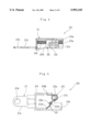
- FIGS. 1 through 9 show a first embodiment of the invention, wherein:
- FIG. 1 is a perspective view of a terminal structure
- FIG. 2 is an exploded perspective view of the terminal structure
- FIG. 3 is a plan elevational view of the terminal structure shown in lateral section
- FIG. 4 is a front elevational view of the terminal structure
- FIG. 5 is a perspective view of the terminal structure partly broken to show the essential part thereof;
- FIG. 6 is a perspective view of three pieces of terminal structures arranged side by side within a case shown partly broken;
- FIG. 7 is a front elevational view of the terminal structure shown in vertical section to show an electrically conductive wire being inserted into the terminal structure;
- FIG. 8 is a front elevational view of the terminal structure shown in vertical section to show the electrically conductive wire which is pressed against a metal terminal by a metal plate and is made electrically conductive with the metal terminal;
- FIG. 9 is a front elevational view of the terminal structure shown in vertical section to show the electrically conductive wire which is pulled out of the case;
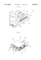
- FIGS. 10 through 14 show a second embodiment of the invention, wherein:
- FIG. 10 is a perspective view of a terminal structure broke to show the essential part thereof;
- FIG. 11 is a front elevational view of the terminal structure shown in vertical section
- FIG. 12 is a front elevational view of the terminal structure shown in vertical section to show an electrically conductor wire inserted into the terminal structure;
- FIG. 13 is a front elevational view of the terminal structure shown in vertical section to show the electrically conductor wire inserted deep into the terminal structure while a metal plate is turned away from a metal terminal;
- FIG. 14 is a front elevational view of the terminal structure shown in vertical section to show the electrically conductive wire pressed against the metal terminal by the metal plate and made electrically conductive with the metal terminal;
- FIGS. 15 and 16 show the conventional terminal structures, wherein:
- FIG. 15 is a front elevational view of a terminal structure shown in vertical section to show a metal plate formed as a plate spring;
- FIG. 16 is a front elevational view of another terminal structure shown in vertical section to show a metal plate pressed by a compression coil spring.
- a terminal structure 20 of the first embodiment according to the invention is substantially composed of a metal terminal 21, a metal plate 22 and a torsion coil spring 23.
- the metal terminal 21 is provided to take out the electric conduction through the terminal structure 20, and is formed with a plate of metal such as iron plated with an electrically favorable conductive material.
- the plate is, as shown, bent into a sidewise U-shape having opposite sidewalls 21d, 21f.
- the metal terminal 21 has an extension 21a provided on one side lengthwise of the side walls and having an opening 21b formed at the end thereof so that an electrically conductive wire (not shown) may be inserted therethrough and soldering the to the end. Further the metal terminal 21 has another extension of a reduced width provided opposite to the extension 21a and bent at right angle in the same direction with the side walls 21d, 21f so as to form a support pin 21c.
- the side wall 21d has an upper side providing a contact surface 21e, which is roughly processed with the knurling process so as to securely hold an electrically conductive wire 24 pressed thereagainst.
- the other side wall 21f has an opening 21g through which one end of the torsion coil spring 23 is inserted.
- the metal plate 22 is provided to press the electrically conductive wire 24 against the contact surface 21e of the metal terminal 21.
- the metal plate 22 has one end formed with rings 22a forked with a space 22c provided therebetween and has a slightly curved flat part extended from the forked rings 22a and forming a pressing part 22b.
- the flat part has a hole 22d formed thereon, into which the other end of the torsion coil spring 23 is inserted.
- the space 22c between the rings 22a is provided to accommodate therein a coil portion 23a of the torsion coil spring 23.
- the torsion coil spring 23 is provided to apply pressure to the metal plate 22.
- the opposite ends 23b, 23c of the spring are inserted into the opening 21g of the metal terminal 21 and into the hole 22d of the metal plate 22, respectively.
- a plurality of terminal structures 20, each of which is constructed as mentioned above, are contained in a case 25 of a material such as the synthetic resin and the like which is electrically isolated.
- the case 25 has an operating pin 26 slidably provided therein. The pin 26 may be pressed from the outside to apply pressure to the pressing part 22b of the metal plate 22 thereby to turn the metal plate 22 in the direction 2 where the metal plate 22 is spaced from the metal terminal 21.
- FIG. 6 shows three terminal structures 20 arranged side by side in the case 25 so that three electrically conductive wires 24 may be connected to the terminal structures 20, respectively.
- a terminal structure 30 is composed of a case 31 of a material such as the synthetic resin and the like, which is electrically isolated and a metal terminal 32 bent into a sidewise U-shape having a pair of spaced extensions 32a.
- the metal terminal 32 is secured to the case 31 with the spaced extensions 32a protruded from the case 31.
- the case 31 has a pin 31a and another pin 31b provided thereon at the positions respectively laterally spaced from the metal terminal 32. Further the case 31 has an abutment 31c formed thereon for engaging one end 33b of a torsion coil spring 33 and has a hole 31d and another hole 31e formed thereon.
- the hole 31d is provided to have an operating pin 34 to be inserted therethrough so that the operating pin 34 may be slidably movable therein, and the hole 31e is provided to have an electrically conductive wire 36 to be inserted therethrough.
- a metal plate 35 has a ring 35a formed at one end thereof and has a flat part slightly curved and extended from the ring 35a to form a pressing part 35b.
- the flat part of the metal plate 35 has a recess 35c formed thereon for engaging the other end 33c of the torsion coil spring 33.
- the ring 35a of the metal plate 35 is turnably mounted on the pin 31a of the case 31 so that the pressing part 35b may be pressed against the metal terminal 32.
- the torsion coil spring 33 has a coil portion 33a turnably mounted on the pin 31b of the case 31, and has one end 33b engaging the abutment 31c of the case 31 and the other end 33c engaging the recess 35c of the metal plate 35, so that the metal plate 35 may be normally pressed against the metal terminal 32.
- the present invention is structured as mentioned above and operates in the following manner.
- the electrically conductive wire 24 in order to connect the electrically conductive wire 24 to the terminal structure 20, the electrically conductive wire 24 is inserted into the hole 25a of the case 25 while the operating pin 26 is pressed in the direction as indicated by the arrow A.
- the metal plate 22 With the pressing operation of the operating pin 26, the metal plate 22 is, turned around the support pin 21c in the direction as indicated by the arrow C against the spring action of the torsion coil spring 23. The metal plate 22 is therefore moved away from the contact surface 21e of the metal terminal 21 while the electrically conductive wire 24 is inserted deep into the case 25.
- the metal plate 22 is turned by the spring action of the torsion spring 23 in the direction opposite to the direction indicated by the arrow C.
- the metal plate 22 will press the electrically conductive wire 24 against the contact surface 21e of the metal terminal 21, thereby to establish an electrically conductive relation between the metal terminal 21 and the electrically conductive wire 24.
- the operating pin 26 is returned in the direction as indicated by the arrow D to the initial inoperative position by the action of the spring action of the torsion coil spring 23.
- the operating pin 26 is, as shown in FIG. 9, is again pressed in the direction as indicated by the arrow A, thereby to turn the metal plate 22 around the support pin 21c in the direction as indicated by the arrow C against the spring action of the torsion spring 23.
- the electrically conductive wire 24 may be pulled out of the terminal structure 20 in the direction as indicated by the arrow E with an extremely light operation force of the operating pin 26.
- the torsion coil spring may, due to the property thereof, be initially set to have a small spring force. Precisely, concerning the torsion coil spring, the increasing amount of spring force (spring constant) per unit deformation amount may be set to a considerably small value compared with the plate spring.
- the operating pin 34 is pressed in the direction as indicated by the arrow F, thereby to turn the metal plate 35 around the support pin 31a away from the metal terminal 32 in the direction, as indicated by the arrow G, against the spring action especially of the end 33c of the torsion coil spring 33 while the electrically conductive wire 36 is inserted deep into the terminal structure 30 in the direction as indicated by the arrow I through the hole 31e.
- the operating pin 34 is pressed again in the direction as indicated by the arrow F, in the same manner as the first embodiment, thereby to turn the metal plate 35 away from the metal terminal 32 while the electrically conductive wire 36 is pulled out of the terminal structure 30.
Landscapes
- Connections Arranged To Contact A Plurality Of Conductors (AREA)
Applications Claiming Priority (2)
| Application Number | Priority Date | Filing Date | Title |
|---|---|---|---|
| JP8-257619 | 1996-09-06 | ||
| JP8257619A JPH1083850A (ja) | 1996-09-06 | 1996-09-06 | 端子台 |
Publications (1)
| Publication Number | Publication Date |
|---|---|
| US5993245A true US5993245A (en) | 1999-11-30 |
Family
ID=17308781
Family Applications (1)
| Application Number | Title | Priority Date | Filing Date |
|---|---|---|---|
| US08/884,054 Expired - Fee Related US5993245A (en) | 1996-09-06 | 1997-06-27 | Terminal structure |
Country Status (4)
| Country | Link |
|---|---|
| US (1) | US5993245A (ja) |
| EP (1) | EP0831557B1 (ja) |
| JP (1) | JPH1083850A (ja) |
| DE (1) | DE69703332T2 (ja) |
Cited By (13)
| Publication number | Priority date | Publication date | Assignee | Title |
|---|---|---|---|---|
| US6336824B1 (en) * | 1999-11-17 | 2002-01-08 | Weidmüller Interface Gmbh & Co. | Screwless junction box connection |
| US6488527B2 (en) * | 2000-01-19 | 2002-12-03 | Heung-Sik Yoon | Terminal with link strip |
| US6695638B1 (en) * | 2001-05-11 | 2004-02-24 | Daniel N. David | Electrical wire connector device |
| US20050046302A1 (en) * | 2001-12-04 | 2005-03-03 | Toshio Suzuki | Small-sized motor, small-sized vibration motor, and portable information device |
| US7090530B1 (en) * | 2005-09-22 | 2006-08-15 | Dibble Howard A | Quick connect electrical box |
| US20090266144A1 (en) * | 2008-04-23 | 2009-10-29 | Rezachek Thomas M | Photoacoustic sensor |
| EP2523257A1 (de) * | 2011-05-13 | 2012-11-14 | Weidmüller Interface GmbH & Co. KG | Klemmeinheit und Anschlussvorrichtung mit einer solchen Klemmeinheit |
| CN106374240A (zh) * | 2016-09-21 | 2017-02-01 | 上海航天科工电器研究院有限公司 | 一种带扭簧的锁线端子 |
| US10276962B2 (en) * | 2015-10-28 | 2019-04-30 | Autonetworks Technologies, Ltd. | Terminal with a case, a coil spring compressed in the case, a conductive member sandwiched between the case and an end of the coil spring and a wire connected to the conductive member |
| US10418740B2 (en) * | 2016-03-24 | 2019-09-17 | Autonetworks Technologies, Ltd. | Terminal module |
| CN110829131A (zh) * | 2019-11-20 | 2020-02-21 | 上海航天科工电器研究院有限公司 | 一种线转线电连接器模块 |
| WO2021196183A1 (zh) * | 2020-04-03 | 2021-10-07 | 昆山代克智能科技有限公司 | 一种安全的智能机器人充电机构 |
| WO2023131582A1 (de) * | 2022-01-05 | 2023-07-13 | Phoenix Contact Gmbh & Co. Kg | Elektrische anschlussvorrichtung |
Families Citing this family (14)
| Publication number | Priority date | Publication date | Assignee | Title |
|---|---|---|---|---|
| JP3682824B2 (ja) * | 1998-03-31 | 2005-08-17 | 矢崎総業株式会社 | コネクタ |
| DE19817927C1 (de) * | 1998-04-17 | 1999-10-28 | Wago Verwaltungs Gmbh | Steckverbinder als Buchsen- oder Stiftteil und mit einem Federkraftklemmanschluß für elektr. Leiter |
| US6146187A (en) | 1998-11-25 | 2000-11-14 | Supplie & Co. Import/Export, Inc. | Screwless terminal block |
| JP2001267652A (ja) * | 2000-03-17 | 2001-09-28 | Tokin Corp | 圧電トランス装置 |
| FR2824960B1 (fr) * | 2001-05-15 | 2003-08-15 | Entrelec | Dispositif de raccordement a poussoir |
| DE10230368B4 (de) * | 2002-07-05 | 2004-09-30 | Amphenol-Tuchel Electronics Gmbh | Halteelement zum Halten eines Leiteranschlussteils eines elektrischen Leiters in einer Aufnahmekammer |
| DK176022B1 (da) * | 2003-03-07 | 2005-12-19 | Lindberg As | Apparat, fikstur samt fremgangsmåde til fiksering af brilleglas for uindfattede briller |
| DE202010009666U1 (de) * | 2010-06-30 | 2011-11-29 | Weidmüller Interface GmbH & Co. KG | Miniatur-Federklemme |
| DE202011000602U1 (de) * | 2011-03-16 | 2012-06-18 | Weidmüller Interface GmbH & Co. KG | Klemmvorrichtung und Anschlussvorrichtung |
| ITMI20131303A1 (it) * | 2013-08-01 | 2015-02-02 | Stelvio Kontek S P A | Connettore elettrico e relativo dispositivo di azionamento |
| PL2947718T3 (pl) | 2014-05-23 | 2018-06-29 | Berker Gmbh & Co. Kg | Zacisk przyłączeniowy dociskany sprężyną |
| TWI603554B (zh) * | 2014-12-31 | 2017-10-21 | Electrical connection terminals improved structure | |
| CN205141189U (zh) * | 2015-01-13 | 2016-04-06 | 进联电子科技(上海)有限公司 | 电联接端子结构 |
| CN109390709B (zh) * | 2018-11-29 | 2020-01-07 | 上海航天科工电器研究院有限公司 | 一种快速锁线机构 |
Citations (1)
| Publication number | Priority date | Publication date | Assignee | Title |
|---|---|---|---|---|
| US4243285A (en) * | 1978-12-26 | 1981-01-06 | Raytheon Company | Clamp-plug type connector |
Family Cites Families (2)
| Publication number | Priority date | Publication date | Assignee | Title |
|---|---|---|---|---|
| DE1213024B (de) * | 1961-09-08 | 1966-03-24 | Siemens Ag | Klemme fuer schraubenlosen Leiteranschluss |
| DE29500614U1 (de) * | 1995-01-04 | 1995-03-16 | Wago Verwaltungs Gmbh | Elektrische Klemme mit Betätigungsdrücker |
-
1996
- 1996-09-06 JP JP8257619A patent/JPH1083850A/ja active Pending
-
1997
- 1997-06-24 DE DE69703332T patent/DE69703332T2/de not_active Expired - Fee Related
- 1997-06-24 EP EP97304453A patent/EP0831557B1/en not_active Expired - Lifetime
- 1997-06-27 US US08/884,054 patent/US5993245A/en not_active Expired - Fee Related
Patent Citations (1)
| Publication number | Priority date | Publication date | Assignee | Title |
|---|---|---|---|---|
| US4243285A (en) * | 1978-12-26 | 1981-01-06 | Raytheon Company | Clamp-plug type connector |
Cited By (17)
| Publication number | Priority date | Publication date | Assignee | Title |
|---|---|---|---|---|
| US6336824B1 (en) * | 1999-11-17 | 2002-01-08 | Weidmüller Interface Gmbh & Co. | Screwless junction box connection |
| US6488527B2 (en) * | 2000-01-19 | 2002-12-03 | Heung-Sik Yoon | Terminal with link strip |
| US6695638B1 (en) * | 2001-05-11 | 2004-02-24 | Daniel N. David | Electrical wire connector device |
| US20050046302A1 (en) * | 2001-12-04 | 2005-03-03 | Toshio Suzuki | Small-sized motor, small-sized vibration motor, and portable information device |
| US7265465B2 (en) * | 2001-12-04 | 2007-09-04 | Namiki Seimitsu Houseki Kabushiki Kaisha | Small-sized motor, small-sized vibration motor, and portable information device |
| US7090530B1 (en) * | 2005-09-22 | 2006-08-15 | Dibble Howard A | Quick connect electrical box |
| US20090266144A1 (en) * | 2008-04-23 | 2009-10-29 | Rezachek Thomas M | Photoacoustic sensor |
| US7958771B2 (en) | 2008-04-23 | 2011-06-14 | Honeywell International Inc. | Photoacoustic sensor |
| EP2523257A1 (de) * | 2011-05-13 | 2012-11-14 | Weidmüller Interface GmbH & Co. KG | Klemmeinheit und Anschlussvorrichtung mit einer solchen Klemmeinheit |
| US10276962B2 (en) * | 2015-10-28 | 2019-04-30 | Autonetworks Technologies, Ltd. | Terminal with a case, a coil spring compressed in the case, a conductive member sandwiched between the case and an end of the coil spring and a wire connected to the conductive member |
| US10418740B2 (en) * | 2016-03-24 | 2019-09-17 | Autonetworks Technologies, Ltd. | Terminal module |
| CN106374240A (zh) * | 2016-09-21 | 2017-02-01 | 上海航天科工电器研究院有限公司 | 一种带扭簧的锁线端子 |
| CN106374240B (zh) * | 2016-09-21 | 2018-07-20 | 上海航天科工电器研究院有限公司 | 一种带扭簧的锁线端子 |
| CN110829131A (zh) * | 2019-11-20 | 2020-02-21 | 上海航天科工电器研究院有限公司 | 一种线转线电连接器模块 |
| CN110829131B (zh) * | 2019-11-20 | 2021-09-17 | 上海航天科工电器研究院有限公司 | 一种线转线电连接器模块 |
| WO2021196183A1 (zh) * | 2020-04-03 | 2021-10-07 | 昆山代克智能科技有限公司 | 一种安全的智能机器人充电机构 |
| WO2023131582A1 (de) * | 2022-01-05 | 2023-07-13 | Phoenix Contact Gmbh & Co. Kg | Elektrische anschlussvorrichtung |
Also Published As
| Publication number | Publication date |
|---|---|
| DE69703332D1 (de) | 2000-11-23 |
| EP0831557A1 (en) | 1998-03-25 |
| DE69703332T2 (de) | 2001-02-22 |
| JPH1083850A (ja) | 1998-03-31 |
| EP0831557B1 (en) | 2000-10-18 |
Similar Documents
| Publication | Publication Date | Title |
|---|---|---|
| US5993245A (en) | Terminal structure | |
| US10658766B2 (en) | Spring terminal for a conductor | |
| US6261120B1 (en) | Resilient contact for connecting electrical conductors | |
| JP3734139B2 (ja) | フラット回路体用コネクタ | |
| JP4321873B2 (ja) | 同軸電気コネクタ | |
| EP0703117B1 (en) | Electric connection casing | |
| US6238233B1 (en) | Connecting device for at least one non-bared conductor | |
| US5593313A (en) | Socket with a plug locking mechanism | |
| EP0393058A1 (en) | ELECTRICAL TERMINAL WITH RECEPTACLE. | |
| KR930000792Y1 (ko) | 코넥터 장치 | |
| JPS6335072B2 (ja) | ||
| GB1565758A (en) | Solderless electrical contact | |
| US3812453A (en) | Electric terminal connector | |
| JP3159973B1 (ja) | 端子・ばね一体型のクランプ端子 | |
| US5697813A (en) | Connection terminal | |
| JP3913230B2 (ja) | プッシュターミナル | |
| JP3468880B2 (ja) | 接続端子 | |
| CN215834730U (zh) | 前螺钉端子 | |
| JP2005129339A (ja) | 圧接コネクタ | |
| JPH08130041A (ja) | 端子装置 | |
| US7014489B2 (en) | Land grid array connector assembly | |
| US5895285A (en) | Press-contact type connector | |
| JP7403924B2 (ja) | 端子構造 | |
| US6210190B1 (en) | Compact flexible board connector | |
| JPH0896899A (ja) | 電気コネクタ |
Legal Events
| Date | Code | Title | Description |
|---|---|---|---|
| AS | Assignment |
Owner name: OSADA CO., LTD., JAPAN Free format text: ASSIGNMENT OF ASSIGNORS INTEREST;ASSIGNOR:OSADA, YUTAKA;REEL/FRAME:008666/0989 Effective date: 19970418 |
|
| FPAY | Fee payment |
Year of fee payment: 4 |
|
| REMI | Maintenance fee reminder mailed | ||
| LAPS | Lapse for failure to pay maintenance fees | ||
| STCH | Information on status: patent discontinuation |
Free format text: PATENT EXPIRED DUE TO NONPAYMENT OF MAINTENANCE FEES UNDER 37 CFR 1.362 |
|
| FP | Lapsed due to failure to pay maintenance fee |
Effective date: 20071130 |