US5983930A - Air supply valve - Google Patents
Air supply valve Download PDFInfo
- Publication number
- US5983930A US5983930A US08/793,503 US79350397A US5983930A US 5983930 A US5983930 A US 5983930A US 79350397 A US79350397 A US 79350397A US 5983930 A US5983930 A US 5983930A
- Authority
- US
- United States
- Prior art keywords
- flap
- weight
- axle
- channel
- throttle
- Prior art date
- Legal status (The legal status is an assumption and is not a legal conclusion. Google has not performed a legal analysis and makes no representation as to the accuracy of the status listed.)
- Expired - Lifetime
Links
Images

Classifications
-
- F—MECHANICAL ENGINEERING; LIGHTING; HEATING; WEAPONS; BLASTING
- F23—COMBUSTION APPARATUS; COMBUSTION PROCESSES
- F23L—SUPPLYING AIR OR NON-COMBUSTIBLE LIQUIDS OR GASES TO COMBUSTION APPARATUS IN GENERAL ; VALVES OR DAMPERS SPECIALLY ADAPTED FOR CONTROLLING AIR SUPPLY OR DRAUGHT IN COMBUSTION APPARATUS; INDUCING DRAUGHT IN COMBUSTION APPARATUS; TOPS FOR CHIMNEYS OR VENTILATING SHAFTS; TERMINALS FOR FLUES
- F23L3/00—Arrangements of valves or dampers before the fire
-
- F—MECHANICAL ENGINEERING; LIGHTING; HEATING; WEAPONS; BLASTING
- F16—ENGINEERING ELEMENTS AND UNITS; GENERAL MEASURES FOR PRODUCING AND MAINTAINING EFFECTIVE FUNCTIONING OF MACHINES OR INSTALLATIONS; THERMAL INSULATION IN GENERAL
- F16K—VALVES; TAPS; COCKS; ACTUATING-FLOATS; DEVICES FOR VENTING OR AERATING
- F16K1/00—Lift valves or globe valves, i.e. cut-off apparatus with closure members having at least a component of their opening and closing motion perpendicular to the closing faces
- F16K1/16—Lift valves or globe valves, i.e. cut-off apparatus with closure members having at least a component of their opening and closing motion perpendicular to the closing faces with pivoted closure-members
- F16K1/18—Lift valves or globe valves, i.e. cut-off apparatus with closure members having at least a component of their opening and closing motion perpendicular to the closing faces with pivoted closure-members with pivoted discs or flaps
- F16K1/20—Lift valves or globe valves, i.e. cut-off apparatus with closure members having at least a component of their opening and closing motion perpendicular to the closing faces with pivoted closure-members with pivoted discs or flaps with axis of rotation arranged externally of valve member
-
- F—MECHANICAL ENGINEERING; LIGHTING; HEATING; WEAPONS; BLASTING
- F16—ENGINEERING ELEMENTS AND UNITS; GENERAL MEASURES FOR PRODUCING AND MAINTAINING EFFECTIVE FUNCTIONING OF MACHINES OR INSTALLATIONS; THERMAL INSULATION IN GENERAL
- F16K—VALVES; TAPS; COCKS; ACTUATING-FLOATS; DEVICES FOR VENTING OR AERATING
- F16K17/00—Safety valves; Equalising valves, e.g. pressure relief valves
- F16K17/02—Safety valves; Equalising valves, e.g. pressure relief valves opening on surplus pressure on one side; closing on insufficient pressure on one side
- F16K17/12—Safety valves; Equalising valves, e.g. pressure relief valves opening on surplus pressure on one side; closing on insufficient pressure on one side weight-loaded
-
- F—MECHANICAL ENGINEERING; LIGHTING; HEATING; WEAPONS; BLASTING
- F23—COMBUSTION APPARATUS; COMBUSTION PROCESSES
- F23L—SUPPLYING AIR OR NON-COMBUSTIBLE LIQUIDS OR GASES TO COMBUSTION APPARATUS IN GENERAL ; VALVES OR DAMPERS SPECIALLY ADAPTED FOR CONTROLLING AIR SUPPLY OR DRAUGHT IN COMBUSTION APPARATUS; INDUCING DRAUGHT IN COMBUSTION APPARATUS; TOPS FOR CHIMNEYS OR VENTILATING SHAFTS; TERMINALS FOR FLUES
- F23L13/00—Construction of valves or dampers for controlling air supply or draught
- F23L13/02—Construction of valves or dampers for controlling air supply or draught pivoted about a single axis but having not other movement
-
- Y—GENERAL TAGGING OF NEW TECHNOLOGICAL DEVELOPMENTS; GENERAL TAGGING OF CROSS-SECTIONAL TECHNOLOGIES SPANNING OVER SEVERAL SECTIONS OF THE IPC; TECHNICAL SUBJECTS COVERED BY FORMER USPC CROSS-REFERENCE ART COLLECTIONS [XRACs] AND DIGESTS
- Y10—TECHNICAL SUBJECTS COVERED BY FORMER USPC
- Y10T—TECHNICAL SUBJECTS COVERED BY FORMER US CLASSIFICATION
- Y10T137/00—Fluid handling
- Y10T137/0318—Processes
-
- Y—GENERAL TAGGING OF NEW TECHNOLOGICAL DEVELOPMENTS; GENERAL TAGGING OF CROSS-SECTIONAL TECHNOLOGIES SPANNING OVER SEVERAL SECTIONS OF THE IPC; TECHNICAL SUBJECTS COVERED BY FORMER USPC CROSS-REFERENCE ART COLLECTIONS [XRACs] AND DIGESTS
- Y10—TECHNICAL SUBJECTS COVERED BY FORMER USPC
- Y10T—TECHNICAL SUBJECTS COVERED BY FORMER US CLASSIFICATION
- Y10T137/00—Fluid handling
- Y10T137/7722—Line condition change responsive valves
- Y10T137/7837—Direct response valves [i.e., check valve type]
- Y10T137/7898—Pivoted valves
- Y10T137/7903—Weight biased
Definitions
- the present invention relates to a throttle device for delivery of a current of gas through a channel, the device comprising a flap which is arranged so that it can pivot on an axle and which is designed in such a way that, at a certain pressure force exerted by the current of gas, it is opened from a position in which the channel is essentially closed.
- air nozzles of various types are normally used, which air nozzles can consist of flaps which are opened by the pressure force exerted by the current of air.
- a throttle device for a heating boiler is already known from the document EP 0,022,599, which throttle device comprises a valve flap whose degree of opening can be set with the aid of an adjustable stop screw. This prevents draught from occurring when air is not flowing into the heating boiler.
- a throttle device for a heating boiler is also already known from FR 1,033,033, which throttle device comprises adjusting members for setting the degree of closure of a pivotably mounted valve flap.
- a principal object of the present invention is therefore to solve the abovementioned problems and to provide a throttle device with improved air penetration, that is to say with an increased degree of penetration of air which is flowing into the boiler, at the same time as the necessary pressure change for the combustion air is minimized.
- This is achieved by means of a device of the type mentioned in the introduction, which device is characterized in that it comprises at least one weight which is arranged to rotate together with the flap and is designed to deliver a torque to the axle in conjunction with the pivoting of the flap.
- the invention affords the possibility of opening different air nozzles at different air pressures in order to alter the flow pattern in the boiler without recourse to a complicated control system.
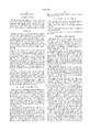
- FIG. 1 is a side view of the device according to the present invention
- FIG. 2 is a perspective view of an alternative embodiment of the invention.
- FIG. 3 is a diagrammatic view of another embodiment of the invention.
- FIG. 1 shows a throttle device in the form of an air nozzle in accordance with the present invention, which device is arranged in a channel 1 for delivery of air to an inlet 2 of a furnace.
- the furnace is part of a boiler which is not shown in any detail and which may be a recovery boiler or a bark boiler.
- the air flows through the channel 1 in the direction which is indicated by the arrow 3.
- the channel 1 consists of a pipe which preferably has a rectangular cross section, although some other form of cross section, for example square, is of course also conceivable.
- a valve flap 4 Arranged inside the channel 1 there is a valve flap 4, by means of which the channel 1 can be gradually closed or opened.
- the valve flap 4 consists of a plate which is designed in such a way that its external dimensions essentially correspond to the internal dimensions of the channel 1, except that the length of the flap is normally greater than the height of the channel 1.
- the flap 4 is pivotably suspended on an axle 5 which is arranged essentially at right angles to the longitudinal direction of the channel 1.
- the axle 5 is secured in the two side walls of the channel 1 in such a way that it can rotate, and it protrudes some distance outside the channel 1 on at least one side thereof.
- a lever arm 6 is arranged on that part of the axle 5 protruding outside the channel 1.
- the lever arm 6 is provided with a coupling piece which is fixed in terms of rotation on the axle 5.
- the position of the weight 7 is adjusted with the aid of an adjusting mechanism (not shown) which can comprise a screw, for example, with the aid of which the weight 7 can be screwed tight against the lever arm 6 when the latter is located in the desired position.
- the throttle device When the throttle device is located in its rest position, that is to say when the air pressure in the channel 1 is below the opening pressure which is defined by the weight 7 or the weight load on the flap 4, the gravity of the flap 4 results in a torque which acts in the counter-clockwise direction around the axle 5. This results in the flap 4 coming to bear (almost sealingly) against the bottom side of the channel 1. In its closed position, the flap 4 forms an angle of preferably 30° to 70° in relation to the longitudinal direction of the channel 1. When a certain air pressure is present in the air current in the channel 1, a pressure force is created which acts on the flap 4, and this gives rise to a certain torque. This leads to the flap 4 pivoting clock-wise.
- the weight 7 (which is connected to the axle 5 so that it is fixed in terms of rotation) also pivots clockwise. This gives rise to a certain additional torque which acts clockwise, that is to say which, together with the pressure force of the air current, has the effect of opening the flap 4.
- the weight 7 is thus arranged to be rotated together with the axle 5 and to deliver a torque to the axle 5 in conjunction with the pivoting of the flap 4, so that the weight 7 counteracts the dead weight of the flap 4.
- the mass of the flap 4 and the mass of the weight 7 are adapted to each other and to the air pressure prevailing in the channel 1 in such a way that the flap 4 and the weight 7 virtually counterbalance each other when the flap 4 is fully open.
- the mass of the flap 4 and the mass of the weight 7 must be adapted so that when the pressure of the air decreases or completely disappears, the torque from the flap 4 overcomes the torque from the weight 7 so that the flap 4 can again be closed.
- the position of the weight 7 in relation to the axle 5, and consequently the torque of the weight 7 around the axle 5, can be adapted to different air pressures in the current of air.
- the weight 7 is arranged outside the channel 1, it is also easy to gain access to it for purposes of adjustment.
- the lever arm 6 can alternatively be arranged such that in the rest position (that is to say when the flap 4 is in its lowered position) it deviates from the vertical as shown in FIG. 1.
- the lever arm 6 can be arranged, for example, in such a way that when the flap 4 is in its rest position, the lever arm produces a torque around the axle 5 which acts in the same direction as the torque which occurs as a result of the pressure force of the air. In this way, a relatively small pressure force of the air current is needed to open the flap 4.
- the lever arm 6 can also be arranged so that when the flap 4 is in its rest position, the lever arm contributes to the torque acting against the torque from the air current.
- FIG. 2 shows an alternative embodiment of the invention, which comprises a valve flap 4' which, in analogy with what has been stated above, is pivotably suspended on an axle 5' in a channel 1'.
- a lever arm 6' Fixed on the flap 4' there is a lever arm 6' on which a second weight 7' is arranged externally, which second weight 7' can preferably be displaced along the lever arm 6' in the radial direction in relation to the axle 5'.
- the second weight 7' and the lever arm 6' which are preferably placed outside the channel 1', are arranged in such a way that the second weight 7' cooperates with the weight of the flap 4' (that is to say so that the flap 4' is caused to close). In this way, the second weight 7' has the effect of increasing the counter-pressure against the current of air before the flap 4' is opened.
- FIG. 3 shows a diagrammatic representation of a further embodiment of the invention.
- the flap 4 is acted upon by two weights 7, 7' which are arranged on two lever arms 6, 6'.
- the device is otherwise constructed in analogy with what has been described above.
- the one lever arm 6' can be arranged on the axle 5 in such a way that the one weight 7' and its direction out from the axle 5 correspond to the resultant of what is provided in each position by a weight acting with the flap (that is to say the weight 7'), and a weight acting progressively against the flap.
- the invention is not limited to the embodiments which have been mentioned, but can be varied within the scope of the patent claims which follow.
- the invention functions for gases other than air which are suitable for different throttle devices where a high degree of penetration of the gas is sought.
- a plurality of weights can be provided for the flap, either on the lever arm or on the flap itself.
Landscapes
- Engineering & Computer Science (AREA)
- General Engineering & Computer Science (AREA)
- Mechanical Engineering (AREA)
- Chemical & Material Sciences (AREA)
- Combustion & Propulsion (AREA)
- Lift Valve (AREA)
- Percussion Or Vibration Massage (AREA)
- Fluid-Driven Valves (AREA)
- Engine Equipment That Uses Special Cycles (AREA)
- Compressor (AREA)
- Control Of The Air-Fuel Ratio Of Carburetors (AREA)
- Quick-Acting Or Multi-Walled Pipe Joints (AREA)
- Air-Flow Control Members (AREA)
- Regulation And Control Of Combustion (AREA)
Applications Claiming Priority (3)
| Application Number | Priority Date | Filing Date | Title |
|---|---|---|---|
| SE9402922 | 1994-09-01 | ||
| SE9402922A SE503950C2 (sv) | 1994-09-01 | 1994-09-01 | Spjällanordning |
| PCT/SE1995/000968 WO1996007055A1 (en) | 1994-09-01 | 1995-08-29 | Air supply valve |
Publications (1)
| Publication Number | Publication Date |
|---|---|
| US5983930A true US5983930A (en) | 1999-11-16 |
Family
ID=20395100
Family Applications (1)
| Application Number | Title | Priority Date | Filing Date |
|---|---|---|---|
| US08/793,503 Expired - Lifetime US5983930A (en) | 1994-09-01 | 1995-08-29 | Air supply valve |
Country Status (10)
| Country | Link |
|---|---|
| US (1) | US5983930A (de) |
| EP (1) | EP0777839B1 (de) |
| AT (1) | ATE185413T1 (de) |
| BR (1) | BR9508685A (de) |
| CA (1) | CA2198459A1 (de) |
| DE (1) | DE69512672T2 (de) |
| ES (1) | ES2139237T3 (de) |
| FI (1) | FI116986B (de) |
| SE (1) | SE503950C2 (de) |
| WO (1) | WO1996007055A1 (de) |
Cited By (6)
| Publication number | Priority date | Publication date | Assignee | Title |
|---|---|---|---|---|
| US6085781A (en) * | 1997-10-23 | 2000-07-11 | Promat Air, S.A. | Valve with pivoting flap and installation equipped with the valve |
| US6672227B2 (en) * | 2000-02-18 | 2004-01-06 | Kvaerner Pulping Ab | Arrangement for cleaning, airflow control and pushing away melt in air ports of incineration boilers |
| WO2004020907A2 (de) * | 2002-08-13 | 2004-03-11 | Rational Ag | Brennersystem, insbesondere für ein gargerät und verfahren zum betrieb desselben |
| CN102032978A (zh) * | 2010-11-09 | 2011-04-27 | 浙江方正阀门制造有限公司 | 阀门高温型式实验装置 |
| US20130305967A1 (en) * | 2011-02-25 | 2013-11-21 | Hermen Enterprises Limited | Burner |
| US20140373826A1 (en) * | 2013-06-19 | 2014-12-25 | Anthony Cote | Passive Constant Pressure Hatch for Fresh Air Direct Fired Gas Heated Ventilation Systems |
Families Citing this family (1)
| Publication number | Priority date | Publication date | Assignee | Title |
|---|---|---|---|---|
| AT505521B1 (de) * | 2007-08-14 | 2009-11-15 | Winkler Peter | Vorrichtung zum verbrennen von festbrennstoffelementen |
Citations (11)
| Publication number | Priority date | Publication date | Assignee | Title |
|---|---|---|---|---|
| US718657A (en) * | 1902-08-04 | 1903-01-20 | Jacob Manneschmidt Jr | Air-inlet valve. |
| US1263830A (en) * | 1916-05-05 | 1918-04-23 | Benjamin W Wolf | Ventilator. |
| US1312711A (en) * | 1919-08-12 | Sewer-trap | ||
| US1793802A (en) * | 1928-03-26 | 1931-02-24 | Roy Page | Draft normalizer |
| US2186354A (en) * | 1938-02-03 | 1940-01-09 | Everett Rosenberg H | Draft control means |
| US2219629A (en) * | 1939-04-24 | 1940-10-29 | Clarence H Lewis | Vernier quadrant damper for automatic furnace controls |
| DE3104474A1 (de) * | 1981-02-09 | 1982-08-19 | Otto 8898 Schrobenhausen Eppinger | Luftklappe mit zwei gewichten zur verhinderung einer nachstroemung von frischluft durch den feuerraum in den kamin, bei ausgeschaltetem brenner zum einbau in die abgas- oder luftansaugleitung von oel- und gasfeuerstaetten |
| US4384672A (en) * | 1980-08-08 | 1983-05-24 | Luitpold Kutzner | Draft limiting device |
| US4494564A (en) * | 1983-03-11 | 1985-01-22 | Fuller Company | Flap valve |
| US5365975A (en) * | 1994-03-22 | 1994-11-22 | E. H. Price Ltd. | Constant air pressure unit for air handling system |
| US5383485A (en) * | 1993-12-13 | 1995-01-24 | Lai; Herman | Valve for three-way tubings |
Family Cites Families (1)
| Publication number | Priority date | Publication date | Assignee | Title |
|---|---|---|---|---|
| SE28917C1 (de) * | 1910-05-28 |
-
1994
- 1994-09-01 SE SE9402922A patent/SE503950C2/sv not_active IP Right Cessation
-
1995
- 1995-08-29 EP EP95930767A patent/EP0777839B1/de not_active Expired - Lifetime
- 1995-08-29 ES ES95930767T patent/ES2139237T3/es not_active Expired - Lifetime
- 1995-08-29 US US08/793,503 patent/US5983930A/en not_active Expired - Lifetime
- 1995-08-29 WO PCT/SE1995/000968 patent/WO1996007055A1/en active IP Right Grant
- 1995-08-29 DE DE69512672T patent/DE69512672T2/de not_active Expired - Lifetime
- 1995-08-29 BR BR9508685A patent/BR9508685A/pt not_active IP Right Cessation
- 1995-08-29 AT AT95930767T patent/ATE185413T1/de active
- 1995-08-29 CA CA002198459A patent/CA2198459A1/en not_active Abandoned
-
1997
- 1997-02-28 FI FI970881A patent/FI116986B/fi not_active IP Right Cessation
Patent Citations (11)
| Publication number | Priority date | Publication date | Assignee | Title |
|---|---|---|---|---|
| US1312711A (en) * | 1919-08-12 | Sewer-trap | ||
| US718657A (en) * | 1902-08-04 | 1903-01-20 | Jacob Manneschmidt Jr | Air-inlet valve. |
| US1263830A (en) * | 1916-05-05 | 1918-04-23 | Benjamin W Wolf | Ventilator. |
| US1793802A (en) * | 1928-03-26 | 1931-02-24 | Roy Page | Draft normalizer |
| US2186354A (en) * | 1938-02-03 | 1940-01-09 | Everett Rosenberg H | Draft control means |
| US2219629A (en) * | 1939-04-24 | 1940-10-29 | Clarence H Lewis | Vernier quadrant damper for automatic furnace controls |
| US4384672A (en) * | 1980-08-08 | 1983-05-24 | Luitpold Kutzner | Draft limiting device |
| DE3104474A1 (de) * | 1981-02-09 | 1982-08-19 | Otto 8898 Schrobenhausen Eppinger | Luftklappe mit zwei gewichten zur verhinderung einer nachstroemung von frischluft durch den feuerraum in den kamin, bei ausgeschaltetem brenner zum einbau in die abgas- oder luftansaugleitung von oel- und gasfeuerstaetten |
| US4494564A (en) * | 1983-03-11 | 1985-01-22 | Fuller Company | Flap valve |
| US5383485A (en) * | 1993-12-13 | 1995-01-24 | Lai; Herman | Valve for three-way tubings |
| US5365975A (en) * | 1994-03-22 | 1994-11-22 | E. H. Price Ltd. | Constant air pressure unit for air handling system |
Cited By (9)
| Publication number | Priority date | Publication date | Assignee | Title |
|---|---|---|---|---|
| US6085781A (en) * | 1997-10-23 | 2000-07-11 | Promat Air, S.A. | Valve with pivoting flap and installation equipped with the valve |
| US6672227B2 (en) * | 2000-02-18 | 2004-01-06 | Kvaerner Pulping Ab | Arrangement for cleaning, airflow control and pushing away melt in air ports of incineration boilers |
| WO2004020907A2 (de) * | 2002-08-13 | 2004-03-11 | Rational Ag | Brennersystem, insbesondere für ein gargerät und verfahren zum betrieb desselben |
| WO2004020907A3 (de) * | 2002-08-13 | 2004-04-29 | Rational Ag | Brennersystem, insbesondere für ein gargerät und verfahren zum betrieb desselben |
| CN102032978A (zh) * | 2010-11-09 | 2011-04-27 | 浙江方正阀门制造有限公司 | 阀门高温型式实验装置 |
| CN102032978B (zh) * | 2010-11-09 | 2012-05-02 | 浙江方正阀门制造有限公司 | 阀门高温型式实验装置 |
| US20130305967A1 (en) * | 2011-02-25 | 2013-11-21 | Hermen Enterprises Limited | Burner |
| US20140373826A1 (en) * | 2013-06-19 | 2014-12-25 | Anthony Cote | Passive Constant Pressure Hatch for Fresh Air Direct Fired Gas Heated Ventilation Systems |
| US9562698B2 (en) * | 2013-06-19 | 2017-02-07 | Anthony Cote | Passive constant pressure hatch for fresh air direct fired gas heated ventilation systems |
Also Published As
| Publication number | Publication date |
|---|---|
| CA2198459A1 (en) | 1996-03-07 |
| EP0777839B1 (de) | 1999-10-06 |
| DE69512672T2 (de) | 2000-06-08 |
| DE69512672D1 (de) | 1999-11-11 |
| BR9508685A (pt) | 1998-05-26 |
| SE9402922D0 (sv) | 1994-09-01 |
| FI970881A (fi) | 1997-02-28 |
| ES2139237T3 (es) | 2000-02-01 |
| WO1996007055A1 (en) | 1996-03-07 |
| EP0777839A1 (de) | 1997-06-11 |
| SE503950C2 (sv) | 1996-10-07 |
| SE9402922L (sv) | 1996-03-02 |
| FI116986B (fi) | 2006-04-28 |
| ATE185413T1 (de) | 1999-10-15 |
| FI970881A0 (fi) | 1997-02-28 |
Similar Documents
| Publication | Publication Date | Title |
|---|---|---|
| FI71983C (fi) | Ventil. | |
| US5983930A (en) | Air supply valve | |
| US4384672A (en) | Draft limiting device | |
| US5239935A (en) | Oscillating damper and air-swept distributor | |
| CN219366824U (zh) | 一种防卡涩流量阻力调节阀 | |
| US4341344A (en) | Automatic draft controller | |
| CA1198631A (en) | Fan flow control device | |
| US4276871A (en) | Flue damper and draft regulator | |
| CN201297647Y (zh) | 可燃气体的管路压力控制系统 | |
| CA2303112A1 (en) | Flow control valve for ore fines | |
| US2218930A (en) | Automatic draft control | |
| JPH0520651B2 (de) | ||
| DE852271C (de) | Selbsttaetiger Nebenluftzugregler fuer Feuerungsanlagen aller Art | |
| CN219492584U (zh) | 罗茨风机风量调节控制系统 | |
| CN215216318U (zh) | 一种可控排烟温度的直吹式制粉系统 | |
| US1830036A (en) | Draft regulator | |
| JPH0329965B2 (de) | ||
| CA1178127A (en) | Draft control system | |
| JPH0516470Y2 (de) | ||
| JPH0366557B2 (de) | ||
| CN2262220Y (zh) | 可遥控水温的燃气热水器 | |
| EP0141944A1 (de) | Zugregler für Schornsteinzug | |
| US3933306A (en) | Air inlet means for air conditioning installations or the like(II) | |
| JPS5834717B2 (ja) | 蒸気止め弁 | |
| CA1237036A (en) | Adjustment air inlet control system |
Legal Events
| Date | Code | Title | Description |
|---|---|---|---|
| STCF | Information on status: patent grant |
Free format text: PATENTED CASE |
|
| FEPP | Fee payment procedure |
Free format text: PAYOR NUMBER ASSIGNED (ORIGINAL EVENT CODE: ASPN); ENTITY STATUS OF PATENT OWNER: LARGE ENTITY |
|
| CC | Certificate of correction | ||
| FPAY | Fee payment |
Year of fee payment: 4 |
|
| AS | Assignment |
Owner name: KVAERNER POWER AB, SWEDEN Free format text: ASSIGNMENT OF ASSIGNORS INTEREST;ASSIGNOR:KVAERNER PULPING AB;REEL/FRAME:014910/0405 Effective date: 20040621 |
|
| FPAY | Fee payment |
Year of fee payment: 8 |
|
| FPAY | Fee payment |
Year of fee payment: 12 |