US5956993A - Forging or cold-pressing tool and method of assembling same - Google Patents

Forging or cold-pressing tool and method of assembling same Download PDF

Info

Publication number
US5956993A
US5956993A US08/977,085 US97708597A US5956993A US 5956993 A US5956993 A US 5956993A US 97708597 A US97708597 A US 97708597A US 5956993 A US5956993 A US 5956993A
Authority
US
United States
Prior art keywords
nib
pieces
case
nib pieces
forging
Prior art date
Legal status (The legal status is an assumption and is not a legal conclusion. Google has not performed a legal analysis and makes no representation as to the accuracy of the status listed.)
Expired - Fee Related
Application number
US08/977,085
Inventor
Ken-ichi Akamatsu
Current Assignee (The listed assignees may be inaccurate. Google has not performed a legal analysis and makes no representation or warranty as to the accuracy of the list.)
Akamatsu Forsys Co Ltd
Original Assignee
Akamatsu Forsys Co Ltd
Priority date (The priority date is an assumption and is not a legal conclusion. Google has not performed a legal analysis and makes no representation as to the accuracy of the date listed.)
Filing date
Publication date
Application filed by Akamatsu Forsys Co Ltd filed Critical Akamatsu Forsys Co Ltd
Assigned to AKAMATSU FORSYS CO., LTD. reassignment AKAMATSU FORSYS CO., LTD. ASSIGNMENT OF ASSIGNORS INTEREST (SEE DOCUMENT FOR DETAILS). Assignors: AKAMATSU, KEN-ICHI
Application granted granted Critical
Publication of US5956993A publication Critical patent/US5956993A/en
Anticipated expiration legal-status Critical
Expired - Fee Related legal-status Critical Current

Links

Images

Classifications

    • BPERFORMING OPERATIONS; TRANSPORTING
    • B21MECHANICAL METAL-WORKING WITHOUT ESSENTIALLY REMOVING MATERIAL; PUNCHING METAL
    • B21JFORGING; HAMMERING; PRESSING METAL; RIVETING; FORGE FURNACES
    • B21J13/00Details of machines for forging, pressing, or hammering
    • B21J13/02Dies or mountings therefor
    • B21J13/03Die mountings

Definitions

  • the present invention relates to forging or cold-pressing tools such as dies comprising a combination of approximately isosceles trapezoidal nib pieces and having a regular polygonal die bore, and a method of assembling the tool.
  • FIG. 14 shows such a forging or cold-pressing tool already known (see JP-B-62342/1990 and corresponding U.S. Pat. No. 4,417,464).
  • the tool is a die comprising a nib 2 formed by six nib pieces 3 isosceles trapezoidal in cross section and arranged in an annular form in combination, and a case 1 having the nib 2 inserted therein.
  • a regular hexagonal die bore 4 is formed by the nib pieces 3 inside thereof.
  • the tool is used mainly for manufacturing bolts or nuts.
  • a blank (not shown) is inserted into the die bore 4 and pressed to a specified shape by the tool around the blank.
  • An object of the present invention is to provide a tool wherein the material of the blank is prevented from biting in between the butting ends of nib pieces to give an extended life to the tool.
  • the present invention provides a forging or cold-pressing tool which comprises a combination of nib pieces 3 arranged in an annular form and each having an approximately isosceles trapezoidal cross section and slanting end faces 31, 31 as shown, for example, in FIG. 1, and a case 1 having the nib pieces 3 held therein, the nib pieces 3 defining a regular polygonal die bore 4 inside thereof.
  • the end faces 31 of each nib piece 3 make an angle ⁇ which is smaller than an angle obtained by dividing 360° by the number of nib pieces 3.
  • the nib pieces 3 as held in the case 1 are elastically deformed by a tightening force of the case 1, whereby the slanting end faces 31, 31 of each pair of adjacent nib pieces 3, 3 are entirely pressed into contact with each other with a pressure increasing from portion to portion toward the die bore 4.
  • the forging or cold-pressing tool of the invention is produced first by preparing a plurality of nib pieces 3 each having an approximately isosceles trapezoidal cross section and slanting faces 31, 31 at respective opposite ends thereof.
  • the end faces 31, 31 of each nib piece 3 make an angle ⁇ which is smaller than an angle obtained by dividing 360° by the number of nib pieces 3.
  • the nib pieces 3 are arranged in an annular form with their shorter sides positioned inside, and then pressed from outside and thereby elastically deformed, whereby the butting end faces 31, 31 of each pair of adjacent nib pieces 3, 3 are entirely pressed into contact with each other. In this state, the nib pieces 3 are held in a case 1 directly or as inserted in a sleeve.
  • FIG. 1 is a plan view of a die
  • FIG. 2 is a plan view of a nib comprising nib pieces as arranged before being fitted into a case
  • FIG. 3 is a view for illustrating internal stress in adjacent nib pieces in pressing contact with each other
  • FIG. 4 is a view in section taken along the line A--A in FIG. 1;
  • FIG. 5 is a plan view of another embodiment of nib formed with a hexagonal die bore
  • FIG. 6 is a plan view of a nib formed with a square die bore
  • FIG. 7 is a plan view of another embodiment of nib formed with a hexagonal die bore
  • FIG. 8 is a perspective view of a shaped part having a hexagon head like a bolt
  • FIG. 9 is a plan view of a die for forming the part of FIG. 8;
  • FIG. 10 is a side elevation in section taken along the line B--B in FIG. 9 and showing the die;
  • FIG. 11 is a plan view of a die for forming the flanged nut shown in FIG. 13;
  • FIG. 12 is a side elevation in section of the die shown in FIG. 11;
  • FIG. 13 is a perspective view of the flanged nut
  • FIG. 14 is a plan view of a conventional die.
  • FIG. 1 is a plan view showing a forging or cold-pressing tool, more specifically, a die for forming a hexagon nut by forging or cold pressing
  • FIG. 4 is a side elevation in section taken along the line A--A in FIG. 1.
  • the die comprises a case 1 formed with a hexagonal nib socket 11 in one end coaxially therewith, and a nib 2 held in the case 1 by a press fit or shrink fit.
  • the nib 2 comprises six nib pieces 3 made of cemented carbide and having an isosceles trapezoidal cross section.
  • the nib pieces 3 are arranged in an annular form, each with the shorter side thereof positioned inside.
  • each nib piece 3 Before the nib pieces 3 are fitted into the case 1, each nib piece 3 has opposite end faces 31, 31 which are slanted as seen in FIG. 2, and the end faces 31, 31 make an angle ⁇ which is slightly smaller than 60°.
  • the nib pieces 3 are arranged annularly with the shorter sides thereof positioned inside and with the opposed inside edges of each pair of adjacent nib pieces 3, 3 in contact with each other, an outwardly enlarging clearance 6 is created between the pair of nib pieces 3, 3 as shown in FIG. 2.
  • the nib pieces 3 in the state of FIG. 2 are pressed from outside, whereby the butting end faces 31, 31 of each pair of adjacent nib pieces 3, 3 are elastically deformed and pressed into contact with each other over the entire areas thereof.
  • the case 1 is caused to hold the nib pieces 3 in its nib socket 11. With the nib pieces 3 held in the case 1 as shown in FIG. 1, no clearance occurs between the butting end faces 31, 31 of each pair of adjacent nib pieces 3, 3.
  • the angle ⁇ formed by the end faces 31, 31 of each nib piece 3 is suitable insofar as the entire end faces 31, 31 of each pair of adjacent nib pieces 3, 3 can be pressed into contact with each other by the elastic deformation of the nib pieces 3.
  • the angle can be determined optimally by calculation as by the finite element method, with consideration given, for example, to the interference involved in the insertion of the nib 2 in the cavity 11, the thickness H of the nib piece 3 between its long side and short side and the material of the nib piece 3.
  • the angle ⁇ is 59°50', while this angle can be at least 59°30' to less than 60°.
  • the case 1 can be caused to hold therein the nib 2 comprising the combination of six nib pieces 3 and as fitted in a sleeve 5 as indicated in a broken line in FIG. 1.
  • the sleeve 5 has a regular hexagonal nib socket 11 for holding the nib 2 elastically deformed with the butting end faces 31, 31 of each pair of adjacent nib pieces 3, 3 entirely in pressing contact with each other, and is circular in outer periphery.
  • the case 1 is then formed with a circular sleeve socket 12 for inserting therein the sleeve 5 by a press fit or shrink fit.
  • the pressure acting between the abutting end faces 31, 31 of the adjacent nib pieces 3, 3 is indicated by arrows of varying lengths in FIG. 3. It is seen that the pressure increases from portion to portion toward the die bore 4. Accordingly, even if the blank is pressed within the die bore 4 in such a direction that the outer periphery thereof is enlarged, the butting end faces of the adjacent nib pieces 3, 3 are prevented from forming therebetween a clearance which would permit the material of the blank to bite in. Consequently, the blank is precluded from biting in between the butting end faces and developing a burr, whereby the tool can be assured of a lengthened life.
  • At least one of the entire inner surface of the nib socket 11 and the surface of each nib piece 3 may be coated with a modification layer having resistance to seizure, such as a TiC or TiCN layer formed by chemical vapor deposition (CVD) or TiN layer formed by physical vapor deposition (PVD).
  • a modification layer having resistance to seizure such as a TiC or TiCN layer formed by chemical vapor deposition (CVD) or TiN layer formed by physical vapor deposition (PVD). Since the nib pieces 3 elastically deform when press-fitted into the case 1 as previously stated, an extremely great frictional force acts between the inner surface of the nib socket 11 and the nib pieces 3, as well as between the adjacent nib pieces 3, 3. However, if the seizure-resistant modification layer is formed over the surface of the nib socket 11 and/or the surfaces of the nib pieces 3, an enhanced effect is available to prevent the seizure of the nib pieces 3 to the case 1.
  • FIG. 5 shows another embodiment, i.e., a nib 2a having a circular outer periphery and comprising six nib pieces 3a.
  • the nib 2a is shown before it is held in a case.
  • Each of the nib pieces 3a resembles an isosceles trapezoid in shape but differs therefrom in that the nib piece 3a has an outer side 34 opposite to a die bore 4 and shaped in a circular-arc form.
  • Opposite end faces 31a, 31a of the nib piece 3a make an angle ⁇ which is not smaller than 59°30' to less than 60° as in the above embodiment.
  • FIG. 6 shows another embodiment, in which four isosceles trapezoidal nib pieces 3b are combined to define a square die bore 4b.
  • Opposite end faces 31b, 31b of the nib piece 3b make an angle ⁇ which is not smaller than 89°30' to less than 90°.
  • FIG. 7 shows another embodiment, i.e., a nib 2c which comprises six nib pieces 3c defining a hexagonal die bore 4c.
  • each of the nib pieces 3c has at each end thereof two faces 32 and 33 toward the short side and toward the long side, respectively.
  • the faces 32, 32 of the nib piece 3c toward the short side thereof form an angle of 60°
  • the faces 33, 33 toward the long side form an angle which is different from this angle and is not smaller than 59°30' to less than 60°.
  • the corresponding distance of the portion having faces 32, 32 making the angle of 60° is preferably 1/4 to 1/6H.
  • the six nib pieces 3c are arranged in an annular form, with the short sides thereof positioned inside and with the bore-side end faces of each pair of adjacent nib pieces 3c, 3c entirely in contact with each other, and the arrangement of the nib pieces 3c is pressed from outside and thereby elastically deformed to press the whole end faces of the adjacent nib pieces 3c, 3c into contact with each other over the entire areas thereof.
  • a case 1 is caused to hold the nib prices 3c in this state, directly or as fitted in a sleeve.
  • each nib piece 3c form an angle of 60°, so that when the nib pieces 3c are arranged annularly before being fitted into the case 1, the bore-side faces 32, 32 of the adjacent nib pieces 3c can be brought into face-to-face contact with each other. Consequently, the arrangement of nib pieces 3c can be pressed from outside with the nib pieces 3c prevented from shifting relative to one another without the necessity of using a special jig, and can therefore be fitted into the case 1 easily.
  • FIG. 7 can of course be applied to the case wherein four nib pieces 3b are assembled into a nib 2b as shown in FIG. 6.
  • This embodiment is a forging or cold-pressing tool for producing a shaped part such as a bolt having a hexagon head 81 and a shank 82 extending therefrom as shown in FIG. 8.
  • This embodiment has the same feature as the foregoing embodiments in that butting end faces of each pair of adjacent nib pieces 3, 3 are prevented from forming therebetween a clearance permitting the material of the blank to bite in.
  • FIG. 9 is a plan view of the tool of this embodiment
  • FIG. 10 is a side elevation in section taken along the line B--B in FIG. 9.
  • Coaxially formed in a case 1 are a bore 12 tapered toward a front end thereof and providing an opening at this end, and a straight bore 13 communicating with the tapered bore 12 and providing an opening at a rear end of the case 1.
  • the case 1 has a sleeve 5 fitting in the tapered bore 12, and a nib support 7 and a pushing-up member 9 which are fitted in the straight bore 13.
  • the nib support 7 is positioned on the upper side of the pushing-up member 9.
  • the sleeve 5 is formed on its axis with a tapered nib socket 11 regular hexagonal and having a nib 2 press-fitted therein.
  • the sleeve 5 is formed at each corner of its nib socket 11 with a round recess 51 for stress relief (see FIG. 9).
  • the nib 2 comprises six nib pieces 3 of cemented carbide having an isosceles trapezoidal cross section and arranged in an annular form with their short sides positioned inside.
  • the nib 2 centrally has an upper die portion 41 in the form of a hexagonal bore in conformity with the shape of the hexagon head 81 of the shaped part 8.
  • the longer side, i.e., the shorter side, of the nib piece 3 is in the form of a tapered surface 30 conforming to the tapered nib socket 11 of the sleeve 5.
  • the nib support 7 is centrally formed with a lower die portion 71 in conformity with the shank 82 of the shaped part 8.
  • the nib support 7 has a knockout pin guide bore 72 coaxial therewith and communicating with the lower die portion 71.
  • the upper die portion 41 of the nib 2 and the lower die portion 71 of the nib support 7 provide a die bore 4 shaped in conformity with the shape of the part 8.
  • each nib piece 3 Before the nib pieces 3 are fitted into the case 1, the slanting end faces 31, 31 of each nib piece 3 make an angle ⁇ which is slightly smaller than 60° also in this embodiment as shown in FIG. 2.
  • the nib pieces 3 in the state of FIG. 2 are pressed from outside to elastically deform each pair of adjacent nib pieces 3, 3 and press the opposed slanting end faces 31, 31 thereof into contact with each other over the entire areas thereof.
  • the sleeve 5 is caused to hold the nib pieces 3 in its nib socket 11. With the nib pieces 3 held in the sleeve 5, no clearance occurs between the butting slanting end faces 31, 31 of each pair of adjacent nit pieces 3, 3, whereby the material of the blank can be prevented from biting in between the butting end faces of the nib pieces 3, 3 to preclude formation of a burr.
  • a seizure-resistant modification layer may be formed by CVD or PVD on the entire surfaces of the nib pieces 3, the surface of the case 1 defining the tapered bore 12 and the surface of the sleeve 5 defining the nib socket 11 as in the embodiment described.
  • the nib may have a circular outer periphery provided by the nib pieces 2a shown in FIG. 5. Further as shown in FIG. 7, six nib pieces 3c may be used to define a hexagonal die bore 4c, such that based on the distance H between the parallel sides of each nib piece 3c, the corresponding distance of the portion forming an angle of 60° is 1/4 to 1/6H. Further for producing parts having a square head, four isosceles trapezoidal nib pieces 3b may be combined to provide a square upper die portion 4b as shown in FIG. 6. When such nib pieces are in any of these arrangements and held as tightened up in the nib socket 11 of the sleeve 5, the clearance between the adjacent nib pieces is eliminated by the elastic deformation of the nib pieces, whereby the same effect as described above can be obtained.
  • FIGS. 11 and 12 are a plan view and a view in vertical section of a die for producing the cold-pressed nut 8a having a flange and shown in FIG. 13.
  • the nut 8a comprises a flange 83 in the form of a disk, and a nut portion 84 provided on the flange 83 and having a smaller diameter than the flange 83.
  • the die has inside thereof a nib 2 comprising six nib pieces 3 inserted in a sleeve 5 by a press fit.
  • the nib 2 is formed with an upper die portion 41 for forming a hexagonal portion and the flange 83 on a blank, and a nib support 7 is formed with a lower die portion 71 corresponding to the nut portion 84.
  • the present invention is not limited to the dies of the embodiments but can be embodied generally as forging or cold-pressing tools having split nibs, such as forging or cold-pressing punches and dies for trimming bolt heads to a polygonal form.

Abstract

A forging or cold-pressing tool comprising an annular combination of nib pieces held in a case and having a regular polygonal die bore inside the nib pieces, each of the nib pieces having an approximately isosceles trapezoidal cross section. Opposite ends of each nib piece before assembly make an angle α smaller than an angle obtained by dividing 360° by the number of nib pieces. When held in the case, the nib pieces are elastically deformed by a tightening force of the case, whereby the butting end faces of each pair of adjacent nib pieces are entirely pressed into contact with each other under a pressure increasing from portion to portion toward the die bore. A layer for giving improved resistance to seizure is formed over the surface of each nib piece.

Description

FIELD OF THE INVENTION
The present invention relates to forging or cold-pressing tools such as dies comprising a combination of approximately isosceles trapezoidal nib pieces and having a regular polygonal die bore, and a method of assembling the tool.
BACKGROUND OF THE INVENTION
FIG. 14 shows such a forging or cold-pressing tool already known (see JP-B-62342/1990 and corresponding U.S. Pat. No. 4,417,464). The tool is a die comprising a nib 2 formed by six nib pieces 3 isosceles trapezoidal in cross section and arranged in an annular form in combination, and a case 1 having the nib 2 inserted therein. A regular hexagonal die bore 4 is formed by the nib pieces 3 inside thereof. The tool is used mainly for manufacturing bolts or nuts. A blank (not shown) is inserted into the die bore 4 and pressed to a specified shape by the tool around the blank.
However, it is likely that the material of the blank will bite in between the butting ends of the adjacent nib pieces 3, 3 to create a clearance therebetween by being pressed within the die bore 4. The clearance, once produced, permits the blank material to wedge in more readily, enlarging the clearance between the nib pieces 3, 3 at an accelerated rate.
When the clearance between the nib pieces 3, 3 is enlarged, the portion of blank material wedging into the clearance remains on the pressed product as a burr to make the product faulty. The tool then needs to be replaced by a new one.
SUMMARY OF THE INVENTION
An object of the present invention is to provide a tool wherein the material of the blank is prevented from biting in between the butting ends of nib pieces to give an extended life to the tool.
The present invention provides a forging or cold-pressing tool which comprises a combination of nib pieces 3 arranged in an annular form and each having an approximately isosceles trapezoidal cross section and slanting end faces 31, 31 as shown, for example, in FIG. 1, and a case 1 having the nib pieces 3 held therein, the nib pieces 3 defining a regular polygonal die bore 4 inside thereof. Before assembly, the end faces 31 of each nib piece 3 make an angle α which is smaller than an angle obtained by dividing 360° by the number of nib pieces 3. The nib pieces 3 as held in the case 1 are elastically deformed by a tightening force of the case 1, whereby the slanting end faces 31, 31 of each pair of adjacent nib pieces 3, 3 are entirely pressed into contact with each other with a pressure increasing from portion to portion toward the die bore 4.
The forging or cold-pressing tool of the invention is produced first by preparing a plurality of nib pieces 3 each having an approximately isosceles trapezoidal cross section and slanting faces 31, 31 at respective opposite ends thereof. The end faces 31, 31 of each nib piece 3 make an angle α which is smaller than an angle obtained by dividing 360° by the number of nib pieces 3. The nib pieces 3 are arranged in an annular form with their shorter sides positioned inside, and then pressed from outside and thereby elastically deformed, whereby the butting end faces 31, 31 of each pair of adjacent nib pieces 3, 3 are entirely pressed into contact with each other. In this state, the nib pieces 3 are held in a case 1 directly or as inserted in a sleeve.
The pressure acting between the butting end faces of each pair of adjacent nib pieces 3, 3 is greater toward the bore 4. Accordingly, even if the blank is pressed within the die bore 4 in such a direction that the outer periphery thereof is enlarged, the butting end faces of the adjacent nib pieces 3, 3 are prevented from forming therebetween a clearance which would permit the material of the blank to bite in. Consequently, the blank is precluded from biting in between the butting end faces and developing a burr, whereby the tool can be assured of a lengthened life.
BRIEF DESCRIPTION OF THE DRAWINGS
FIG. 1 is a plan view of a die;
FIG. 2 is a plan view of a nib comprising nib pieces as arranged before being fitted into a case;
FIG. 3 is a view for illustrating internal stress in adjacent nib pieces in pressing contact with each other;
FIG. 4 is a view in section taken along the line A--A in FIG. 1;
FIG. 5 is a plan view of another embodiment of nib formed with a hexagonal die bore;
FIG. 6 is a plan view of a nib formed with a square die bore;
FIG. 7 is a plan view of another embodiment of nib formed with a hexagonal die bore;
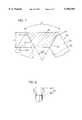
FIG. 8 is a perspective view of a shaped part having a hexagon head like a bolt;
FIG. 9 is a plan view of a die for forming the part of FIG. 8;
FIG. 10 is a side elevation in section taken along the line B--B in FIG. 9 and showing the die;
FIG. 11 is a plan view of a die for forming the flanged nut shown in FIG. 13;
FIG. 12 is a side elevation in section of the die shown in FIG. 11;
FIG. 13 is a perspective view of the flanged nut; and
FIG. 14 is a plan view of a conventional die.
DETAILED DESCRIPTION OF THE PREFERRED EMBODIMENTS First Embodiment
An embodiment of the invention will be described below with reference to the drawings concerned.
FIG. 1 is a plan view showing a forging or cold-pressing tool, more specifically, a die for forming a hexagon nut by forging or cold pressing, and FIG. 4 is a side elevation in section taken along the line A--A in FIG. 1.
As is already known, the die comprises a case 1 formed with a hexagonal nib socket 11 in one end coaxially therewith, and a nib 2 held in the case 1 by a press fit or shrink fit.
The nib 2 comprises six nib pieces 3 made of cemented carbide and having an isosceles trapezoidal cross section. The nib pieces 3 are arranged in an annular form, each with the shorter side thereof positioned inside.
Before the nib pieces 3 are fitted into the case 1, each nib piece 3 has opposite end faces 31, 31 which are slanted as seen in FIG. 2, and the end faces 31, 31 make an angle α which is slightly smaller than 60°. When the nib pieces 3 are arranged annularly with the shorter sides thereof positioned inside and with the opposed inside edges of each pair of adjacent nib pieces 3, 3 in contact with each other, an outwardly enlarging clearance 6 is created between the pair of nib pieces 3, 3 as shown in FIG. 2.
The nib pieces 3 in the state of FIG. 2 are pressed from outside, whereby the butting end faces 31, 31 of each pair of adjacent nib pieces 3, 3 are elastically deformed and pressed into contact with each other over the entire areas thereof. In this state, the case 1 is caused to hold the nib pieces 3 in its nib socket 11. With the nib pieces 3 held in the case 1 as shown in FIG. 1, no clearance occurs between the butting end faces 31, 31 of each pair of adjacent nib pieces 3, 3.
The angle α formed by the end faces 31, 31 of each nib piece 3 is suitable insofar as the entire end faces 31, 31 of each pair of adjacent nib pieces 3, 3 can be pressed into contact with each other by the elastic deformation of the nib pieces 3. The angle can be determined optimally by calculation as by the finite element method, with consideration given, for example, to the interference involved in the insertion of the nib 2 in the cavity 11, the thickness H of the nib piece 3 between its long side and short side and the material of the nib piece 3.
According to the present embodiment, the angle α is 59°50', while this angle can be at least 59°30' to less than 60°.
The case 1 can be caused to hold therein the nib 2 comprising the combination of six nib pieces 3 and as fitted in a sleeve 5 as indicated in a broken line in FIG. 1. In this case, the sleeve 5 has a regular hexagonal nib socket 11 for holding the nib 2 elastically deformed with the butting end faces 31, 31 of each pair of adjacent nib pieces 3, 3 entirely in pressing contact with each other, and is circular in outer periphery. The case 1 is then formed with a circular sleeve socket 12 for inserting therein the sleeve 5 by a press fit or shrink fit.
The pressure acting between the abutting end faces 31, 31 of the adjacent nib pieces 3, 3 according to the embodiment is indicated by arrows of varying lengths in FIG. 3. It is seen that the pressure increases from portion to portion toward the die bore 4. Accordingly, even if the blank is pressed within the die bore 4 in such a direction that the outer periphery thereof is enlarged, the butting end faces of the adjacent nib pieces 3, 3 are prevented from forming therebetween a clearance which would permit the material of the blank to bite in. Consequently, the blank is precluded from biting in between the butting end faces and developing a burr, whereby the tool can be assured of a lengthened life.
At least one of the entire inner surface of the nib socket 11 and the surface of each nib piece 3 may be coated with a modification layer having resistance to seizure, such as a TiC or TiCN layer formed by chemical vapor deposition (CVD) or TiN layer formed by physical vapor deposition (PVD). Since the nib pieces 3 elastically deform when press-fitted into the case 1 as previously stated, an extremely great frictional force acts between the inner surface of the nib socket 11 and the nib pieces 3, as well as between the adjacent nib pieces 3, 3. However, if the seizure-resistant modification layer is formed over the surface of the nib socket 11 and/or the surfaces of the nib pieces 3, an enhanced effect is available to prevent the seizure of the nib pieces 3 to the case 1.
Second Embodiment
FIG. 5 shows another embodiment, i.e., a nib 2a having a circular outer periphery and comprising six nib pieces 3a. The nib 2a is shown before it is held in a case.
Each of the nib pieces 3a resembles an isosceles trapezoid in shape but differs therefrom in that the nib piece 3a has an outer side 34 opposite to a die bore 4 and shaped in a circular-arc form.
Opposite end faces 31a, 31a of the nib piece 3a make an angle α which is not smaller than 59°30' to less than 60° as in the above embodiment.
When the nib 2a is held tightened up in a circular nib socket of the case, the clearance between each pair of adjacent nib pieces 3a, 3a is eliminated by the elastic deformation of the nib pieces 3a. This produces the same effect as previously described.
Third Embodiment
FIG. 6 shows another embodiment, in which four isosceles trapezoidal nib pieces 3b are combined to define a square die bore 4b.
Opposite end faces 31b, 31b of the nib piece 3b make an angle α which is not smaller than 89°30' to less than 90°.
When the four nib pieces 3b are held tightened up in a square nib socket of a case, the clearance between each pair of adjacent nib pieces 3b, 3b is eliminated by the elastic deformation of the nib pieces 3b. This produces the same effect as previously described.
Fourth Embodiment
FIG. 7 shows another embodiment, i.e., a nib 2c which comprises six nib pieces 3c defining a hexagonal die bore 4c.
Before assembly, each of the nib pieces 3c has at each end thereof two faces 32 and 33 toward the short side and toward the long side, respectively. The faces 32, 32 of the nib piece 3c toward the short side thereof form an angle of 60°, while the faces 33, 33 toward the long side form an angle which is different from this angle and is not smaller than 59°30' to less than 60°.
Based on the distance H between the parallel sides of the nib piece 3c, the corresponding distance of the portion having faces 32, 32 making the angle of 60° is preferably 1/4 to 1/6H.
The six nib pieces 3c are arranged in an annular form, with the short sides thereof positioned inside and with the bore-side end faces of each pair of adjacent nib pieces 3c, 3c entirely in contact with each other, and the arrangement of the nib pieces 3c is pressed from outside and thereby elastically deformed to press the whole end faces of the adjacent nib pieces 3c, 3c into contact with each other over the entire areas thereof. A case 1 is caused to hold the nib prices 3c in this state, directly or as fitted in a sleeve.
The bore-side end faces 32, 32 of each nib piece 3c form an angle of 60°, so that when the nib pieces 3c are arranged annularly before being fitted into the case 1, the bore-side faces 32, 32 of the adjacent nib pieces 3c can be brought into face-to-face contact with each other. Consequently, the arrangement of nib pieces 3c can be pressed from outside with the nib pieces 3c prevented from shifting relative to one another without the necessity of using a special jig, and can therefore be fitted into the case 1 easily.
The embodiment of FIG. 7 can of course be applied to the case wherein four nib pieces 3b are assembled into a nib 2b as shown in FIG. 6.
Fifth Embodiment
This embodiment is a forging or cold-pressing tool for producing a shaped part such as a bolt having a hexagon head 81 and a shank 82 extending therefrom as shown in FIG. 8. This embodiment has the same feature as the foregoing embodiments in that butting end faces of each pair of adjacent nib pieces 3, 3 are prevented from forming therebetween a clearance permitting the material of the blank to bite in.
FIG. 9 is a plan view of the tool of this embodiment, and FIG. 10 is a side elevation in section taken along the line B--B in FIG. 9. Coaxially formed in a case 1 are a bore 12 tapered toward a front end thereof and providing an opening at this end, and a straight bore 13 communicating with the tapered bore 12 and providing an opening at a rear end of the case 1.
The case 1 has a sleeve 5 fitting in the tapered bore 12, and a nib support 7 and a pushing-up member 9 which are fitted in the straight bore 13. The nib support 7 is positioned on the upper side of the pushing-up member 9. The sleeve 5 is formed on its axis with a tapered nib socket 11 regular hexagonal and having a nib 2 press-fitted therein. The sleeve 5 is formed at each corner of its nib socket 11 with a round recess 51 for stress relief (see FIG. 9).
The nib 2 comprises six nib pieces 3 of cemented carbide having an isosceles trapezoidal cross section and arranged in an annular form with their short sides positioned inside. The nib 2 centrally has an upper die portion 41 in the form of a hexagonal bore in conformity with the shape of the hexagon head 81 of the shaped part 8.
The longer side, i.e., the shorter side, of the nib piece 3 is in the form of a tapered surface 30 conforming to the tapered nib socket 11 of the sleeve 5. The nib support 7 is centrally formed with a lower die portion 71 in conformity with the shank 82 of the shaped part 8. The nib support 7 has a knockout pin guide bore 72 coaxial therewith and communicating with the lower die portion 71.
The upper die portion 41 of the nib 2 and the lower die portion 71 of the nib support 7 provide a die bore 4 shaped in conformity with the shape of the part 8. When a blank is inserted into the upper die portion 41 and the lower die portion 71 and pressed from therearound, a shaped part 8 is produced.
Before the nib pieces 3 are fitted into the case 1, the slanting end faces 31, 31 of each nib piece 3 make an angle α which is slightly smaller than 60° also in this embodiment as shown in FIG. 2.
The nib pieces 3 in the state of FIG. 2 are pressed from outside to elastically deform each pair of adjacent nib pieces 3, 3 and press the opposed slanting end faces 31, 31 thereof into contact with each other over the entire areas thereof.
In this state, the sleeve 5 is caused to hold the nib pieces 3 in its nib socket 11. With the nib pieces 3 held in the sleeve 5, no clearance occurs between the butting slanting end faces 31, 31 of each pair of adjacent nit pieces 3, 3, whereby the material of the blank can be prevented from biting in between the butting end faces of the nib pieces 3, 3 to preclude formation of a burr.
A seizure-resistant modification layer may be formed by CVD or PVD on the entire surfaces of the nib pieces 3, the surface of the case 1 defining the tapered bore 12 and the surface of the sleeve 5 defining the nib socket 11 as in the embodiment described.
The nib may have a circular outer periphery provided by the nib pieces 2a shown in FIG. 5. Further as shown in FIG. 7, six nib pieces 3c may be used to define a hexagonal die bore 4c, such that based on the distance H between the parallel sides of each nib piece 3c, the corresponding distance of the portion forming an angle of 60° is 1/4 to 1/6H. Further for producing parts having a square head, four isosceles trapezoidal nib pieces 3b may be combined to provide a square upper die portion 4b as shown in FIG. 6. When such nib pieces are in any of these arrangements and held as tightened up in the nib socket 11 of the sleeve 5, the clearance between the adjacent nib pieces is eliminated by the elastic deformation of the nib pieces, whereby the same effect as described above can be obtained.
Sixth Embodiment
FIGS. 11 and 12 are a plan view and a view in vertical section of a die for producing the cold-pressed nut 8a having a flange and shown in FIG. 13. The nut 8a comprises a flange 83 in the form of a disk, and a nut portion 84 provided on the flange 83 and having a smaller diameter than the flange 83.
The die has inside thereof a nib 2 comprising six nib pieces 3 inserted in a sleeve 5 by a press fit. The nib 2 is formed with an upper die portion 41 for forming a hexagonal portion and the flange 83 on a blank, and a nib support 7 is formed with a lower die portion 71 corresponding to the nut portion 84.
The combination of nib pieces 3 is the same as already described with reference to FIGS. 3 and 4, and will therefore not be described again.
The present invention is not limited to the dies of the embodiments but can be embodied generally as forging or cold-pressing tools having split nibs, such as forging or cold-pressing punches and dies for trimming bolt heads to a polygonal form.

Claims (4)

What is claimed is:
1. A forging or cold-pressing tool comprising a plurality of nib pieces arranged in an annular form in combination, each of the nib pieces having an approximately isosceles trapezoidal cross section, slanting faces at respective opposite ends thereof and a shorter side positioned inwardly of the annular arrangement, and a case having the nib pieces held therein to define a regular polygonal die bore by the nib pieces inside thereof and being used to press a blank, the tool being characterized in that the opposite ends of each nib piece before assembly make an angle α smaller than an angle obtained by dividing 360° by the number of nib pieces, an outwardly enlarging clearance being created between the pair of nib pieces which are arranged annularly with the shorter sides thereof positioned inside, the nib pieces being elastically deformed by a tightening force of the case when held in the case, whereby the abutting end faces of each pair of adjacent nib pieces are entirely pressed into contact with each other under a pressure increasing from an outer end portion to a portion toward the die bore, and the abutting end faces of the adjacent nib pieces resisting forming therebetween a clearance which would permit the material of the blank to enter between the adjacent contacting nibs.
2. A forging or cold-pressing tool according to claim 1 wherein the case is provided inside thereof with a nib support for supporting thereon the nib pieces arranged in the annular form, and a nib socket having the nib pieces inserted therein by a press fit, and the die bore for inserting a blank therein comprises an upper die portion formed in the center of the nib pieces fitted in the nib socket, and a lower die portion formed in the nib support.
3. A forging or cold-pressing tool according to claim 2 wherein at least one of the nib socket and each nib piece is formed over a surface thereof with a modification layer having resistance to seizure.
4. A forging or cold-pressing tool according to claim 1 wherein at least one of an inner surface of the case and an outer surface of each nib piece is formed with a modification layer having resistance to seizure.
US08/977,085 1996-11-25 1997-11-24 Forging or cold-pressing tool and method of assembling same Expired - Fee Related US5956993A (en)

Applications Claiming Priority (2)

Application Number Priority Date Filing Date Title
JP8313163A JP2908361B2 (en) 1996-11-25 1996-11-25 Forging and forging tools and methods of making
JP8-313163 1996-11-25

Publications (1)

Publication Number Publication Date
US5956993A true US5956993A (en) 1999-09-28

Family

ID=18037868

Family Applications (1)

Application Number Title Priority Date Filing Date
US08/977,085 Expired - Fee Related US5956993A (en) 1996-11-25 1997-11-24 Forging or cold-pressing tool and method of assembling same

Country Status (2)

Country Link
US (1) US5956993A (en)
JP (1) JP2908361B2 (en)

Cited By (6)

* Cited by examiner, † Cited by third party
Publication number Priority date Publication date Assignee Title
US6370933B1 (en) * 1999-02-26 2002-04-16 General Electric Company Die and method for reducing controlling the formation of flash on parts
RU2493930C1 (en) * 2012-04-10 2013-09-27 Федеральное государственное бюджетное образовательное учреждение высшего профессионального образования "Уфимский государственный авиационный технический университет" Multifaceted part heading female die
RU2496596C1 (en) * 2012-03-30 2013-10-27 Федеральное государственное бюджетное образовательное учреждение высшего профессионального образования "Уфимский государственный авиационный технический университет" Multifaceted part heading female die
US20160045945A1 (en) * 2014-08-18 2016-02-18 Kamax Holding Gmbh & Co. Kg Die module set for pressing tools for producing screws
CN111687370A (en) * 2020-06-22 2020-09-22 浙江明泰控股发展股份有限公司 Forming process and forming device of cap nut
RU2761843C1 (en) * 2021-05-21 2021-12-13 Акционерное Общество «Уфимское агрегатное производственное объединение»(АО "УАПО") Matrix for parts upsetting

Families Citing this family (1)

* Cited by examiner, † Cited by third party
Publication number Priority date Publication date Assignee Title
JP6922773B2 (en) * 2017-03-16 2021-08-18 愛知製鋼株式会社 Forging die

Citations (8)

* Cited by examiner, † Cited by third party
Publication number Priority date Publication date Assignee Title
US567606A (en) * 1896-09-15 mccool
US3823598A (en) * 1968-04-19 1974-07-16 M Freeman Segmental dies
US4095449A (en) * 1975-06-09 1978-06-20 The Valeron Corporation Coated punch
US4222260A (en) * 1978-05-15 1980-09-16 Wsp Industries Corporation Warm forging of connecting rod caps
US4417464A (en) * 1980-03-18 1983-11-29 Mitsutoyo Kiko Co., Ltd. Nib for forming tool for bolt heads or nuts
US4574607A (en) * 1983-02-03 1986-03-11 Kyocera Corporation Can end seaming tool
US4982596A (en) * 1990-01-26 1991-01-08 Buell Industries, Inc. Die for manufacturing a fastener blank
US4984445A (en) * 1989-05-18 1991-01-15 Agency Of Industrial Science And Technology, Ministry Of International Trade And Industry Ceramic isothermal forging die

Patent Citations (8)

* Cited by examiner, † Cited by third party
Publication number Priority date Publication date Assignee Title
US567606A (en) * 1896-09-15 mccool
US3823598A (en) * 1968-04-19 1974-07-16 M Freeman Segmental dies
US4095449A (en) * 1975-06-09 1978-06-20 The Valeron Corporation Coated punch
US4222260A (en) * 1978-05-15 1980-09-16 Wsp Industries Corporation Warm forging of connecting rod caps
US4417464A (en) * 1980-03-18 1983-11-29 Mitsutoyo Kiko Co., Ltd. Nib for forming tool for bolt heads or nuts
US4574607A (en) * 1983-02-03 1986-03-11 Kyocera Corporation Can end seaming tool
US4984445A (en) * 1989-05-18 1991-01-15 Agency Of Industrial Science And Technology, Ministry Of International Trade And Industry Ceramic isothermal forging die
US4982596A (en) * 1990-01-26 1991-01-08 Buell Industries, Inc. Die for manufacturing a fastener blank

Cited By (8)

* Cited by examiner, † Cited by third party
Publication number Priority date Publication date Assignee Title
US6370933B1 (en) * 1999-02-26 2002-04-16 General Electric Company Die and method for reducing controlling the formation of flash on parts
RU2496596C1 (en) * 2012-03-30 2013-10-27 Федеральное государственное бюджетное образовательное учреждение высшего профессионального образования "Уфимский государственный авиационный технический университет" Multifaceted part heading female die
RU2493930C1 (en) * 2012-04-10 2013-09-27 Федеральное государственное бюджетное образовательное учреждение высшего профессионального образования "Уфимский государственный авиационный технический университет" Multifaceted part heading female die
US20160045945A1 (en) * 2014-08-18 2016-02-18 Kamax Holding Gmbh & Co. Kg Die module set for pressing tools for producing screws
CN105363817A (en) * 2014-08-18 2016-03-02 卡迈锡控股两合公司 Die module set for pressing tools for producing screws
CN105363817B (en) * 2014-08-18 2020-02-21 卡迈锡控股两合公司 Female die module group of extrusion die for manufacturing screw
CN111687370A (en) * 2020-06-22 2020-09-22 浙江明泰控股发展股份有限公司 Forming process and forming device of cap nut
RU2761843C1 (en) * 2021-05-21 2021-12-13 Акционерное Общество «Уфимское агрегатное производственное объединение»(АО "УАПО") Matrix for parts upsetting

Also Published As

Publication number Publication date
JPH10156475A (en) 1998-06-16
JP2908361B2 (en) 1999-06-21

Similar Documents

Publication Publication Date Title
JP4801837B2 (en) A spiral drive system for threaded fasteners
US8371660B2 (en) Load transmitting insert for a soft spline body
US4768895A (en) Captive ball and socket joint
US10184508B2 (en) One-piece self-locking nut
US5308285A (en) Method of making a bolt and washer assembly
GB2325035A (en) Interference bolt connection creating plastic deformation within ajoining holes to secure strict axial alignment
US20020197104A1 (en) Polygon connection assembly
US5956993A (en) Forging or cold-pressing tool and method of assembling same
JPS627406B2 (en)
JP2009522527A (en) Precision placement and low pressure repositioning of powder metal components
US10760610B2 (en) Fastener
JP2001527630A (en) New system for holding and tightening screws
US11685027B2 (en) Non-magneiic locking sleeve
US20070212191A1 (en) Two piece weld nut
JP2895029B2 (en) Forging and forging tools
US4233879A (en) Grooved fastener
JP3739602B2 (en) bolt
JP3272265B2 (en) Lock nut
JP4278822B2 (en) Self-forming bolt
JP2895028B2 (en) Forging and forging tools
JP2509446B2 (en) How to fix screws to metal plate
JP2513468Y2 (en) Valve cotter
JPH04129913U (en) Fastening device
JPS6224013A (en) Expanding anchor
JPS5824644Y2 (en) Positioning fastening bolt with fall prevention

Legal Events

Date Code Title Description
AS Assignment

Owner name: AKAMATSU FORSYS CO., LTD., JAPAN

Free format text: ASSIGNMENT OF ASSIGNORS INTEREST;ASSIGNOR:AKAMATSU, KEN-ICHI;REEL/FRAME:008835/0320

Effective date: 19971117

CC Certificate of correction
FEPP Fee payment procedure

Free format text: PAT HOLDER CLAIMS SMALL ENTITY STATUS, ENTITY STATUS SET TO SMALL (ORIGINAL EVENT CODE: LTOS); ENTITY STATUS OF PATENT OWNER: SMALL ENTITY

FPAY Fee payment

Year of fee payment: 4

FPAY Fee payment

Year of fee payment: 8

REMI Maintenance fee reminder mailed
LAPS Lapse for failure to pay maintenance fees
STCH Information on status: patent discontinuation

Free format text: PATENT EXPIRED DUE TO NONPAYMENT OF MAINTENANCE FEES UNDER 37 CFR 1.362

FP Lapsed due to failure to pay maintenance fee

Effective date: 20110928