US5941161A - Piston type compressor - Google Patents
Piston type compressor Download PDFInfo
- Publication number
- US5941161A US5941161A US08/986,263 US98626397A US5941161A US 5941161 A US5941161 A US 5941161A US 98626397 A US98626397 A US 98626397A US 5941161 A US5941161 A US 5941161A
- Authority
- US
- United States
- Prior art keywords
- piston
- compressor
- cavity
- set forth
- bore
- Prior art date
- Legal status (The legal status is an assumption and is not a legal conclusion. Google has not performed a legal analysis and makes no representation as to the accuracy of the status listed.)
- Expired - Fee Related
Links
Images


Classifications
-
- F—MECHANICAL ENGINEERING; LIGHTING; HEATING; WEAPONS; BLASTING
- F04—POSITIVE - DISPLACEMENT MACHINES FOR LIQUIDS; PUMPS FOR LIQUIDS OR ELASTIC FLUIDS
- F04B—POSITIVE-DISPLACEMENT MACHINES FOR LIQUIDS; PUMPS
- F04B27/00—Multi-cylinder pumps specially adapted for elastic fluids and characterised by number or arrangement of cylinders
- F04B27/08—Multi-cylinder pumps specially adapted for elastic fluids and characterised by number or arrangement of cylinders having cylinders coaxial with, or parallel or inclined to, main shaft axis
- F04B27/0873—Component parts, e.g. sealings; Manufacturing or assembly thereof
- F04B27/0878—Pistons
-
- F—MECHANICAL ENGINEERING; LIGHTING; HEATING; WEAPONS; BLASTING
- F05—INDEXING SCHEMES RELATING TO ENGINES OR PUMPS IN VARIOUS SUBCLASSES OF CLASSES F01-F04
- F05C—INDEXING SCHEME RELATING TO MATERIALS, MATERIAL PROPERTIES OR MATERIAL CHARACTERISTICS FOR MACHINES, ENGINES OR PUMPS OTHER THAN NON-POSITIVE-DISPLACEMENT MACHINES OR ENGINES
- F05C2251/00—Material properties
- F05C2251/14—Self lubricating materials; Solid lubricants
-
- F—MECHANICAL ENGINEERING; LIGHTING; HEATING; WEAPONS; BLASTING
- F05—INDEXING SCHEMES RELATING TO ENGINES OR PUMPS IN VARIOUS SUBCLASSES OF CLASSES F01-F04
- F05C—INDEXING SCHEME RELATING TO MATERIALS, MATERIAL PROPERTIES OR MATERIAL CHARACTERISTICS FOR MACHINES, ENGINES OR PUMPS OTHER THAN NON-POSITIVE-DISPLACEMENT MACHINES OR ENGINES
- F05C2253/00—Other material characteristics; Treatment of material
- F05C2253/12—Coating
Definitions
- the present invention relates to compressors that are used in vehicle air conditioners. More particularly, the present invention pertains to sliding structure of pistons in a compressor.
- a typical compressor used in a vehicle has the following construction.
- the compressor includes a housing, and a cylinder block constitutes a part of the housing.
- a crank chamber is defined in the housing.
- a drive shaft is rotatably supported in the crank chamber.
- the cylinder block has cylinder bores formed therein.
- a piston is reciprocally housed in each cylinder bore.
- a cam plate is supported on and rotates integrally with the drive shaft in the crank chamber.
- Each piston is connected to the cam plate by means of shoes. Rotation of the drive shaft is converted into linear reciprocation of the pistons by the cam plate. Refrigerant gas in the cylinder bores is compressed by the reciprocation.
- the inertial force acting on each piston becomes greatest when the piston shifts from the suction stroke to the compression stroke.
- the inertial force of the piston acts on the cam plate.
- the piston receives a reaction force from the cam plate.
- the reaction force includes a lateral component that is directed radially outward from the axis of the cam plate. This component presses a part of each piston head against the inner wall of the associated cylinder bore. This lateral component of the reaction force will be referred to as the lateral force.
- the inertial force of the pistons increases as the weight of the piston is increased. An increased inertial force of the pistons results in a greater lateral force acting on each piston.
- the housing which includes the cylinder block, and the pistons are made of aluminum alloy, which is light, for reducing the weight of the compressor. Therefore, when a piston is reciprocating in the associated cylinder bore, the above described lateral force prevents the piston from smoothly sliding with respect to the cylinder bore.
- an improved compressor includes a bore, a compression chamber defined within the bore and a piston.
- the piston moves within the bore to compress gas in the compression chamber and seals the compression chamber.
- the piston includes a cavity, a peripheral surface and an element for smoothing the movement of the piston.
- the cavity reduces the weight of the piston.
- the peripheral surface has a first surface to form a compression chamber seal and a second surface to a receive a lateral reaction force caused by operation of the compressor.
- the smoothing element is located between the second surface of the piston and the bore.
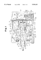
- FIG. 1 is a cross-sectional view illustrating a variable displacement compressor according to a first embodiment of the present invention
- FIG. 2 is a perspective view illustrating a piston of the compressor shown in FIG. 1;
- FIG. 3 is an enlarged partial cross-sectional view illustrating the piston of FIG. 2 taken along line 3--3 of FIG. 1;
- FIG. 4 is a perspective view illustrating a piston of a compressor according to a second embodiment of the present invention.
- FIG. 5 is an enlarged partial cross-sectional view illustrating a variable displacement compressor according to a third embodiment of the present invention.
- FIG. 6 is a perspective view illustrating a piston of the compressor shown in FIG. 5;
- FIG. 7 is a perspective view of the piston of FIG. 6 viewed from a different direction.
- variable displacement compressor of a single-headed piston type according to a first embodiment of the present invention will be described with reference to FIGS. 1 to 3.
- a front housing 11 is coupled to the front end of a cylinder block 12.
- a rear housing 13 is coupled to the rear end of the cylinder block 12.
- the front housing 11, the cylinder block 12, and the rear housing 13 constitute a housing of the compressor.
- the front housing 11, the cylinder block 12 and the rear housing 13 are made of, for example, aluminum alloy.
- a suction chamber 13a and a discharge chamber 13b are defined in the rear housing 13.
- a valve plate 14 having suction flaps 14a and discharge flaps 14b is arranged between the rear housing 13 and the cylinder block 12.
- a crank chamber 15 is defined in the front housing 11 in front of the cylinder block 12.
- a drive shaft 16 extends through the crank chamber 15, the front housing 11 and the cylinder block 12.
- a pair of radial bearings 17 rotatably support the drive shaft 16.
- a lug plate 18 is fixed to the drive shaft 16.
- a swash plate 19, which functions as a cam plate, is fitted to the drive shaft 16 in the crank chamber 15.
- the swash plate 19 is supported so that it is slidable in the axial direction of the drive shaft 16 and inclinable with respect to the drive shaft 16.
- the swash plate 19 is connected to the lug plate 18 by means of a hinge mechanism 20.
- the hinge mechanism 20 guides the movement of the swash plate 19 in the axial direction of the drive shaft 16 and the inclination of the swash plate 19 with respect to the drive shaft 16.
- the hinge mechanism 20 also rotates the swash plate 19 integrally with the drive shaft 16.
- a stopper 19a is provided on the front surface of the swash plate 19.
- the abutment of the stopper 19a against the lug plate 18 determines the maximum inclination position of the swash plate 19.
- a stopper ring 16b is provided on the drive shaft 16. The abutment of the swash plate 19 against the stopper ring 16b restricts further inclination of the swash plate 19 and thus determines the minimum inclination position of the swash plate 19.
- Cylinder bores 12a extend through the cylinder block 12.
- a single-headed piston 21 is housed in each cylinder bore 12a.
- Each piston 21 is integrally molded with aluminum alloy and has a rear portion, or a head 21a, and a front portion, or a skirt 21b.
- the head 21a of each piston 21 is slidably accommodated in the associated cylinder bore 12a.
- the skirt 21b is provided with a slot facing the swash plate 19.
- a concave receiving surface 21c is defined in each of the opposing walls of the slot. Each receiving surface 21c receives the semispherical portion of a shoe 22.
- the periphery of the swash plate 19 is fitted into the slot of each piston skirt 21b and is slidably held between the flat portions of the associated pair of shoes 22.
- a thrust bearing 23 is arranged between the lug plate 18 and the front wall of the front housing 11. The front housing 11 receives the reaction force that acts on each piston 21 during compression of the gas by way of the shoes 22, the swash plate 19, the hinge mechanism 20, the lug plate 18, and the thrust bearing 23.
- a pressurizing passage 24 extends through the cylinder block 12, the valve plate 14, and the rear housing 13 to connect the discharge chamber 13b with the crank chamber 15.
- a displacement control valve 25 is arranged in the rear housing 13 with the pressurizing passage 24 extending therethrough.
- the control valve 25 has a valve hole 27, a valve body 26 faced toward the valve hole 27, and a diaphragm 28 for adjusting the opened area of the valve hole 27.
- a pressure communicating passage 29 is provided to expose one side of the diaphragm 28 to the pressure (suction pressure Ps) of the suction chamber 13a.
- the diaphragm 28 moves the valve body 26 and adjusts the area of the valve hole 27 opened by the valve body 26 in accordance with the communicated suction pressure Ps.
- the control valve 25 alters the amount of refrigerant gas flowing into the crank chamber 15 through the pressurizing passage 24 from the discharge chamber 13b and adjusts the pressure Pc of the crank chamber 15. Changes in the pressure Pc of the crank chamber 15 alter the difference between the pressure Pc of the crank chamber 15 acting on the bottom surface of each piston 21 (the left surface as viewed in FIG. 1) and the pressure of the associated cylinder bore 12a acting on the head surface of the piston 21 (the right surface as viewed in FIG. 1). The inclination of the swash plate 19 is altered in accordance with changes in the pressure difference. This, in turn, alters the stroke of the piston 21 and varies the displacement of the compressor.
- a pressure relieving passage 30 connects the crank chamber 15 to the suction chamber 13a.
- the relieving passage 30 is constituted by an axial passage 16a extending through the center of the drive shaft 16, a retaining bore 12b defined in the center of the cylinder block 12, a pressure releasing groove 12c extending through the rear surface of the cylinder block 12, and a pressure releasing bore 14c extending through the valve plate 14.
- a radial inlet of the axial passage 16a is connected with the crank chamber 15 at the vicinity of the front radial bearing 17. A certain amount of the refrigerant gas in the crank chamber 15 is constantly drawn into the suction chamber 13a through the relieving passage 30.
- a thrust bearing 31 and a coil spring 32 are arranged in the retaining bore 12b between the rear end of the drive shaft 16 and the valve plate 14.
- each piston 21 has a rotation restriction 33 defined at the end of the skirt 21b.
- the restriction 33 includes an arcuate surface that faces the inner wall of the front housing 11. The radius of curvature of the arcuate surface is substantially the same as that of the inner wall of the front housing 11. When the piston 21 moves reciprocally, the arcuate surface of the restriction 33 contacts the inner wall of the front housing 11. This prevents the piston 21 from rotating about its axis.
- a pair of cavities 34 are symmetrically defined in the piston head 21a.
- the cavities 34 are angularly spaced apart by 180 degrees and extend in the longitudinal direction of the head 21a.
- a pair of pressure receiving surfaces 36 are defined on opposite sides of the cavities 34.
- the head 21a also includes a seal 35, which is formed continuously with the receiving surfaces 36, on the rear end of the pistons 21.
- the seal 35 is circularly defined about the head 21a and substantially the whole area of the seal 35 contacts the inner wall of the cylinder bore 12a.
- An annular groove 37 is formed in the periphery of the seal 35.
- a piston ring 38 is fitted in the groove 37.
- the inertial force of the piston 21 acts on the cam plate.
- the piston 21 receives a reaction force from the swash plate 19.
- the reaction force includes a lateral component that is directed radially outward from the axis of the swash plate 19. A reaction to this component, or a lateral force, is received by the pressure receiving surfaces 36 of the piston head 21a.
- the cavities 34 are formed either when molding the piston 21 or by machining the molded piston 21.
- the cavities 34 reduce the weight of the piston 21. Since the piston ring 38 positively seals the space between the piston 21 and the cylinder bore 12a, the width W1 of the seal 35 can be minimized. This further reduces the weight of the piston 21.
- a low friction layer 39 is formed on the pressure receiving surfaces 36. That is, the low friction layer 39 has a low coefficient of friction.
- the layer 39 is constituted by, for example, a coating of fluorocarbon resin having a certain thickness. The layer 39 reduces friction between the cylinder bore 12a and the piston 21.
- the drive shaft 16 is rotated by an external drive means such as an automobile engine.
- the swash plate 19 is integrally rotated with the drive shaft 16 by means of the lug plate 18 and the hinge mechanism 20.
- the rotation of the swash plate 19 is converted to linear reciprocation of each piston 21 in the associated cylinder bore 12a by the shoes 22.
- the reciprocation of the piston 21 draws the refrigerant gas in the suction chamber 13a into the cylinder bore 12a through the associated suction flap 14a.
- the refrigerant gas in the cylinder bore 12a is compressed to a predetermined pressure, the gas is discharged into the discharge chamber 13b through the associated discharge flap 14b.
- the displacement control valve 25 adjusts the opening amount of the pressurizing passage 24 thereby changing the pressure Pc in the crank chamber 15. Changes in the pressure Pc of the crank chamber 15 alter the inclination of the swash plate 19.
- Lateral force refers to a reaction force applied to the piston 21 by the wall of the associated cylinder bore 12a when the peripheral surface of the piston 21 presses against the wall of the cylinder bore 12a.
- the inertial force acting on the piston 21 becomes maximum.
- the inertial force acting on the piston 21 is denoted by F0.
- the inertial force F0 of the piston 21 is applied to the swash plate 19. Accordingly, the piston 21 receives reaction force Fs, which is associated with the inertial force F0, from the inclined swash plate 19.
- the reaction force Fs is divided into component force f1, which acts in the axial direction of the piston 21, and component force f2, which acts in the radial direction of the piston 21.
- component force f2 inclines the skirt 21b of the piston 21 in the direction of the component force f2.
- the pressure receiving surface 36 is pressed by the wall of the cylinder bore 12a by a force corresponding to the component force f2.
- the surface 36 receives reaction force (lateral force) Fa associated with the component force f2, from the wall of the cylinder bore 12a.
- the peripheral surface at the rear end of the piston head 21a receives a reaction force (lateral force) Fb, which is associated with the component force f2, from the wall of the cylinder bore 12a.
- the cavities 34 are formed in the piston 21 apart from the area corresponding to the seal 35 and the pressure receiving surfaces 36. Further, the low friction layer 39 is formed on the seal 35 and the receiving surfaces 36. Thus, the weight of each piston 21 is reduced and frictional resistance between the piston 21 and the cylinder bore 12a is lowered. This allows the piston 21 to smoothly reciprocate in the cylinder bore 12a.
- the lateral force Fa acts on a part of the head 21a that contacts the front end of the cylinder bore 12a.
- the part of the head 21a on which the force Fa acts is spaced as far as possible from the rear end of the piston 21 (the right end in FIG. 1). Therefore, the distance between the point on which the force Fa acts and the point on which the force Fb acts is maximized. In other words, distance between fulcrums on the piston 21 is maximized. As a result, the pressing forces resulting from the component f2 is minimized.
- the cavities 34 reduces the weight of the piston 21. This reduces the inertial force of the piston 21 generated when the piston 21 shifts from the suction stroke to the compression stroke. Accordingly, the lateral forces Fa and Fb, which act on the head 21a of the piston 21 are reduced.
- the low friction layer 39 which is formed on the pressure receiving surfaces 36, reduces frictional resistance between the cylinder bore 12a and the piston 21. As a result, the pistons 21 are smoothly reciprocated in the cylinder bores 12a.
- the piston ring 38 is attached to each piston 21 at the seal 35. Therefore, the width W1 of the seal 35 may be shortened while improving the sealing effectiveness between the seal 35 and the cylinder bore 12a.
- the shortened width W1 reduces the weight of each piston 21.
- the inertial force of the piston 21 is decreased, accordingly.
- the decreased inertial force results in decreased lateral forces Fa, Fb acting on the pistons 21.
- a pair of symmetrical cavities 34 are formed on the head 21a of the piston 21 and are located opposite to each other.
- the cavities 34 are also located on opposite sides of a plane that includes the piston axis C1 and the shaft axis Co.
- the cavities 34 define a narrow pressure receiving surface 36 at a part corresponding to the outer side of the piston 21.
- the low friction layer 39 is formed on the pressure receiving surface 36.
- the weight of the piston 21 is reduced and the lateral force Fa and Fb acting on the head 21a is decreased. Also, the low friction layer 39 smoothes the reciprocation of the pistons 21 in the cylinder bores 12a.
- a pair of cavities 34 are formed in the piston head 21a.
- the cavities 34 are angularly spaced apart by 180 degrees about the axis of the piston 21 and are arranged at different axial positions.
- the low frictional layer 39 is not formed on the pressure receiving surface 36 of the piston head 21a of FIG. 6.
- a cylinder 41 is press fitted in each cylinder bore 12a.
- the cylinder 41 is made of relatively hard metal such as iron.
- the seal 35 and the pressure receiving surface 36 of piston head 21a contact the cylinder 41.
- the wall of the cylinder bores 12a are covered by the cylinder 41. This prevents the pistons 21 from contacting the wall of the cylinder bore 12a, which is made of the same material (aluminum alloy) as the pistons 21.
- the third embodiment has the same advantages as the first and second embodiments.
- the pistons 21 are smoothly reciprocated even if the temperature of the piston 21 and the cylinder 41 is increased by friction.
- the cylinder 41 is simply press fitted in each cylinder bore 12a. This facilitates reduction of frictional resistance between the pressure receiving surface 36 and the cylinder bore 12a.
- the present invention may be embodied in the following forms.
- the following embodiments have substantially the same advantages as the first to third embodiments.
- Alloy plating may be formed on the pressure receiving surface 36 and on the wall of the cylinder bores 12a or on the inner wall of the cylinders 41 for reducing frictional resistance of the piston 21.
- the plating may be formed with an alloy such as nickel and phosphorus, nickel and boron or cobalt, phosphorus and tungsten.
- the pressure receiving surface 36, the wall of the cylinder bore 12a or of the cylinder 41 may be covered with dispersion coating.
- the metal matrix of the dispersion coating may be selected from metals such as nickel, cobalt, iron, silver, spelter, nickel phosphorus alloy, nickel boron ally and cobalt boron alloy.
- the material for dispersed particles may be selected from molybdenum disulfide, tungsten disulfide, graphite, graphite fluoride, polytetrafluoroethylene, fluorocarbon resin, calcium fluoride, boron nitride, silicon carbide, polyvinyl chloride and barium sulfate.
- the pressure receiving surface 36 or the wall of the cylinder bore 12a may be subjected to anodizing for reducing frictional resistance.
- the pressure receiving surface 36, the wall of the cylinder bore 12a or of the cylinder 41 may be coated, for example, with molybdenum disulfide or tungsten disulfide for reducing frictional resistance.
- the inner wall of the cylinder 41 may be coated, for example, with fluorocarbon resin for reducing frictional resistance.
- the present invention may be embodied in double-headed piston type compressors.
- the present invention may be embodied in a compressor having fixed displacement.
Applications Claiming Priority (2)
| Application Number | Priority Date | Filing Date | Title |
|---|---|---|---|
| JP8326840A JPH10169557A (ja) | 1996-12-06 | 1996-12-06 | 圧縮機 |
| JP8-326840 | 1996-12-06 |
Publications (1)
| Publication Number | Publication Date |
|---|---|
| US5941161A true US5941161A (en) | 1999-08-24 |
Family
ID=18192305
Family Applications (1)
| Application Number | Title | Priority Date | Filing Date |
|---|---|---|---|
| US08/986,263 Expired - Fee Related US5941161A (en) | 1996-12-06 | 1997-12-05 | Piston type compressor |
Country Status (4)
| Country | Link |
|---|---|
| US (1) | US5941161A (de) |
| JP (1) | JPH10169557A (de) |
| KR (1) | KR100274497B1 (de) |
| DE (1) | DE19754028A1 (de) |
Cited By (23)
| Publication number | Priority date | Publication date | Assignee | Title |
|---|---|---|---|---|
| US6247391B1 (en) * | 1998-09-10 | 2001-06-19 | Kabushiki Kaisha Toyoda Jidoshokki Seisakusho | Compressor and spring positioning structure |
| US6283012B1 (en) | 1998-12-09 | 2001-09-04 | Kabushiki Kaisha Toyoda Jidoshokki Seisakusho | Compressor piston and method for coating piston |
| US6318502B1 (en) * | 1998-10-13 | 2001-11-20 | Hans Unger | Compressor for producing oil-free compressed air |
| US6324960B1 (en) | 1999-06-15 | 2001-12-04 | Kabushiki Kaisha Toyoda Jidoshokki Seisakusho | Piston for swash plate type compressor, including head portion having lubricant reservoir recess, and method of forming the recess |
| FR2811733A1 (fr) * | 2000-07-12 | 2002-01-18 | Sanden Corp | Piston de compresseur |
| US6357340B1 (en) * | 1999-02-26 | 2002-03-19 | Kabushiki Kaisha Toyoda Jidoshokki Seisakusho | Piston compressor piston |
| WO2002064978A1 (de) * | 2001-02-14 | 2002-08-22 | Daimlerchrysler Ag | Kolben für einen kompressor |
| US20020121189A1 (en) * | 2001-03-02 | 2002-09-05 | Masakazu Murase | Piston type compressor |
| US6474955B1 (en) * | 1999-05-13 | 2002-11-05 | Kabushiki Kaisha Toyoda Jidoshokki Seisakusho | Hinge mechanism for variable displacement compressors |
| US6484621B1 (en) * | 1999-05-28 | 2002-11-26 | Kabushiki Kaisha Toyoda Jidoshokki Seisakusho | Swash plate type compressor wherein piston head has inner sliding portion for reducing local wear |
| US6513417B1 (en) * | 1999-11-08 | 2003-02-04 | Kabushiki Kaisha Toyoda Jidoshokki Seisakusho | Single-headed swash-plate-type compressor with hollowed and ribbed piston |
| US20030075041A1 (en) * | 2001-10-19 | 2003-04-24 | Fuminobu Enokijima | Piston for fluid machine and the fluid machine having the same |
| US6581507B2 (en) * | 2000-07-14 | 2003-06-24 | Kabushiki Kaisha Toyoda Jidoshokki Seisakusho | Single-headed piston type swash plate compressor |
| US20030121413A1 (en) * | 2001-12-28 | 2003-07-03 | Pitla Srinivas S. | Piston anti-rotation mechanism for a swash plate compressor |
| US6663355B2 (en) * | 2000-06-28 | 2003-12-16 | Kabushiki Kaisha Toyoda Jidoshokki Seisakusho | Variable displacement compressor |
| US6694863B1 (en) * | 1999-09-09 | 2004-02-24 | Zexel Valeo Climate Control Corporation | Swash plate compressor |
| US20050098031A1 (en) * | 2001-11-08 | 2005-05-12 | Hyung-Pyo Yoon | Abrasion preventive structure of reciprocating compressor |
| EP1568884A2 (de) * | 2004-02-26 | 2005-08-31 | Delphi Technologies, Inc. | Kolben für einen Taumelscheibenkompressor mit hohlem Kolbenkopf |
| US20050188839A1 (en) * | 2004-03-01 | 2005-09-01 | Anest Iwata Corporation | Oilless reciprocating air compressor |
| WO2007027021A1 (en) * | 2005-09-02 | 2007-03-08 | Halla Climate Control Corporation | Variable capacity swash plate type compressor |
| WO2007046580A1 (en) * | 2005-10-20 | 2007-04-26 | Halla Climate Control Corporation | Variable capacity swash plate type compressor |
| US20090199809A1 (en) * | 2006-06-07 | 2009-08-13 | Iwao Uchikado | Fluid Machine |
| US20150300333A1 (en) * | 2012-10-15 | 2015-10-22 | Hitachi Construction Machinery Co., Ltd. | Hydraulic Rotary Machine |
Families Citing this family (6)
| Publication number | Priority date | Publication date | Assignee | Title |
|---|---|---|---|---|
| KR100558703B1 (ko) * | 1999-03-20 | 2006-03-10 | 한라공조주식회사 | 응력을 최소화하기 위한 피스톤 |
| DE10107424A1 (de) * | 2001-02-14 | 2002-09-26 | Daimler Chrysler Ag | Kolben für einen Kompressor |
| DE10360352B4 (de) * | 2003-12-22 | 2016-03-24 | Volkswagen Ag | Taumelscheibenkompressor für eine CO2 - Klimaanlage mit einer Spaltdicke von 5 bis 20 µm zwischen Hubkolben und Kompressionszylinder |
| DE102004012865A1 (de) * | 2004-03-16 | 2005-10-06 | Volkswagen Ag | Taumelscheibenkompressor für eine Fahrzeugklimaanlage |
| JP4704276B2 (ja) * | 2006-05-23 | 2011-06-15 | サンデン株式会社 | 往復動圧縮機用ピストン |
| JP2016070168A (ja) * | 2014-09-30 | 2016-05-09 | 株式会社ヴァレオジャパン | 斜板式圧縮機用ピストン |
Citations (5)
| Publication number | Priority date | Publication date | Assignee | Title |
|---|---|---|---|---|
| US4519119A (en) * | 1980-11-19 | 1985-05-28 | Kabushiki Kaisha Toyoda Jidoshokki Seisakusho | Method of manufacturing a piston for a swash plate type compressor |
| US4701110A (en) * | 1985-05-20 | 1987-10-20 | Diesel Kiki Co., Ltd. | Swash-plate type rotary compressor with drive shaft, lubrication |
| US5630353A (en) * | 1996-06-17 | 1997-05-20 | General Motors Corporation | Compressor piston with a basic hollow design |
| US5630355A (en) * | 1993-06-21 | 1997-05-20 | Kabushiki Kaisha Toyoda Jidoshokki Seisakusho | Reciprocating type compressor with improved cylinder block |
| US5813315A (en) * | 1994-07-13 | 1998-09-29 | Danfoss A/S | Hydraulic piston machine having sheathing plastic material for reducing friction |
-
1996
- 1996-12-06 JP JP8326840A patent/JPH10169557A/ja active Pending
-
1997
- 1997-12-05 DE DE19754028A patent/DE19754028A1/de not_active Ceased
- 1997-12-05 US US08/986,263 patent/US5941161A/en not_active Expired - Fee Related
- 1997-12-06 KR KR1019970066464A patent/KR100274497B1/ko not_active IP Right Cessation
Patent Citations (5)
| Publication number | Priority date | Publication date | Assignee | Title |
|---|---|---|---|---|
| US4519119A (en) * | 1980-11-19 | 1985-05-28 | Kabushiki Kaisha Toyoda Jidoshokki Seisakusho | Method of manufacturing a piston for a swash plate type compressor |
| US4701110A (en) * | 1985-05-20 | 1987-10-20 | Diesel Kiki Co., Ltd. | Swash-plate type rotary compressor with drive shaft, lubrication |
| US5630355A (en) * | 1993-06-21 | 1997-05-20 | Kabushiki Kaisha Toyoda Jidoshokki Seisakusho | Reciprocating type compressor with improved cylinder block |
| US5813315A (en) * | 1994-07-13 | 1998-09-29 | Danfoss A/S | Hydraulic piston machine having sheathing plastic material for reducing friction |
| US5630353A (en) * | 1996-06-17 | 1997-05-20 | General Motors Corporation | Compressor piston with a basic hollow design |
Cited By (34)
| Publication number | Priority date | Publication date | Assignee | Title |
|---|---|---|---|---|
| US6247391B1 (en) * | 1998-09-10 | 2001-06-19 | Kabushiki Kaisha Toyoda Jidoshokki Seisakusho | Compressor and spring positioning structure |
| US6318502B1 (en) * | 1998-10-13 | 2001-11-20 | Hans Unger | Compressor for producing oil-free compressed air |
| US6283012B1 (en) | 1998-12-09 | 2001-09-04 | Kabushiki Kaisha Toyoda Jidoshokki Seisakusho | Compressor piston and method for coating piston |
| US6357340B1 (en) * | 1999-02-26 | 2002-03-19 | Kabushiki Kaisha Toyoda Jidoshokki Seisakusho | Piston compressor piston |
| US6474955B1 (en) * | 1999-05-13 | 2002-11-05 | Kabushiki Kaisha Toyoda Jidoshokki Seisakusho | Hinge mechanism for variable displacement compressors |
| US6484621B1 (en) * | 1999-05-28 | 2002-11-26 | Kabushiki Kaisha Toyoda Jidoshokki Seisakusho | Swash plate type compressor wherein piston head has inner sliding portion for reducing local wear |
| US6324960B1 (en) | 1999-06-15 | 2001-12-04 | Kabushiki Kaisha Toyoda Jidoshokki Seisakusho | Piston for swash plate type compressor, including head portion having lubricant reservoir recess, and method of forming the recess |
| US6694863B1 (en) * | 1999-09-09 | 2004-02-24 | Zexel Valeo Climate Control Corporation | Swash plate compressor |
| US6513417B1 (en) * | 1999-11-08 | 2003-02-04 | Kabushiki Kaisha Toyoda Jidoshokki Seisakusho | Single-headed swash-plate-type compressor with hollowed and ribbed piston |
| US6663355B2 (en) * | 2000-06-28 | 2003-12-16 | Kabushiki Kaisha Toyoda Jidoshokki Seisakusho | Variable displacement compressor |
| FR2811733A1 (fr) * | 2000-07-12 | 2002-01-18 | Sanden Corp | Piston de compresseur |
| US6581507B2 (en) * | 2000-07-14 | 2003-06-24 | Kabushiki Kaisha Toyoda Jidoshokki Seisakusho | Single-headed piston type swash plate compressor |
| US6925925B2 (en) | 2001-02-14 | 2005-08-09 | Daimlerchrysler Ag | Piston for a compressor |
| WO2002064978A1 (de) * | 2001-02-14 | 2002-08-22 | Daimlerchrysler Ag | Kolben für einen kompressor |
| US20040244579A1 (en) * | 2001-02-14 | 2004-12-09 | Roland Casar | Piston for a compressor |
| US6705207B2 (en) * | 2001-03-02 | 2004-03-16 | Kabushiki Kaisha Toyota Jidoshokki | Piston type compressor |
| US20020121189A1 (en) * | 2001-03-02 | 2002-09-05 | Masakazu Murase | Piston type compressor |
| US20030075041A1 (en) * | 2001-10-19 | 2003-04-24 | Fuminobu Enokijima | Piston for fluid machine and the fluid machine having the same |
| US7028601B2 (en) * | 2001-11-08 | 2006-04-18 | Lg Electronics Inc. | Abrasion preventive structure of reciprocating compressor |
| US20050098031A1 (en) * | 2001-11-08 | 2005-05-12 | Hyung-Pyo Yoon | Abrasion preventive structure of reciprocating compressor |
| US20030121413A1 (en) * | 2001-12-28 | 2003-07-03 | Pitla Srinivas S. | Piston anti-rotation mechanism for a swash plate compressor |
| EP1568884A2 (de) * | 2004-02-26 | 2005-08-31 | Delphi Technologies, Inc. | Kolben für einen Taumelscheibenkompressor mit hohlem Kolbenkopf |
| US20050188835A1 (en) * | 2004-02-26 | 2005-09-01 | Anh Le | Unitary hollowed piston with improved structural strength |
| US6941852B1 (en) * | 2004-02-26 | 2005-09-13 | Delphi Technologies, Inc. | Unitary hollowed piston with improved structural strength |
| EP1568884A3 (de) * | 2004-02-26 | 2009-03-04 | Delphi Technologies, Inc. | Kolben für einen Taumelscheibenkompressor mit hohlem Kolbenkopf |
| US20050188839A1 (en) * | 2004-03-01 | 2005-09-01 | Anest Iwata Corporation | Oilless reciprocating air compressor |
| WO2007027021A1 (en) * | 2005-09-02 | 2007-03-08 | Halla Climate Control Corporation | Variable capacity swash plate type compressor |
| KR101139347B1 (ko) | 2005-09-02 | 2012-04-30 | 한라공조주식회사 | 가변용량형 사판식 압축기 |
| WO2007046580A1 (en) * | 2005-10-20 | 2007-04-26 | Halla Climate Control Corporation | Variable capacity swash plate type compressor |
| US20090148312A1 (en) * | 2005-10-20 | 2009-06-11 | Hewnam Ahn | Variable Capacity Swash Plate Type Compressor |
| KR101104282B1 (ko) * | 2005-10-20 | 2012-01-11 | 한라공조주식회사 | 가변용량형 사판식 압축기 |
| US20090199809A1 (en) * | 2006-06-07 | 2009-08-13 | Iwao Uchikado | Fluid Machine |
| US8210092B2 (en) * | 2006-06-07 | 2012-07-03 | Sanden Corporation | Fluid machine |
| US20150300333A1 (en) * | 2012-10-15 | 2015-10-22 | Hitachi Construction Machinery Co., Ltd. | Hydraulic Rotary Machine |
Also Published As
| Publication number | Publication date |
|---|---|
| KR19980063867A (ko) | 1998-10-07 |
| KR100274497B1 (ko) | 2000-12-15 |
| JPH10169557A (ja) | 1998-06-23 |
| DE19754028A1 (de) | 1998-06-10 |
Similar Documents
| Publication | Publication Date | Title |
|---|---|---|
| US5941161A (en) | Piston type compressor | |
| US5765464A (en) | Reciprocating pistons of piston-type compressor | |
| US6752065B2 (en) | Sliding member and sliding device | |
| US5974946A (en) | Swash plate type compressor using swash plate made of highly wear-resistant material | |
| US5953980A (en) | Piston type compressors | |
| US6010313A (en) | Single-headed piston type compressor | |
| US6116145A (en) | Variable displacement compressor | |
| US6666128B2 (en) | Swash plate in swash plate type compressor | |
| JP2001099056A (ja) | 斜板式圧縮機用ピストン | |
| EP0844389B1 (de) | Schrägscheibenverdichter | |
| US20030066419A1 (en) | Piston for fluid machine and method of manufacturing the same | |
| US20020046647A1 (en) | Compressors | |
| EP1236896B1 (de) | Verdichterkolben | |
| EP1092872A2 (de) | Kolben für Taumelscheibenverdichter | |
| JP3985507B2 (ja) | 斜板型圧縮機 | |
| US5771775A (en) | Device for guiding a piston | |
| JP3878256B2 (ja) | 片斜板式圧縮機 | |
| JP3640088B2 (ja) | 斜板式圧縮機 | |
| EP1158163A2 (de) | Kolben für einen Taumelscheibenverdichter | |
| US20010042438A1 (en) | Piston for swash plate type compressor | |
| EP1188923B1 (de) | Beschichtung einer Schrägscheibe eines Kompressors | |
| JP4314405B2 (ja) | 可変容量型斜板式圧縮機 | |
| EP2042731A2 (de) | Taumelscheibenverdichter | |
| US6386090B2 (en) | Piston type compressor | |
| EP1092873A2 (de) | Zylinderbohrung eines Taumelscheibenkompressors mit Nuten |
Legal Events
| Date | Code | Title | Description |
|---|---|---|---|
| AS | Assignment |
Owner name: KABUSHIKI KAISHA TOYODA JIDOSHOKKI SEISAKUSHO, JAP Free format text: ASSIGNMENT OF ASSIGNORS INTEREST;ASSIGNORS:KIMURA, KAZUYA;OTA, MASAKI;KAYUKAWA, HIROAKI;REEL/FRAME:008899/0610 Effective date: 19971202 |
|
| FEPP | Fee payment procedure |
Free format text: PAYOR NUMBER ASSIGNED (ORIGINAL EVENT CODE: ASPN); ENTITY STATUS OF PATENT OWNER: LARGE ENTITY |
|
| FPAY | Fee payment |
Year of fee payment: 4 |
|
| REMI | Maintenance fee reminder mailed | ||
| LAPS | Lapse for failure to pay maintenance fees | ||
| LAPS | Lapse for failure to pay maintenance fees |
Free format text: PATENT EXPIRED FOR FAILURE TO PAY MAINTENANCE FEES (ORIGINAL EVENT CODE: EXP.); ENTITY STATUS OF PATENT OWNER: LARGE ENTITY |
|
| STCH | Information on status: patent discontinuation |
Free format text: PATENT EXPIRED DUE TO NONPAYMENT OF MAINTENANCE FEES UNDER 37 CFR 1.362 |
|
| FP | Lapsed due to failure to pay maintenance fee |
Effective date: 20070824 |