US5921490A - Bait casting reel with parallel connected clutch operating levers - Google Patents
Bait casting reel with parallel connected clutch operating levers Download PDFInfo
- Publication number
- US5921490A US5921490A US08/976,828 US97682897A US5921490A US 5921490 A US5921490 A US 5921490A US 97682897 A US97682897 A US 97682897A US 5921490 A US5921490 A US 5921490A
- Authority
- US
- United States
- Prior art keywords
- clutch
- spool
- pair
- double
- operating levers
- Prior art date
- Legal status (The legal status is an assumption and is not a legal conclusion. Google has not performed a legal analysis and makes no representation as to the accuracy of the status listed.)
- Expired - Lifetime
Links
- 238000005266 casting Methods 0.000 title 1
- 230000007246 mechanism Effects 0.000 claims abstract description 76
- 210000003813 thumb Anatomy 0.000 claims abstract description 29
- 230000005540 biological transmission Effects 0.000 claims abstract description 8
- 230000033001 locomotion Effects 0.000 claims description 6
- 230000035939 shock Effects 0.000 claims description 2
- 238000010276 construction Methods 0.000 description 4
- 238000004804 winding Methods 0.000 description 3
- 210000003811 finger Anatomy 0.000 description 2
- 230000004048 modification Effects 0.000 description 2
- 238000012986 modification Methods 0.000 description 2
Images


Classifications
-
- A—HUMAN NECESSITIES
- A01—AGRICULTURE; FORESTRY; ANIMAL HUSBANDRY; HUNTING; TRAPPING; FISHING
- A01K—ANIMAL HUSBANDRY; AVICULTURE; APICULTURE; PISCICULTURE; FISHING; REARING OR BREEDING ANIMALS, NOT OTHERWISE PROVIDED FOR; NEW BREEDS OF ANIMALS
- A01K89/00—Reels
- A01K89/015—Reels with a rotary drum, i.e. with a rotating spool
- A01K89/0183—Drive mechanism details
- A01K89/0186—Drive mechanism details with disengageable positive drive components, e.g. a clutch
- A01K89/01901—Reengageable responsive to drive rotation
-
- A—HUMAN NECESSITIES
- A01—AGRICULTURE; FORESTRY; ANIMAL HUSBANDRY; HUNTING; TRAPPING; FISHING
- A01K—ANIMAL HUSBANDRY; AVICULTURE; APICULTURE; PISCICULTURE; FISHING; REARING OR BREEDING ANIMALS, NOT OTHERWISE PROVIDED FOR; NEW BREEDS OF ANIMALS
- A01K89/00—Reels
- A01K89/015—Reels with a rotary drum, i.e. with a rotating spool
- A01K89/0183—Drive mechanism details
- A01K89/0186—Drive mechanism details with disengageable positive drive components, e.g. a clutch
- A01K89/0188—Axially engaged
- A01K89/0189—Coaxial of spool
-
- A—HUMAN NECESSITIES
- A01—AGRICULTURE; FORESTRY; ANIMAL HUSBANDRY; HUNTING; TRAPPING; FISHING
- A01K—ANIMAL HUSBANDRY; AVICULTURE; APICULTURE; PISCICULTURE; FISHING; REARING OR BREEDING ANIMALS, NOT OTHERWISE PROVIDED FOR; NEW BREEDS OF ANIMALS
- A01K89/00—Reels
- A01K89/015—Reels with a rotary drum, i.e. with a rotating spool
- A01K89/0183—Drive mechanism details
- A01K89/01912—Drive mechanism details with level winding
Definitions
- the present invention relates to a double-bearing reel, and specifically concerns a double-bearing reel which has a clutch mechanism in the rotation transmitting mechanism installed between the handle and spool.
- Double-bearing reels used for fishing generally are designed as follows: a spool is supported between a pair of side plates forming the reel body, so that the spool is free to rotate, and this spool is caused to rotate by means of a handle which is installed on one side of the reel body. Furthermore, a rotation transmitting mechanism which includes a clutch mechanism (hereafter referred to simply as a "clutch”) is installed between the handle and spool, so that the rotation of the handle can be transmitted to the spool, or the transmission can be interrupted.
- a rotation transmitting mechanism which includes a clutch mechanism (hereafter referred to simply as a "clutch”) is installed between the handle and spool, so that the rotation of the handle can be transmitted to the spool, or the transmission can be interrupted.
- the present applicant has already proposed a device in which a separate clutch operating lever is installed above the spool in addition to a thumb rest used as a clutch operating lever as described above.
- This separate clutch operating lever is constructed as follows: a lever which is installed on one side plate above the spool, and a bridge which extends from the lever to the other side plate, are formed as an integral unit.
- the bridge is formed so that it covers the top of the spool, the following problem arises: in cases where the fishing line becomes tangled as a result of backlash, etc., the bridge becomes an obstacle so that handling of the tangled fishing line is difficult.
- One object of the present invention is to facilitate handling of the fishing line in cases where the line becomes tangled around the spool in a reel in which respective levers for clutch operation are installed behind the spool and adjacent to both side plates of the reel main body.
- Another object of the present invention is to prevent damage to the clutch operating levers and the members constituting the clutch operating mechanism, and to allow safer handling.
- an improved double-bearing reel is equipped with a reel main body which has a pair of side plates that are installed so that the side plates face each other across a prescribed gap, a spool, having an axis of rotation, which is installed between the pair of side plates so that the spool is free to rotate, a handle which is supported on the reel main body so that the handle is free to rotate, and which is used to rotate the spool, a rotation transmitting mechanism which transmits the rotational force from the handle to the spool, a clutch mechanism which is used for the transmission and interruption of rotational force between the handle and spool, a pair of clutch operating levers which are respectively installed adjacent to the pair of side plates, and which are used to operate the clutch mechanism, a connecting member which is installed below the axis of rotation of the spool, and which connects the pair of clutch operating levers, and a thumb rest which is installed to the rear of the spool between the pair of side plates, and
- the clutch mechanism is switched off by means of the clutch operating levers when the fishing line is to be paid out. As a result, the spool is not rotated by the rotation of the handle. After a prescribed length of fishing line has been paid out, the clutch operating levers are operated so that the clutch mechanism is switched on. In this state, the rotational force of the handle is transmitted to the spool by the rotation transmitting mechanism. Accordingly, the fishing line can be wound around the spool by operating the handle.
- clutch operating levers are installed on both of a pair of side plates.
- the clutch thus can be smoothly operated by thumbing with either the left hand or the right hand.
- the left and right levers are connected by a connecting member which is installed below the spool.
- the left and right levers can be connected without installing a member that creates an obstacle above the spool.
- handling of the fishing line in cases where the line has become wrapped around the spool is facilitated.
- the inventive double-bearing reel is further equipped with a linking mechanism that links the clutch operating levers with the thumb rest. Operation of the clutch thus is further facilitated.
- the connecting member is installed between the spool and the thumb rest. Accordingly, there is no need for any extra space, and the size of the reel can therefore be reduced. Furthermore, the connecting member is protected by the thumb rest. Moreover, if, the system is designed (in combination with the double-bearing reel of the foregoing preferred embodiment) so that the direction of operation of the connecting member when the clutch operating levers are operated and the direction of linked movement of the thumb rest are the same direction, then the connecting member is always positioned to the inside of the thumb rest, so that the connecting member is not exposed.
- the inventive double-bearing reel is further equipped with a shock-absorbing mechanism, preferably installed between the operating levers and the clutch mechanism.
- a shock-absorbing mechanism preferably installed between the operating levers and the clutch mechanism.
- the foregoing clutch mechanism includes a clutch cam, and a pivoting member to which one of the clutch operating levers is affixed.
- the foregoing shock-absorbing mechanism includes an engaging projection which is formed either on the pivoting member or the clutch cam, an engaging recess which is formed in the other of the two parts mentioned above, and which engages with the engaging projection so that relative movement is possible only through a prescribed range, and an urging member which urges the clutch operating levers in a prescribed direction.
- the structure is simple.
- a double-bearing reel comprising a reel main body which includes comprising a pair of opposed side plates; a spool having an upper portion, the spool being installed between the pair of side plates; a handle; a rotation transmitting mechanism which transmits rotational force from the handle to the spool; a clutch mechanism for transmission and interruption of rotational force between the handle and the spool; a pair of clutch operating levers which are respectively installed adjacent to the pair of side plates and which are used to operate the clutch mechanism; a connecting member which connects the pair of clutch operating levers without obstructing access to the upper portion of the spool; and a thumb rest which is installed between the pair of side plates and which is used to operate the clutch mechanism.
- a double-bearing reel which includes: a reel main body comprising a pair of opposed side plates; a spool having an upper portion and a spool shaft, the spool being installed between the pair of side plates; a handle; a rotation transmitting mechanism which transmits rotational force from the handle to the spool; a clutch mechanism for transmission and interruption of rotational force between the handle and the spool, the clutch mechanism including a clutch yoke installed around the spool shaft, a clutch cam which is pivotable about the spool shaft and which includes a disk on which are formed cam surfaces that contact the clutch yoke, a lever attachment element extending upward from the disk, and a back surface, and a clutch plate which includes an engaging element which engages with the back surface of the clutch cam and a second lever attachment element; a plate; a pair of opposed clutch operating levers which are respectively installed adjacent to the pair of side plates and which are used to operate the clutch mechanism, wherein one
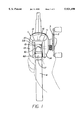
- FIG. 1 is a plan view of a double-bearing reel constructed according to one embodiment of the present invention.
- FIG. 2 is a sectional side view of the double-bearing reel.
- FIG. 3 is a sectional plan view of the double-bearing reel.
- FIG. 4 is a side view of the double-bearing reel with the covers removed.
- FIG. 5 is a magnified partial view of FIG. 1.
- FIG. 6 is an illustration of another embodiment of the present invention (corresponding to FIG. 4).
- the double-bearing reel shown in FIGS. 1 and 2 is equipped with a reel main body 1, a handle 2 (used to rotate the spool) which is installed on one side of the reel main body 1, and a brake knob 3 (used for brake adjustment) which is installed on the reel main body side of the handle 2.
- the reel main body 1 is fastened to a fishing rod 4 via a reel attachment member.
- the reel main body 1 has a frame 12 which has a pair of side plates 10, 11 that are installed on either side of a defined gap, and a first cover 13 and second cover 14 which are respectively mounted on both sides of the frame 12.
- a spool 15 having an upper portion 15a is installed between the pair of side plates 10, 11 so that the spool 15 is free to rotate.
- a level winding mechanism 16 which is used to wind the fishing line uniformly on the spool 15 is installed in front of the spool 15, and a thumb rest 17 is installed to the rear of the spool 15. Furthermore, an opening is formed in the reel main body 1 above the spool 15, so that thumbing can be performed by inserting the thumb into the opening.
- a rotation transmitting mechanism which is used to transmit the rotational force of the handle 2 to the spool 15 and level winding mechanism 16, and a clutch mechanism 21, which is installed inside the rotation transmitting mechanism 20, are installed inside the second cover 14 on the outside of the side plate 11.
- the rotation transmitting mechanism 20 includes a drag mechanism 22 which regulates the rotational force in cases where a rotational force is transmitted back to the handle 2 from the spool 15.
- a spool shaft 25 is fastened to the center of the spool 15. This spool shaft 25 is supported on the side plates 10, 11 via bearings 26 so that the spool shaft 25 is free to rotate.
- the rotation transmitting mechanism 20 has a handle shaft 30, to one end of which the handle 2 is fastened, a main gear 31 which is connected to the other end of the handle shaft 30 via the drag mechanism, and a pinion gear 32 which engages with the main gear 31. Furthermore, a gear 33 which forms a part of the level winding mechanism 16 engages with the main gear 31.
- the handle shaft 30 is installed parallel to the spool shaft 25, and one end of the handle shaft 30 is supported on the side plate 11 via a bearing 35 so that the handle shaft 30 is free to rotate.
- the main gear 31 can be connected to one end of the handle shaft 30 via the drag mechanism so that relative rotation is impossible. In the case of such a construction, when the clutch mechanism 21 is switched “on", the rotation of the handle 2 is transmitted directly to the spool 15.
- the pinion gear 32 is formed in a cylindrical shape, and is mounted on the outer circumferential portion of the spool shaft 25 so that the pinion gear 32 is free to slide.
- An engaging groove is formed in the end portion of the pinion gear 32 that is adjacent to the spool, and a pin 36 which is fastened to the spool shaft 25 is capable of engaging with this groove.
- the clutch is in an "on” state.
- the pinion gear 32 is moved to the right from the position shown in FIG. 3, the engagement between the pin 36 and the engaging groove is released, so that the clutch is switched "off".
- the clutch mechanism 21 is formed by the engaging groove of the pinion gear 32 and the pin 36 fastened to the spool shaft 25.
- the clutch operating mechanism has a clutch yoke 40.
- This clutch yoke 40 is installed around the outer circumference of the spool shaft 25, and can be moved parallel to the spool shaft 25 by means of two supporting shafts 41, 42 which are installed in opposite positions.
- the spool shaft 25 is capable of rotating relative to the clutch yoke 40.
- the system is arranged so that even if the spool shaft 25 rotates, the clutch yoke 40 does not rotate.
- the clutch yoke 40 has in its central portion an engaging element 40a which engages with a portion of the pinion gear 32.
- springs 43 are mounted between the clutch yoke 40 and the second cover 14 on the outer circumferences of the respective supporting shafts 41, 42 that support the clutch yoke 40. As a result, the clutch yoke 40 is constantly urged inward (toward the spool 15) by the springs 43.
- the pinion gear 32 is ordinarily positioned in the inner clutch engagement position so that the engaging groove of the pinion gear 32 and the pin 36 are engaged. As a result, the clutch is "on”. Meanwhile, when the pinion gear 32 is moved outward by means of the clutch yoke 40, the engagement of the engaging groove and pin 36 is released, so that the clutch is switched "off".
- the clutch operating mechanism also has a clutch cam 45, a clutch plate 46, and a clutch release member 47 which is installed beneath the clutch cam 45.
- the clutch cam 45 is free to pivot about the spool shaft 25, and has a disk 45b on which cam surfaces 45a are formed in two opposite locations, a lever attachment element 45c which extends upward from the disk 45b, and a projecting element 45d on which the clutch release member 47 is mounted.
- the cam surfaces 45a contact the back surface 40b of the clutch yoke 40, and the system is arranged so that when the clutch plate 46 pivots, the clutch yoke 40 is caused to move outward against the driving force of the springs 43.
- the clutch plate 46 is free to pivot about the handle shaft 30, and an engaging element 46a which engages with the back surface 45e of the clutch cam 45 is formed on a portion of the clutch plate 46.
- a second lever attachment element 46b which extends toward the rear is also formed on the clutch plate 46.
- This second lever attachment element 46b extends between the pair of side plates 10, 11 via a cut-out 1a formed in the reel main body 1.
- the clutch release member 47 is attached to the projecting element 45d of the clutch cam 45 so that the clutch release member 47 is free to pivot.
- This clutch release member 47 can be caused by means of a toggle spring 48 to assume either a contact position in which the clutch release member 47 contacts one of the teeth 49a of a ratchet wheel 49, or a non-contact position in which the clutch release member 47 does not interfere with the teeth 49a.
- a stopper 50 which prevents the rotation of the handle shaft 30 in one direction when the clutch is "off” is installed above the ratchet wheel 49.
- a right lever 55 which is used to operate the clutch is mounted on the tip end of the lever attachment element 45c of the clutch cam 45. As is shown in FIGS. 1 and 2, this right lever 55 is mounted adjacent to the inside surface of the side plate 11, and is free to move through a prescribed range which runs more or less along the outer circumference of the spool 15. Furthermore, thumb rest 17 is attached to the tip end of the second lever attachment element 46b of the clutch plate 46. Thumb rest 17 is installed behind the spool 15 between the side plates 10 and 11, and is free to move upward and downward through a prescribed range.
- FIG. 4 shows the construction inside the second cover 14.
- a clutch operating mechanism is also installed inside the first cover 13.
- a plate 60 which corresponds to the clutch cam 45 is installed so that the plate 60 can pivot more or less along the outer circumference of the spool 15, and a left lever 61 is mounted on the tip end of the plate 60.
- This left lever 61 is mounted adjacent to the inside surface of the side plate 10, so that the left and right levers 61 and 55 face each other.
- a connecting member 62 which is used to link the left and right levers 55 and 61 is installed between the clutch cam 45 and plate 60.
- the portion 62a of the connecting member 62 which is located between the sides plates 10 and 11 is positioned behind the spool 15 at a level lower than the spool shaft 25.
- the clutch is switched “on” in order to stop the paying out of the fishing line.
- either the left or right lever 61 or 55 both of which project toward the spool 15 from their positions adjacent to the side plates 10 and 11
- the clutch cam 45 pivots in the clockwise direction (with respect to FIG. 4). Consequently, the clutch yoke 40 is moved inward by the springs 43. Accordingly, the clutch is switched "on” so that the paying out of the fishing line is stopped.
- both levers are caused to move in a linked motion by the connecting member 62.
- clutch operating levers 55 and 61 are installed adjacent to both inside surfaces of the side plates 10 and 11. Accordingly, operation of the clutch during thumbing is facilitated. Furthermore since the left and right levers 61, 55 are linked by the connecting member 62, the structure is simpler than in cases where the respective levers 61, 55 are connected to, e.g., the clutch yoke 40. In addition, since the left and right levers 61, 55 and the thumb rest 17 are linked via the clutch cam 45 and clutch plate 46, operation of the clutch can be accomplished more smoothly.
- the connecting member 62 is positioned behind the spool 15 and at a level lower than the spool shaft 25 between the side plates, the connecting member 62 does not interfere with the handling of the fishing line paid out from the spool 15.
- FIG. 6 shows another example of the clutch operating mechanism which operates together with a shock absorbing mechanism.
- a clutch cam 70 and a pivoting member 71 which is connected to the right lever 55 are formed as separate members.
- This clutch cam 70 differs from the clutch cam in the previous embodiment only in that the clutch cam 70 is formed in a more or less circular shape. The remaining construction is similar to that of the previous embodiment.
- a circular-arc-form through-hole 70a i.e., an engaging recess
- the pivoting member 71 has a disk-form main body 71a and an extension 71b which extends upward from the main body 71a.
- the pivoting member 71 is free to pivot about the spool shaft 25.
- a pin 72 i.e., engaging projection
- This pin 72 engages with the through-hole 70a of the clutch cam 70. Accordingly, the pivoting member 71 is capable of rotating relative to the clutch cam 70 only within the range of the through-hole 70a.
- the right lever 55 is mounted on the tip end of the extension 71b.
- one end of a return spring 73 is anchored to the extension 71b, and the other end of the return spring 73 is anchored to the reel body.
- the pivoting member 71 is constantly urged in the clockwise direction (with respect to FIG. 5) by this return spring 73.
- the clutch cam 70 alone can be switched to the clutch-"on" attitude by the engagement of the circular-arc-form through hole 70a and pin 72, even if the movement of the right lever 55 is hindered by the fingers, etc. Then, after this hindrance (fingers, etc.) is removed, the pivoting member 71 is returned to the clutch--"on" position by the return spring 73.
- throughole 70a can be formed in main body 71a, and pin 72 can be installed on clutch cam 70.
Landscapes
- Life Sciences & Earth Sciences (AREA)
- Environmental Sciences (AREA)
- Animal Husbandry (AREA)
- Biodiversity & Conservation Biology (AREA)
Priority Applications (1)
| Application Number | Priority Date | Filing Date | Title |
|---|---|---|---|
| US08/976,828 US5921490A (en) | 1994-10-17 | 1997-11-24 | Bait casting reel with parallel connected clutch operating levers |
Applications Claiming Priority (4)
| Application Number | Priority Date | Filing Date | Title |
|---|---|---|---|
| JP25082094A JP3438963B2 (ja) | 1994-10-17 | 1994-10-17 | 両軸受リール |
| JP6-250820 | 1994-10-17 | ||
| US54207895A | 1995-10-12 | 1995-10-12 | |
| US08/976,828 US5921490A (en) | 1994-10-17 | 1997-11-24 | Bait casting reel with parallel connected clutch operating levers |
Related Parent Applications (1)
| Application Number | Title | Priority Date | Filing Date |
|---|---|---|---|
| US54207895A Continuation | 1994-10-17 | 1995-10-12 |
Publications (1)
| Publication Number | Publication Date |
|---|---|
| US5921490A true US5921490A (en) | 1999-07-13 |
Family
ID=17213526
Family Applications (1)
| Application Number | Title | Priority Date | Filing Date |
|---|---|---|---|
| US08/976,828 Expired - Lifetime US5921490A (en) | 1994-10-17 | 1997-11-24 | Bait casting reel with parallel connected clutch operating levers |
Country Status (4)
| Country | Link |
|---|---|
| US (1) | US5921490A (fr) |
| EP (1) | EP0707791B1 (fr) |
| JP (1) | JP3438963B2 (fr) |
| DE (1) | DE69522286T2 (fr) |
Cited By (7)
| Publication number | Priority date | Publication date | Assignee | Title |
|---|---|---|---|---|
| US6598817B2 (en) * | 2000-09-18 | 2003-07-29 | Shimano, Inc. | Dual-bearing reel |
| US20060000934A1 (en) * | 2003-07-04 | 2006-01-05 | Hyun Kwang H | Bait casting reel |
| US20090250541A1 (en) * | 2008-04-08 | 2009-10-08 | Daiwa Seiko, Inc. | Fishing reel |
| US20120067993A1 (en) * | 2010-09-22 | 2012-03-22 | Shimano Inc. | Dual-bearing reel clutch control device |
| US20130193250A1 (en) * | 2012-01-27 | 2013-08-01 | Shimano Inc. | Dual-bearing reel |
| US20150076268A1 (en) * | 2013-09-13 | 2015-03-19 | Shimano Inc. | Dual-bearing reel |
| US20190090466A1 (en) * | 2017-09-28 | 2019-03-28 | Shimano Inc. | Dual-bearing reel |
Families Citing this family (7)
| Publication number | Priority date | Publication date | Assignee | Title |
|---|---|---|---|---|
| US7374118B2 (en) | 2002-10-18 | 2008-05-20 | Daiwa Seiko, Inc. | Fishing reel |
| DE102006055150B3 (de) * | 2006-11-22 | 2008-05-29 | Han-Chi Lu | Angelrolle |
| JP4903177B2 (ja) * | 2008-03-31 | 2012-03-28 | グローブライド株式会社 | 魚釣用リール |
| JP5698066B2 (ja) * | 2010-06-02 | 2015-04-08 | グローブライド株式会社 | 魚釣用電動リール |
| JP5797040B2 (ja) * | 2011-07-21 | 2015-10-21 | グローブライド株式会社 | 魚釣用電動リール |
| JP6368525B2 (ja) * | 2014-04-16 | 2018-08-01 | 株式会社シマノ | 両軸受リールのクラッチ操作部材 |
| JP7057302B2 (ja) * | 2019-03-14 | 2022-04-19 | グローブライド株式会社 | 魚釣用リール |
Citations (7)
| Publication number | Priority date | Publication date | Assignee | Title |
|---|---|---|---|---|
| US4512536A (en) * | 1981-02-09 | 1985-04-23 | Shimano Industrial Company Limited | Fishing reel |
| JPS6078526A (ja) * | 1983-10-07 | 1985-05-04 | ダイワ精工株式会社 | 魚釣用両軸受型リ−ルのクラツチ着脱装置 |
| US4709874A (en) * | 1985-02-15 | 1987-12-01 | Ryobi, Ltd. | Clutch mechanism for a fishing reel |
| US5158245A (en) * | 1991-02-05 | 1992-10-27 | Abu Garcia Produktion Ab | Fishing reel of the multiplier type |
| US5188312A (en) * | 1989-10-13 | 1993-02-23 | Shimano, Inc. | Fishing reel with rear positioned thumb rest and clutch control member |
| GB2260472A (en) * | 1991-08-26 | 1993-04-21 | Shimano Kk | Fishing reel having a mode switching mechanism |
| US5350133A (en) * | 1991-06-27 | 1994-09-27 | Shimano Inc. | Fishing reel having an improved clutch mechanism |
-
1994
- 1994-10-17 JP JP25082094A patent/JP3438963B2/ja not_active Expired - Fee Related
-
1995
- 1995-10-16 DE DE69522286T patent/DE69522286T2/de not_active Expired - Lifetime
- 1995-10-16 EP EP95307341A patent/EP0707791B1/fr not_active Expired - Lifetime
-
1997
- 1997-11-24 US US08/976,828 patent/US5921490A/en not_active Expired - Lifetime
Patent Citations (7)
| Publication number | Priority date | Publication date | Assignee | Title |
|---|---|---|---|---|
| US4512536A (en) * | 1981-02-09 | 1985-04-23 | Shimano Industrial Company Limited | Fishing reel |
| JPS6078526A (ja) * | 1983-10-07 | 1985-05-04 | ダイワ精工株式会社 | 魚釣用両軸受型リ−ルのクラツチ着脱装置 |
| US4709874A (en) * | 1985-02-15 | 1987-12-01 | Ryobi, Ltd. | Clutch mechanism for a fishing reel |
| US5188312A (en) * | 1989-10-13 | 1993-02-23 | Shimano, Inc. | Fishing reel with rear positioned thumb rest and clutch control member |
| US5158245A (en) * | 1991-02-05 | 1992-10-27 | Abu Garcia Produktion Ab | Fishing reel of the multiplier type |
| US5350133A (en) * | 1991-06-27 | 1994-09-27 | Shimano Inc. | Fishing reel having an improved clutch mechanism |
| GB2260472A (en) * | 1991-08-26 | 1993-04-21 | Shimano Kk | Fishing reel having a mode switching mechanism |
Non-Patent Citations (1)
| Title |
|---|
| Copy of the European Patent Office Search Report dated Jan. 24, 1996, European Patent Application No. EP 95 307341.8 (3 sheets). * |
Cited By (12)
| Publication number | Priority date | Publication date | Assignee | Title |
|---|---|---|---|---|
| US6598817B2 (en) * | 2000-09-18 | 2003-07-29 | Shimano, Inc. | Dual-bearing reel |
| US20060000934A1 (en) * | 2003-07-04 | 2006-01-05 | Hyun Kwang H | Bait casting reel |
| US20090250541A1 (en) * | 2008-04-08 | 2009-10-08 | Daiwa Seiko, Inc. | Fishing reel |
| US7798439B2 (en) * | 2008-04-08 | 2010-09-21 | Daiwa Seiko, Inc. | Fishing reel |
| US20120067993A1 (en) * | 2010-09-22 | 2012-03-22 | Shimano Inc. | Dual-bearing reel clutch control device |
| US8550392B2 (en) * | 2010-09-22 | 2013-10-08 | Shimano Inc. | Dual-bearing reel clutch control device |
| US20130193250A1 (en) * | 2012-01-27 | 2013-08-01 | Shimano Inc. | Dual-bearing reel |
| US8777146B2 (en) * | 2012-01-27 | 2014-07-15 | Shimano Inc. | Dual-bearing reel |
| US20150076268A1 (en) * | 2013-09-13 | 2015-03-19 | Shimano Inc. | Dual-bearing reel |
| US9642348B2 (en) * | 2013-09-13 | 2017-05-09 | Shimano Inc. | Dual-bearing reel |
| US20190090466A1 (en) * | 2017-09-28 | 2019-03-28 | Shimano Inc. | Dual-bearing reel |
| US10624327B2 (en) * | 2017-09-28 | 2020-04-21 | Shimano Inc. | Dual-bearing reel |
Also Published As
| Publication number | Publication date |
|---|---|
| EP0707791B1 (fr) | 2001-08-22 |
| DE69522286D1 (de) | 2001-09-27 |
| DE69522286T2 (de) | 2002-05-23 |
| EP0707791A1 (fr) | 1996-04-24 |
| JP3438963B2 (ja) | 2003-08-18 |
| JPH08112051A (ja) | 1996-05-07 |
Similar Documents
| Publication | Publication Date | Title |
|---|---|---|
| US5921490A (en) | Bait casting reel with parallel connected clutch operating levers | |
| EP0639328B1 (fr) | Moulinet de pêche | |
| EP0406898A1 (fr) | Moulinet de pêche | |
| US4824046A (en) | Clutch mechanism for use in fishing reels | |
| US5350132A (en) | Anti-reverse structure for a spinning reel | |
| US5161750A (en) | Fishing reel with transmission switching mechanism | |
| KR100722537B1 (ko) | 양 베어링 릴 | |
| US4520971A (en) | Fishing reel | |
| KR102491582B1 (ko) | 듀얼 베어링 릴 | |
| US6164576A (en) | Reel for fishing which stably and easily performs fishing operations without imparting shock to fishing line | |
| US4964590A (en) | Fishing reel | |
| US4522354A (en) | Fishing reel having a spool rotation control mechanism | |
| US5947397A (en) | Compact spinning reel having inclined pivoting axis | |
| US6247663B1 (en) | Reel for fishing | |
| US20100116920A1 (en) | Bait Reel For Fishing | |
| US4548370A (en) | Fishing reel clutch actuator | |
| US7086621B1 (en) | Fishing reel | |
| GB2263380A (en) | Spinning reel. | |
| US6409112B1 (en) | Dual-bearing reel having control knob for adjusting braking force | |
| US4640471A (en) | Clutch releasing and braking mechanism for fishing reel | |
| JP6267874B2 (ja) | 両軸受リールのスプール制動装置 | |
| US4962900A (en) | Fishing line reel selectively operated in the right-hand or left-hand mode | |
| US11122787B2 (en) | Fishing reel | |
| US5312063A (en) | Stopper apparatus for a spinning reel | |
| JP3448324B2 (ja) | 両軸受リール |
Legal Events
| Date | Code | Title | Description |
|---|---|---|---|
| STCF | Information on status: patent grant |
Free format text: PATENTED CASE |
|
| FEPP | Fee payment procedure |
Free format text: PAYER NUMBER DE-ASSIGNED (ORIGINAL EVENT CODE: RMPN); ENTITY STATUS OF PATENT OWNER: LARGE ENTITY Free format text: PAYOR NUMBER ASSIGNED (ORIGINAL EVENT CODE: ASPN); ENTITY STATUS OF PATENT OWNER: LARGE ENTITY |
|
| FPAY | Fee payment |
Year of fee payment: 4 |
|
| FPAY | Fee payment |
Year of fee payment: 8 |
|
| FPAY | Fee payment |
Year of fee payment: 12 |