US5890577A - Load separator for a dynamic storage lane - Google Patents
Load separator for a dynamic storage lane Download PDFInfo
- Publication number
- US5890577A US5890577A US08/875,395 US87539597A US5890577A US 5890577 A US5890577 A US 5890577A US 87539597 A US87539597 A US 87539597A US 5890577 A US5890577 A US 5890577A
- Authority
- US
- United States
- Prior art keywords
- pedal
- stop
- jack
- load
- rod
- Prior art date
- Legal status (The legal status is an assumption and is not a legal conclusion. Google has not performed a legal analysis and makes no representation as to the accuracy of the status listed.)
- Expired - Lifetime
Links
- 238000011144 upstream manufacturing Methods 0.000 claims abstract description 25
- 230000000694 effects Effects 0.000 claims description 16
- 230000002093 peripheral effect Effects 0.000 claims description 9
- 230000035515 penetration Effects 0.000 claims description 4
- 230000002441 reversible effect Effects 0.000 claims description 4
- 238000000926 separation method Methods 0.000 description 25
- 238000000605 extraction Methods 0.000 description 7
- 238000009434 installation Methods 0.000 description 4
- 230000007704 transition Effects 0.000 description 4
- 238000006073 displacement reaction Methods 0.000 description 3
- 230000003111 delayed effect Effects 0.000 description 2
- 230000002035 prolonged effect Effects 0.000 description 2
- 238000009825 accumulation Methods 0.000 description 1
- 238000010276 construction Methods 0.000 description 1
- 230000001934 delay Effects 0.000 description 1
- 230000000717 retained effect Effects 0.000 description 1
- 230000000630 rising effect Effects 0.000 description 1
Images


Classifications
-
- B—PERFORMING OPERATIONS; TRANSPORTING
- B65—CONVEYING; PACKING; STORING; HANDLING THIN OR FILAMENTARY MATERIAL
- B65G—TRANSPORT OR STORAGE DEVICES, e.g. CONVEYORS FOR LOADING OR TIPPING, SHOP CONVEYOR SYSTEMS OR PNEUMATIC TUBE CONVEYORS
- B65G47/00—Article or material-handling devices associated with conveyors; Methods employing such devices
- B65G47/74—Feeding, transfer, or discharging devices of particular kinds or types
- B65G47/88—Separating or stopping elements, e.g. fingers
- B65G47/8807—Separating or stopping elements, e.g. fingers with one stop
- B65G47/8823—Pivoting stop, swinging in or out of the path of the article
-
- B—PERFORMING OPERATIONS; TRANSPORTING
- B65—CONVEYING; PACKING; STORING; HANDLING THIN OR FILAMENTARY MATERIAL
- B65G—TRANSPORT OR STORAGE DEVICES, e.g. CONVEYORS FOR LOADING OR TIPPING, SHOP CONVEYOR SYSTEMS OR PNEUMATIC TUBE CONVEYORS
- B65G1/00—Storing articles, individually or in orderly arrangement, in warehouses or magazines
- B65G1/02—Storage devices
- B65G1/04—Storage devices mechanical
- B65G1/06—Storage devices mechanical with means for presenting articles for removal at predetermined position or level
- B65G1/08—Storage devices mechanical with means for presenting articles for removal at predetermined position or level the articles being fed by gravity
-
- B—PERFORMING OPERATIONS; TRANSPORTING
- B65—CONVEYING; PACKING; STORING; HANDLING THIN OR FILAMENTARY MATERIAL
- B65G—TRANSPORT OR STORAGE DEVICES, e.g. CONVEYORS FOR LOADING OR TIPPING, SHOP CONVEYOR SYSTEMS OR PNEUMATIC TUBE CONVEYORS
- B65G2205/00—Stopping elements used in conveyors to stop articles or arrays of articles
- B65G2205/06—Cushioned or damping stop devices, e.g. using springs or other mechanical actions
Definitions
- This invention relates to the general field of dynamic storage of pallet-type loads, for instance; it relates more particularly to a safety system for the load separation devices in dynamic storage chutes.
- the dynamic storage facilities are made up of chutes fitted with rollers or cylinders mounted parallel to one another on beams forming a frame which is tilted from its upstream to its downstream section. These rollers and/or cylinders determine a raceway on which the loads, generally handling pallets, are placed.
- a load separation device is commonly used at the level of the downstream end of the chute. This device is suited to isolate at least the first load, located downstream on the facility, with respect to the other loads which are waiting, upstream, in order to allow smooth extraction of this first load, without causing any problems, using for instance a fork-lift.
- These separation devices are constituted of a pedal and of a stop, interconnected by a pole- or a tie-shaped linking rod.
- the pedal has been accommodated at the end of the chute and is designed to be actuated by the downstream load; the stop is used to retain the upstream load(s) in order to separate them from the load located at the downstream end.
- This stop is brought into active retaining position by the pedal when the latter is actuated by the end downstream load and it is de-actuated when the said downstream load is removed, in order to let the following load take its place at the end of the chute and actuate, in turn, the pedal as well as the retaining stop for the other loads.
- the load separation devices are usually fitted with means enabling to prevent too soon a release of the stop when removing the downstream load.
- the documents FR-2 639 331 and DE-GM 7 534 405 describe two separation devices.
- the end pedal controls the retaining stop directly, via a tie rod or a pole.
- the retaining stop is rotatably mounted on an articulation axis and it is subject to balancing means round the said axis which tend, by themselves, to bring the pedal back into raised position and to put the said stop in inactive position.
- These balancing means enable handling the separation device with minimum encumbrance; the end pedal can be actuated by any type of load, even by very light loads.
- the separator according to the document FR-2 639 33 1 follows a principle in which the control of the stop is delayed by a particular interconnection between the handling pedal and the pulling rod. In such a case, the beginning of the motion of the pedal, linked to the extraction of the end load, has little influence on the motion of the stop; when the pedal reaches the end of its stroke, its motion is transmitted integrally to the said stop, until the latter is de-actuated.
- the document GB-1 009 128 describes a dynamic storage chute for pallets, fitted with a load separation device, consisting of an end pedal controlling a retaining stop via a pulling rod.
- This rod comprises two spaced shoulders serving, the former, to actuate the retaining stop via a toggle joint which, moreover, locks the said stop in active position and the latter, to de-actuate the said retaining stop.
- the second shoulder is suited to control the retaining stop just when the end pedal comes away from the pedal. This feature enables to delay the release of the loads stored upstream; the operator has therefore slightly more time to handle the load being picked-up.
- the retaining stop is automatically de-actuated as soon as contact is lost between the end load and the pedal, which causes quite a fast release of the stop.
- a toggle joint is interposed between the end pedal and the retaining stop; unlocking the said toggle joint calls for a sizeable energy, which is provided by a spring-loaded accumulator.
- the energy in question is derived by the accumulator from the loads in motion, which actuate the end pedal, which limits the multi-purpose nature of the installation in terms of load weights. Indeed, according to their speeds and to their weights, the smaller loads may not possess sufficient kinetic energy to lower the end pedal combined to an energy accumulator.
- This safety device is not optimum whatever the load conveyed and hence, it is not universally applicable.
- the delay member is constituted of a leak controlled-type jack, whose rod is interconnected to the end pedal.
- the pedal When the pedal is actuated by a load, causing the retaining stop to adopt an active position and the toggle joint to be locked, the said pedal compresses a spring-loaded accumulator and brings the jack's plunger back into a position corresponding, emblematically depicted, to the resetting of a delay member.
- the rod connecting the pedal to the stop releases the toggle joint, which causes the loads retained by the said stop to be released, enabling the former to move forward on the chute.
- the first of these loads will now stand on the pedal in order, again, to raise the retaining stop which normally confines the upstream loads.
- the loads moving on the chute are conveyed, in the lower section of the chute, at different speeds to allow this separation to take place.
- the speed-controlled load separation means are not part of this invention.
- the energy necessary to unlocking the toggle joint is derived from the kinetic energy of the mobile loads reaching the end of the chute.
- the kinetic energy may prove insufficient to actuate the pedal, raise the retaining stop and switch the spring(s) forming the accumulator system on; there again, the separation device in question is not universally applicable.
- the invention suggests to render the pallet or load separators safer and universally applicable, i.e. they should operate whatever the loads present on the storage chute.
- the subject matter of this invention is thus a pallet or load separator for dynamic storage chute, comprising, a pedal located at the downstream end of the said chute.
- This pedal is mobile under the effect of a load to control directly, via a tie rod and with minimum encumbrance, a load retaining and separation stop, arranged upstream of that acting onto the said pedal.
- this separator comprises a delay member, in the form of a controlled leak jack, whose rod's stroke extends from a delay start position and a delay end position.
- This jack is suited to maintain the retaining stop in active position for a sufficient time to ensure removing and handling of the downstream load, without worrying about the arrival of the next load at the end of the chute.
- the delay jack slows down or dampens the de-actuation motion of the stop. This slowing down or dampening effect varies according to the leak setting; it can be adapted to ensure de-actuation delay ranging from 5 seconds to 3 minutes after removing the end load.
- the separation device comprises a delay jack whose rod moves automatically from the delay end position to the delay start position, via means inherent to the said jack, such as spring-loaded means.
- the dampening jack is a hydraulic jack, constituted of a cylindrical body enclosing a plunger with which a rod is interconnected, protruding outside the said body.
- the plunger/rod assembly is associated with a recall spring tending to bring the said rod into extracted position and whereas the plunger is slidably mounted in the cylindrical body, with a slight clearance to ensure peripheral oil leak, in relation to the requested dampening effect.
- the plunger separating the jack body into two chambers exhibits at least one traversing orifice associated with a selective blanking valve.
- This valve is adapted to blank off the said orifice(s) when the plunger plays its part as a delay member and it is adapted to ensure the opening of the said orifice(s) during reverse motion, back into stable position.
- the jack's rod extends outside the cylindrical body via an orifice around which an oil collector has been arranged.
- This collector is designed for the collection of leaks or losses associated with the penetration of the rod in the cylindrical body.
- the jack's body comprises an inner portion of larger diameter at the level of its end corresponding to the end of the stroke of the delay plunger.
- the delay jack can be arranged directly under the retaining stop, bearing against the chute's frame.
- the separator device comprises a retaining stop rotatably mounted on an articulation axis and subject to balancing means round the said axis which tend, by themselves, to bring the pedal back into raised position and to set the said stop into inactive position.
- balancing means are constituted of a manoeuvring arm prolonging the retaining stop. This manoeuvring arm is subject to the permanent action of a balancing spring tending to de-actuate the stop and it is actuated, in actuation direction of the stop only, by a tie rod controlled by the end pedal.
- the separator comprises a sub-assembly for locking the stop in its active position for retaining loads.
- the locking system properly speaking is implemented by a lever situated upstream of the end pedal at a distance from the latter smaller than the length of the loads.
- This lever comprises a section protruding above the circulation plane of the loads, retractable at the passage of a load and causing, on the one hand, a spring-loaded accumulator member to be pre-loaded, whose role consists in implementing the locking means of the retaining stop when it is set into active position by the end pedal and, on the other hand, the loading of a second accumulator member, also spring-loaded, whose role consists in unlocking the said stop and to bring the lever back to its home position.
- the locking system is constituted of a toggle joint comprising two rocker bars interposed between the chute's frame and the retaining stop.
- the chute's rocker bar contains a lug-shaped extension extending beneath the articulation of the frame's rocker bar. This lug serves as a guide at the end of a rod on which is arranged the implementation spring of the said toggle joint; this rod is recalled by the unlocking spring anchored on the frame.
- a delay jack is interposed between the chute's frame and the control lever of the retaining stop's locking means. This jack is placed in order to delay the unlocking of the retaining stop; it can be associated with a second delay jack, arranged directly under the stop and enabling to soften the unlocking motion.
- the separator device complying with this invention enables absolute safe dynamic storage of loads whose weights range from 50 kg and 1 ton.
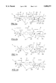
- FIGS. 1a, 1b, 1c and 1d are diagrammatic representations of a possible embodiment of the safety device according to the invention, illustrating different operating phases;
- FIG. 2 is a cross sectional view of the leak-type jack used as a delay member
- FIGS. 3a, 3b, 3c and 3d are diagrammatic representations of another possible embodiment of the separator device fitted with a locking system for the retaining stop, also illustrating different operating phases.
- the dynamic storage chute is constituted of a juxtaposition of cylinders 1 mounted to rotate freely on a horizontal axis 2.
- the cylinders 1 determine a raceway with a slight slope upstream towards downstream for the conveying and the storing of loads 3, 4, 5 such as pallets or boxes.
- the end of the dynamic storage chute is also fitted with a device enabling to separate the furthermost downstream load from the other loads. This device enables extraction of this end load without being disturbed by the thrust exerted by the other loads.
- This separator device is constituted of a pedal 8 arranged at the end of the chute and of a mobile stop 9 adapted to retain the second load as well as the following loads, by bearing upon the said.
- the retaining stop 9 is arranged at a distance from the end stop 7 greater than the length of a load.
- the pedal 8 is articulated round a rotational axis 10; it is actuated by the downstream load.
- the retaining stop 9 is articulated round a rotational axis 11; it has the shape of an end hook 12 connected to the said axis 11 via a tray 13. Beyond the axis 11, the stop 9 is prolonged by a manoeuvring arm 14 subject to actuation means and to de-actuation means.
- the actuation means of the stop 9 are constituted of a traction rod or tie 15 controlled by the end pedal 8.
- This tie 15 is articulated in 16 on the pedal 8; its upstream end traverses freely the arm 14 and co-operates in traction with the latter via a stop 20 which has, preferably, the shape of an adjustable screw.
- the pedal 8 has a direct effect on the stop 9, via the tie 15 and the arm 14.
- connection between the pedal 8 and the stop 9 involve articulated joints and the connection between the end of the tie 15 whose upstream end traverses freely in the arm 14 and cooperates in traction with the arm 14 via stop 20. Accordingly, the connection between the pedal 8 and the retaining stop 9, via tie 15, is substantially nonelastic.
- the de-actuation means of the retaining stop 9 consist of a counterweight or of a balancing spring 22 acting permanently on the manoeuvring arm 14, in reverse direction of the traction effect exerted by the rod 15 and its end stop 20.
- FIG. 1a represents the balancing spring option 22 as a straight line and the counterweight option as a dotted line.
- Such a separation device is more or less balanced round the articulation axis 11 in order to tend to bring the pedal 8 back into raised position and the stop 9 into inactive position.
- This device enables to set the stop 9 into active retaining position by the action of the end pedal 8, when the latter is controlled by the downstream load. Thanks to the balancing effect, this manoeuvre is performed with minimum encumbrance. Thus, even very light loads have sufficient kinetic energy to implement the separation device, which confers almost a general purpose character to the storage chute so fitted.
- the stop 9 is de-actuated when removing the downstream load to let the following load take its place at the end of the chute. This load then actuates itself the retaining stop 9 via the pedal 8 and the traction rod 15 in order to retain the other loads.
- Such a separator device provides the operator with some time to remove the end load before the arrival of the following load.
- the separation device according to the invention is fitted with means enabling to control the de-actuation motion of the retaining stop 9.
- control means take the shape of a delay member 25 which allows to retain the stop 9 in active position, beyond the moment when the downstream load ceases to be in contact with the end pedal 8. This delay, before de-actuation, is set to provide the operator with sufficient time, in relation to the installation and to the type of loads, to ensure removing and handling the downstream load, without worrying about the arrival of the next load at the end of the chute.
- This delay member 25 consists of a leak-type hydraulic jack, arranged under the stop 9 and which is detailed on FIG. 2.
- This leak-type jack 25 is constituted of a cylindrical body 26 enclosing a mobile plunger 27 which separates the said cylindrical body 26 into two chambers 28 and 29 filled or partially filled with oil.
- the cylindrical body 26 is arranged vertically; it is blanked off, at its base, by a bottom 30 and in its upper part, by an attached lid 31.
- the plunger 27 carries the jack's rod 32 which is centred on the axis of the cylindrical body 26. This rod 32 extends, protruding outside the cylindrical body 26, via an axial orifice 33 cut-out in the lid 31.
- the plunger 27 has the possibility of sliding axially in the cylindrical body 26; it is adjusted in the inner bore of the cylindrical body 26 with a slight clearance 34 which enables slight peripheral oil leak, from one chamber into another.
- the axial rod 32 and the plunger 27 are subject to a helicoidal spring 35 arranged outside the body of the jack 26.
- This spring 35 is placed round the rod 32; it bears, on one side, on a stop 36 arranged at the external end of the rod 32 and, on the other side, against the lid 31, on the rim of the axial orifice 33.
- the helicoidal spring 35 constitutes an inherent means tending to set the rod 32 in extracted position and to bring the plunger 27 back into the upper part of the cylindrical body 26.
- the plunger 27 is fitted with orifices 38 ensuring the connection between both chambers 28 and 29. These orifices 38 are associated with selective blank-off valves 39 arranged in the lower chamber 29 and interconnected with the plunger 27 via a ram 40.
- the valves 39 blank off the orifices 38 during the downward stroke of the plunger 27, thanks to the oil pressure inside the chamber 29; the downward stroke of the plunger 27 is then solely controlled by the peripheral clearance 34.
- valves 39 open and oil may flow freely from the chamber 28 into the chamber 29 via orifices 38.
- the motion of the plunger 27 is not controlled by the peripheral clearance 34 any longer and it has the possibility of going up more rapidly.
- two valves 39 are each associated with two orifices 38. To ensure the function just described, an orifice 38 and a valve 39 may be sufficient.
- FIG. 2 we notice the presence of an inner portion 41 with larger diameter, in the lower region of the cylindrical body 26.
- This portion 41 extends from a transition region 42 to the bottom 30. It is adapted to increase the peripheral clearance between the plunger 27 and the cylindrical body 26 in order, in this region, to limit or suppress the controlling or dampening effect of the plunger 27. This feature will be explained further below.
- FIGS. 1a to 1d Various operating phases of the separation device, rendered safe according to the invention, are illustrated on FIGS. 1a to 1d.
- FIG. 1a shows the downstream load 3 which is blocked by the end stop 7 and which actuates the pedal 8.
- the latter tracts the rod 15 which, itself, pulls the manoeuvring arm 14 via the stop 20.
- the strength exerted by the recall spring 22 is not sufficient to counter the weight of the load 3 on the pedal 8 and the hook 12 of the stop 9 is brought into active retaining position, above the raceway of the dynamic storage chute to block the second load 4 as well as those following it.
- the leak-type jack 25 is arranged under the stop 9 bearing against the frame of the storage chute; its rod 32 is in contact with the lower portion of the tray 13 and the plunger 27 is situated in the upper part of the cylindrical body 26.
- the leak-type jack 25 comes fully into effect as soon as contact ceases between the downstream load 3 and the pedal 8 in order to slow down or to dampen the de-actuation motion of the stop 9.
- the jack 25 controls the downward stroke of the stop 9 and delays the de-actuation of its end hook 12.
- the recall spring 22 exerts a traction onto the manoeuvring arm 14 which causes the tray 13 to bear against the end of the rod 32 of the jack 25
- the recall spring 35 of this jack 25 possesses a strength weaker than that of the recall spring 22 and the rod 32 engages progressively the cylindrical body 26 causing a downward motion of the plunger 27.
- This downward stroke is controlled by the slight peripheral clearance 34 down to the transition region 42.
- the valves 39 blank off the orifices 38; the peripheral clearance 34 is adapted to delay the de-actuation of the stop 9 according to a requested time, ranging from 5 seconds and 3 minutes, for instance.
- the rod 32 of the jack 25 comes back progressively and by itself to its extracted stable position thanks to the recall spring 35; this upward motion is accelerated by the opening of the valves 39.
- the actuation means of the retaining stop 9 (pedal 8, traction rod 15) are partially disconnected from the de-actuation means (recall spring 22) and the delay member 25 is arranged directly under the stop 9. While adhering to the same operating principle, in the installation described above or within the framework of different separation devices, the jack-like 25 delay system can be designed to co-operate with any member in motion (end pedal, connecting rod or other . . . ).
- the delay system must not interfere (or little) with the actuation of the retaining stop 9 by the pedal 8.
- FIGS. 3a to 3d we have kept a load separation system substantially balanced round the rotational axis of the retaining stop to enable its actuation by any load type.
- the separator in question comprises, moreover, a retaining stop's locking system to render operation safer. This locking system enables to avoid the removing or the de-actuation of the stop subject to the action of a heavy load or having a sizeable kinetic energy.
- the separation device picks up partially he same elements as that illustrated on FIGS. 1a to 1d. These elements keep the same item numbers for easy reference.
- the separation device properly speaking consists of a pedal 8 and of a mobile stop 9 linked by the tie 15.
- the stop 9 mounted on the articulation axis 11 is prolonged by a manoeuvring arm 14 which is subject to the action exerted by the balancing spring 22 and which is traversed by the rod 15 fitted with a stop 20 in the form of an adjustable screw.
- the stop's 9 locking sub-assembly is constituted of a lever 45 controlling the motion of a toggle joint 46 interconnected with the said stop 9.
- the lever 45 is articulated in 47 on the frame of the chute; it is located upstream of the pedal 8, at a distance from the former smaller than the length of the loads.
- This lever 45 comprises a protruding section which extends above the circulation plane of the loads and which is fitted with a roller system 48.
- the lever 45 controls the motion of the toggle joint 46 via a rod 50.
- the toggle joint 46 is constituted of two rocker bars 51 and 52 interposed between the frame of the chute and the retaining stop 9. Both rocker bars 51 and 52 are interconnected by an articulation axis 53. The other end of the rocker bar 51 is interconnected with the stop 9 via the articulation 54 and the other end of the rocker bar 52 is interconnected with the frame of the chute using the articulation 55.
- the rocker bar 51 comprises a lug-shaped extension 56 which serves as a guide for the rod 50 linked to the lever 45.
- the rod 50 goes through a suited orifice, arranged at the end of the lug 56 and it is fitted with an adjustable end stop 60; this link is located under the articulation 55 of the rocker bar 52 on the frame.
- the rod 50 is articulated at 61 on an extension from the lever 45.
- the rod 50 accommodates a welded square 62.
- This square 62 acts as a stop for a first accumulator member 63, in the form of a spring, which is mounted on the rod 50 and whose other end bears against the lug 56.
- This square 62 also serves as an anchor for a second accumulator member 64 whose other end is interconnected with the frame of the chute.
- the spring 63 is used for locking the toggle joint 46. In home position (toggle joint 46 de-actuated), this spring 63 is advantageously slightly compressed between the square 62 and the lug 56.
- the stiffness of the spring 63 may lie in the vicinity of 0.8 Newton/mm.
- the spring 64 exerts a traction effect on the rod 50; it is used for unlocking the toggle joint 46 and for bringing the lever 45 back into active position. With the toggle joint de-actuated, the spring 64 can be slightly stretched. The stiffness of the spring 64 may lie in the vicinity of 1.25 Newton/mm.
- the separator device and the locking sub-assembly are in inactive position.
- the pedal 8 and the lever 45 extend above the displacement plane of the loads.
- the retaining stop 9 is arranged under the displacement plane to allow the loads to move till the end of the chute.
- the lever 45 pivots round its articulation axis 47 which causes the rod 50 to move upstream of the chute, as well as the lug 66 to rise.
- the motion of the rod 50 charges the energy accumulators 63 and 64, compresses the spring 63 and stretches the spring 64.
- the spring 63 exerts a load onto the set of rocker bars 51 and 52.
- the load 67 continues its travel up to the end stop 7 (FIG. 3c) at the level of which it actuates the pedal 8 to bring the retaining stop 9 into active position to block the upstream loads 68.
- the rising of the stop 9 is accompanied by a motion of the toggle joint 46 assisted in so doing by the spring 63, thus giving back the energy accumulated.
- Both rocker bars 51 and 52 come apart to adopt a position more or less in the extension of one another, if not slightly beyond, in order to ensure efficient locking of the positioning of the stop 9.
- the pre-loaded spring 63 pushes against the lever arm 56 in order to assist and to complete this locking motion. As this motion is performed without any load, i.e. without any stress imposed on the stop 9, it is performed unrestricted and does not call for an excessive energy.
- the toggle joint 46 locks efficiently the retaining stop 9; this locking is suited to the maximum stress liable to be applied by the juxtaposition of the various loads 68.
- the new furthermost downstream load can move to the end of the chute and a new separation cycle starts again.
Landscapes
- Mechanical Engineering (AREA)
- Engineering & Computer Science (AREA)
- Forklifts And Lifting Vehicles (AREA)
- Spinning Or Twisting Of Yarns (AREA)
- Supplying Of Containers To The Packaging Station (AREA)
- Jib Cranes (AREA)
- De-Stacking Of Articles (AREA)
- Chutes (AREA)
- Closing And Opening Devices For Wings, And Checks For Wings (AREA)
- Warehouses Or Storage Devices (AREA)
- Polysaccharides And Polysaccharide Derivatives (AREA)
- Pharmaceuticals Containing Other Organic And Inorganic Compounds (AREA)
- Treatment Of Liquids With Adsorbents In General (AREA)
- Burglar Alarm Systems (AREA)
Applications Claiming Priority (3)
| Application Number | Priority Date | Filing Date | Title |
|---|---|---|---|
| FR9501195 | 1995-01-30 | ||
| FR9501195A FR2729936B1 (fr) | 1995-01-30 | 1995-01-30 | Systeme de securite pour dispositif de separation des charges dans un couloir de stockage dynamique |
| PCT/FR1996/000008 WO1996023714A1 (fr) | 1995-01-30 | 1996-01-03 | Separateur de charges pour couloir de stockage dynamique |
Publications (1)
| Publication Number | Publication Date |
|---|---|
| US5890577A true US5890577A (en) | 1999-04-06 |
Family
ID=9475760
Family Applications (1)
| Application Number | Title | Priority Date | Filing Date |
|---|---|---|---|
| US08/875,395 Expired - Lifetime US5890577A (en) | 1995-01-30 | 1996-01-03 | Load separator for a dynamic storage lane |
Country Status (8)
| Country | Link |
|---|---|
| US (1) | US5890577A (de) |
| EP (1) | EP0807081B1 (de) |
| AT (1) | ATE178019T1 (de) |
| AU (1) | AU4490496A (de) |
| DE (1) | DE69601864T2 (de) |
| ES (1) | ES2131387T3 (de) |
| FR (1) | FR2729936B1 (de) |
| WO (1) | WO1996023714A1 (de) |
Cited By (14)
| Publication number | Priority date | Publication date | Assignee | Title |
|---|---|---|---|---|
| US6119843A (en) * | 1999-02-03 | 2000-09-19 | Robinson; Brian Owen | Retractable stop assembly |
| US6189672B1 (en) * | 1999-02-08 | 2001-02-20 | Interroll Holding Ag | Rocker-type load separating mechanism for a roller conveyor |
| US6234292B1 (en) | 1999-08-04 | 2001-05-22 | Interroll Holding Ag | Pallet retainer for a conveyor |
| US6439369B1 (en) * | 2000-08-29 | 2002-08-27 | Edmund W. Brown | Flip-flop assembly for conveyor system |
| US20050011565A1 (en) * | 2002-01-24 | 2005-01-20 | Carl Seguin | Variable volume reservoir |
| EP1484265A3 (de) * | 2003-06-05 | 2005-05-18 | Fritz Schäfer GmbH | Vorrichtung zum Zurückhalten von auf einer geneigten Rollenbahn ablaufendem Transportgut |
| US20080006508A1 (en) * | 2006-06-26 | 2008-01-10 | American Sterilizer Company | Basket positioning system for multi-chamber washer |
| EP2517985A1 (de) * | 2011-04-28 | 2012-10-31 | Interroll Holding AG | Rollenförderermodul für ein schwerkraftbetriebenes Rollenförderersystem und Verfahren zur Geschwindigkeitskontrolle |
| CN102756896A (zh) * | 2011-04-26 | 2012-10-31 | 英特诺控股集团公司 | 延时分离器 |
| US20150021147A1 (en) * | 2012-03-28 | 2015-01-22 | Eton Innovation Ab | Guide rail part for a conveyor and a conveyor comprising such a guide rail part |
| EP3135616A1 (de) * | 2015-08-25 | 2017-03-01 | Interroll Holding AG | Förderer mit einem push-pull-mechanismus für einen lastentrenner |
| RU171994U1 (ru) * | 2017-03-31 | 2017-06-23 | федеральное государственное бюджетное образовательное учреждение высшего образования "Московский государственный технический университет имени Н.Э. Баумана (национальный исследовательский университет)" (МГТУ им. Н.Э. Баумана) | Устройство для остановки и разделения паллет роликовых гравитационных конвейеров |
| CN111545539A (zh) * | 2020-05-15 | 2020-08-18 | 烟台芝罘医院 | 一种医疗器械自动化清洗灭菌装置 |
| US11565891B2 (en) * | 2018-08-21 | 2023-01-31 | Euroroll GmbH | Actuating apparatus for actuating a separating device for a gravitational conveyor |
Families Citing this family (6)
| Publication number | Priority date | Publication date | Assignee | Title |
|---|---|---|---|---|
| FR2759684B1 (fr) * | 1997-02-20 | 1999-05-07 | Sipa Roller | Dispositif separateur a bascule pour couloir de stockage dynamique |
| EP1125820B2 (de) † | 2000-02-15 | 2012-07-11 | Nsk Ltd | Lenkung für ein Automobil |
| CN102862771A (zh) * | 2012-08-17 | 2013-01-09 | 无锡杰思物流设备有限公司 | 重力式滚筒输送机用安全分离器 |
| CN104891164B (zh) * | 2015-06-10 | 2017-05-24 | 广州华工环源绿色包装技术股份有限公司 | 一种输送线的有序放料机构 |
| EP3254997B1 (de) * | 2016-06-06 | 2019-03-06 | ALTRATEC Automation GmbH | Vorrichtung zum stoppen eines fördergutes auf einem förderer |
| CN113333293A (zh) * | 2021-05-11 | 2021-09-03 | 科捷智能科技股份有限公司 | 输送线料箱分离装置 |
Citations (5)
| Publication number | Priority date | Publication date | Assignee | Title |
|---|---|---|---|---|
| GB1009128A (en) * | 1963-01-18 | 1965-11-03 | Gemag Geraete Und Maschb Ag | Device for conveying goods loaded on pallets |
| DE7534405U (de) * | 1975-10-29 | 1977-03-10 | Dipl.-Ing. Otto Schulze-Berge Foerder- Und Lagertechnik, 4713 Bockum- Hoevel | Vorrichtung zum Trennen von Paletten auf einer Schwerkraftrollenbahn |
| FR2639331A1 (fr) * | 1988-11-18 | 1990-05-25 | Sipa Sa | Dispositif de separation de palettes pour couloir de stockage dynamique |
| US5213189A (en) * | 1992-05-26 | 1993-05-25 | Interroll Holding A.G. | Load separating mechanism for a roller conveyor |
| DE9404684U1 (de) * | 1994-03-19 | 1994-05-19 | Nedcon Magazijninrichting B.V., Doetinchem | Vorrichtung zum Zurückhalten von entlang einer Rollenbahn, insbesondere der Rollenbahn eines Durchlaufregals, verfahrbaren Gegenständen, z.B. Paletten |
-
1995
- 1995-01-30 FR FR9501195A patent/FR2729936B1/fr not_active Expired - Fee Related
-
1996
- 1996-01-03 US US08/875,395 patent/US5890577A/en not_active Expired - Lifetime
- 1996-01-03 AT AT96901012T patent/ATE178019T1/de not_active IP Right Cessation
- 1996-01-03 ES ES96901012T patent/ES2131387T3/es not_active Expired - Lifetime
- 1996-01-03 AU AU44904/96A patent/AU4490496A/en not_active Abandoned
- 1996-01-03 WO PCT/FR1996/000008 patent/WO1996023714A1/fr not_active Ceased
- 1996-01-03 DE DE69601864T patent/DE69601864T2/de not_active Expired - Lifetime
- 1996-01-03 EP EP96901012A patent/EP0807081B1/de not_active Expired - Lifetime
Patent Citations (5)
| Publication number | Priority date | Publication date | Assignee | Title |
|---|---|---|---|---|
| GB1009128A (en) * | 1963-01-18 | 1965-11-03 | Gemag Geraete Und Maschb Ag | Device for conveying goods loaded on pallets |
| DE7534405U (de) * | 1975-10-29 | 1977-03-10 | Dipl.-Ing. Otto Schulze-Berge Foerder- Und Lagertechnik, 4713 Bockum- Hoevel | Vorrichtung zum Trennen von Paletten auf einer Schwerkraftrollenbahn |
| FR2639331A1 (fr) * | 1988-11-18 | 1990-05-25 | Sipa Sa | Dispositif de separation de palettes pour couloir de stockage dynamique |
| US5213189A (en) * | 1992-05-26 | 1993-05-25 | Interroll Holding A.G. | Load separating mechanism for a roller conveyor |
| DE9404684U1 (de) * | 1994-03-19 | 1994-05-19 | Nedcon Magazijninrichting B.V., Doetinchem | Vorrichtung zum Zurückhalten von entlang einer Rollenbahn, insbesondere der Rollenbahn eines Durchlaufregals, verfahrbaren Gegenständen, z.B. Paletten |
Cited By (23)
| Publication number | Priority date | Publication date | Assignee | Title |
|---|---|---|---|---|
| US6119843A (en) * | 1999-02-03 | 2000-09-19 | Robinson; Brian Owen | Retractable stop assembly |
| US6189672B1 (en) * | 1999-02-08 | 2001-02-20 | Interroll Holding Ag | Rocker-type load separating mechanism for a roller conveyor |
| US6234292B1 (en) | 1999-08-04 | 2001-05-22 | Interroll Holding Ag | Pallet retainer for a conveyor |
| US6439369B1 (en) * | 2000-08-29 | 2002-08-27 | Edmund W. Brown | Flip-flop assembly for conveyor system |
| US20050011565A1 (en) * | 2002-01-24 | 2005-01-20 | Carl Seguin | Variable volume reservoir |
| US6981523B2 (en) * | 2002-01-24 | 2006-01-03 | Sobacor | Variable volume reservoir |
| EP1484265A3 (de) * | 2003-06-05 | 2005-05-18 | Fritz Schäfer GmbH | Vorrichtung zum Zurückhalten von auf einer geneigten Rollenbahn ablaufendem Transportgut |
| US20080006508A1 (en) * | 2006-06-26 | 2008-01-10 | American Sterilizer Company | Basket positioning system for multi-chamber washer |
| US7431141B2 (en) * | 2006-06-26 | 2008-10-07 | American Sterilizer Company | Basket positioning system for multi-chamber washer |
| CN102756896A (zh) * | 2011-04-26 | 2012-10-31 | 英特诺控股集团公司 | 延时分离器 |
| US20120273325A1 (en) * | 2011-04-26 | 2012-11-01 | Interroll Holding Ag | Time delay separator |
| US8820506B2 (en) * | 2011-04-26 | 2014-09-02 | Interroll Holding Ag | Time delay separator |
| EP2517985A1 (de) * | 2011-04-28 | 2012-10-31 | Interroll Holding AG | Rollenförderermodul für ein schwerkraftbetriebenes Rollenförderersystem und Verfahren zur Geschwindigkeitskontrolle |
| CN104321238B (zh) * | 2012-03-28 | 2017-02-22 | 伊顿创新有限公司 | 运输机用导引轨道件和包括导引轨道件的运输机 |
| CN104321238A (zh) * | 2012-03-28 | 2015-01-28 | 伊顿创新有限公司 | 运输机用导引轨道件和包括导引轨道件的运输机 |
| US9371075B2 (en) * | 2012-03-28 | 2016-06-21 | Eton Innovation Ab | Guide rail part for a conveyor and a conveyor including a guide rail part |
| US20150021147A1 (en) * | 2012-03-28 | 2015-01-22 | Eton Innovation Ab | Guide rail part for a conveyor and a conveyor comprising such a guide rail part |
| EP3135616A1 (de) * | 2015-08-25 | 2017-03-01 | Interroll Holding AG | Förderer mit einem push-pull-mechanismus für einen lastentrenner |
| WO2017032456A1 (en) * | 2015-08-25 | 2017-03-02 | Interroll Holding Ag | Conveyor with a push-pull mechanism for a load separator |
| US10273093B2 (en) | 2015-08-25 | 2019-04-30 | Interroll Holding Ag | Conveyor with a push-pull mechanism for a load separator |
| RU171994U1 (ru) * | 2017-03-31 | 2017-06-23 | федеральное государственное бюджетное образовательное учреждение высшего образования "Московский государственный технический университет имени Н.Э. Баумана (национальный исследовательский университет)" (МГТУ им. Н.Э. Баумана) | Устройство для остановки и разделения паллет роликовых гравитационных конвейеров |
| US11565891B2 (en) * | 2018-08-21 | 2023-01-31 | Euroroll GmbH | Actuating apparatus for actuating a separating device for a gravitational conveyor |
| CN111545539A (zh) * | 2020-05-15 | 2020-08-18 | 烟台芝罘医院 | 一种医疗器械自动化清洗灭菌装置 |
Also Published As
| Publication number | Publication date |
|---|---|
| DE69601864T2 (de) | 1999-11-11 |
| ES2131387T3 (es) | 1999-07-16 |
| FR2729936B1 (fr) | 1997-04-18 |
| EP0807081B1 (de) | 1999-03-24 |
| AU4490496A (en) | 1996-08-21 |
| FR2729936A1 (fr) | 1996-08-02 |
| ATE178019T1 (de) | 1999-04-15 |
| DE69601864D1 (de) | 1999-04-29 |
| EP0807081A1 (de) | 1997-11-19 |
| WO1996023714A1 (fr) | 1996-08-08 |
Similar Documents
| Publication | Publication Date | Title |
|---|---|---|
| US5890577A (en) | Load separator for a dynamic storage lane | |
| EP3180281B1 (de) | Förderer mit einem push-pull-mechanismus für einen lastentrenner | |
| US4615533A (en) | Method and apparatus for improved operation of pallet trucks | |
| CA2918269C (en) | Pallet dispenser and method thereof | |
| NO153067B (no) | Innretning for aa anbringe en offshore-plattform paa en baerekonstruksjon | |
| US20020110447A1 (en) | Cantilevered, self-adjusting pneumatic pallet positioner | |
| US4921385A (en) | Truck with a hand-operatable bed | |
| US3494440A (en) | Device for moving heavy objects up and down stairs | |
| US3034675A (en) | Carriage control for lift trucks | |
| US4212240A (en) | Trash compactor | |
| CA1146309A (en) | Dockboards | |
| CN111071896B (zh) | 一种电梯轿厢用缓冲保护装置 | |
| US4344354A (en) | Valve arrangement for controlling the stroke of a telescoping prop | |
| US3081470A (en) | Automatically operable ramp unit | |
| EP0055185A1 (de) | Vorrichtung zum Dämpfen der Stösse zwischen einer Last und einem schwimmenden Träger im Augenblick des Anhebens der Last | |
| FR2523110A1 (fr) | Dispositif de securite pour un pont elevateur hydraulique a deux colonnes | |
| CN223606274U (zh) | 一种易腐垃圾清理运输设备 | |
| CA2285958C (en) | Vacuum-relief valve for the floating roofs of tanks for storing liquids | |
| CN216549431U (zh) | 一种安全防护性高的液压升降机 | |
| KR930007430Y1 (ko) | 부스터 실린더를 이용한 포크리프트 안전장치 | |
| FR2701468A1 (fr) | Dispositif de levée à récupération d'énergie pour transpalette manuel ou cric. | |
| BE365523A (de) | ||
| JPH0582657U (ja) | ダンプ車の安全装置 | |
| WO2016009331A1 (en) | Multi-stack pallet dispensing apparatus | |
| BE529514A (de) |
Legal Events
| Date | Code | Title | Description |
|---|---|---|---|
| AS | Assignment |
Owner name: SIPA-ROLLER, FRANCE Free format text: ASSIGNMENT OF ASSIGNORS INTEREST;ASSIGNOR:FAISANT, GILLES;REEL/FRAME:008714/0602 Effective date: 19970722 |
|
| STCF | Information on status: patent grant |
Free format text: PATENTED CASE |
|
| FPAY | Fee payment |
Year of fee payment: 4 |
|
| REMI | Maintenance fee reminder mailed | ||
| FPAY | Fee payment |
Year of fee payment: 8 |
|
| FPAY | Fee payment |
Year of fee payment: 12 |