US5885488A - Column for counter-currently contacting gas and liquid - Google Patents
Column for counter-currently contacting gas and liquid Download PDFInfo
- Publication number
- US5885488A US5885488A US08/555,059 US55505995A US5885488A US 5885488 A US5885488 A US 5885488A US 55505995 A US55505995 A US 55505995A US 5885488 A US5885488 A US 5885488A
- Authority
- US
- United States
- Prior art keywords
- tray
- column
- liquid
- separation
- gas
- Prior art date
- Legal status (The legal status is an assumption and is not a legal conclusion. Google has not performed a legal analysis and makes no representation as to the accuracy of the status listed.)
- Expired - Lifetime
Links
Images

Classifications
-
- B—PERFORMING OPERATIONS; TRANSPORTING
- B01—PHYSICAL OR CHEMICAL PROCESSES OR APPARATUS IN GENERAL
- B01D—SEPARATION
- B01D3/00—Distillation or related exchange processes in which liquids are contacted with gaseous media, e.g. stripping
- B01D3/14—Fractional distillation or use of a fractionation or rectification column
- B01D3/16—Fractionating columns in which vapour bubbles through liquid
- B01D3/18—Fractionating columns in which vapour bubbles through liquid with horizontal bubble plates
- B01D3/20—Bubble caps; Risers for vapour; Discharge pipes for liquid
Definitions
- the invention relates to a normally vertical column for counter-currently contacting gas and liquid to exchange heat and/or matter between the gas and the liquid.
- the column In counter-currently contacting, gas flows upwards and liquid flows downwards through the column.
- the column is provided with a plurality of horizontal contact trays arranged axially spaced apart in the column, wherein each contact tray is provided with gas passages and a downcomer which opens below the contact tray.
- ⁇ downcomer ⁇ is used to refer to a conduit for downward transport of liquid from a tray, wherein the inlet end of the conduit is provided with a weir extending above the tray.
- the weir can be part of the downcomer or the weir can be separately arranged on the tray.
- the swirl tube is a cylindrical pipe in which swirl imparting means are arranged.
- gas with entrained liquid flows through the swirl tube and the swirl imparting means cause the gas to rotate; under influence of centrifugal forces, entrained liquid moves away from the center of the swirl tube and is collected on the inner surface of the cylindrical pipe where a film of liquid is formed.
- the liquid film breaks up and liquid droplets move away from the pipe; these liquid droplets should fall on the separation tray.
- the path of some of the liquid droplets will be such that they hit the contact tray above the separation tray, and they are entrained through the gas passages of that contact tray.
- the upper ends of the swirl tubes discharge straight into the gas passages of the contact tray above the separation tray, so that the gas flows towards the gas passages of the contact tray and the liquid hits the contact tray around the gas passages.
- the known separation tray comprises as many swirl tubes as there are gas passages in the next higher contact tray, and the diameter of the swirl tubes is equal to the diameter of the gas passages in the next higher contact tray.
- the layout of the swirl tubes is similar to the lay out of the gas passages, consequently the net free area of the known separation tray equals the net free area of the contact tray, wherein the net free area of the separation tray is the area of the passages in the swirl tubes divided by the active area of the separation tray, and wherein the net free area of the contact tray is the area of the gas passages divided by the active area of the contact tray.
- the column for counter-currently contacting gas and liquid provided with inlets and outlets for fluids, which column is provided with a plurality of horizontal contact trays arranged axially spaced apart in the column, each contact tray being provided with gas passages and a downcomer opening below the contact tray, and with a plurality of horizontal separation trays provided with swirl tubes and with means for removing liquid from the separation tray, each separation tray being arranged above a contact tray, wherein each swirl tube is provided with an annular U-turn deflector arranged over the upper end of the swirl tube.
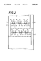
- FIGS. 1 and 2 show schematically cross-sectional views of part of a column 1 for counter-currently contacting gas and liquid according to two embodiments of the present invention.
- the column is provided with inlets and outlets for fluids.
- the position of the inlets and outlets depends on the use of the column: when the column is used to remove contaminants from a gas mixture by counter-currently contacting the gas mixture with an absorbent liquid, the column has a gas inlet and a liquid outlet arranged in its lower end and a liquid inlet and a gas outlet arranged in its upper end, and when the column is used for distilling a feed, the column has a feed inlet arranged near its middle part, a gas inlet and a liquid outlet arranged in its lower end and a liquid inlet and a gas outlet arranged in its upper end.
- a further advantage of the column according to the present invention is that the net free area of the separation tray is larger than the net free area of the known separation tray.
- the pressure drop over the separation tray is proportional to the gas velocity in the swirl tubes, and as this gas velocity is inversely proportional to the net free area, the pressure drop over the separation tray is smaller than the pressure drop over the known separation tray.
- FIGS. 1 and 2 showing schematically cross-sectional views of part of a column 1 for counter-currently contacting gas and liquid according to the present invention provided with horizontal contact trays 5, 6, 7 and 8 arranged axially spaced apart in the column 1.
- the horizontal contact trays 5, 6, 7 and 8 are so-called sieve trays.
- a sieve tray is a flat plate provided with holes in it; for the sake of clarity the holes in the plates have not been referred to by reference numerals.
- the horizontal contact trays 5, 6, 7 and 8 are provided with downcomers 10, 11, 12 and 13, respectively.
- the downcomer 10 opens below the contact tray 5 onto the next lower contact tray 6, and so on.
- the tray in which downcomer 13 opens is not shown, and in practice the downcomer pertaining to lowermost separation tray of the column will open into the lower part of the column.
- the column 1 is provided with a gas inlet and a liquid outlet arranged in its lower end and a liquid inlet and a gas outlet arranged in its upper end; the gas inlet, the liquid outlet, the liquid inlet and the gas outlet are not shown in the Figure.
- Column 1 is furthermore provided with horizontal separation trays 15, 16 and 17, each separation tray 15, 16 or 17 being arranged above a contact tray 6, 7 or 8.
- the separation trays 15, 16 and 17 are provided with swirl tubes 20, 21 and 22.
- the swirl tubes 20, 21 and 22 are internally provided with swirl imparting means 25, for example swirl vanes.
- Each separation tray 15, 16 or 17 is furthermore provided with means for removing liquid from the separation tray in the form of a downcomer 29, 30 and 31.
- the downcomer 29 of separation tray 15 opens via downcomer 11 on the second contact tray 7 below the separation tray 15, and so on. Please note that the second contact tray below separation tray 17 is not shown, and the separation tray above contact tray 5 is not shown either.
- Each swirl tube 20, 21 or 22 is provided with an annular U-turn deflector 34, 35 and 36, respectively, arranged over and extending to within the upper end of the swirl tube 20, 21 or 22.
- gas is supplied to the column 1 through the gas inlet at the lower end of the column 1 and liquid is supplied to the column 1 through the liquid inlet at the upper end of the column 1.
- gas and liquid are contacted on the horizontal contact trays 5, 6, 7 and 8 to exchange matter and or heat, and after contacting, liquid and gas are removed from the column 1 through the gas outlet at the upper part of column 1 and through the liquid outlet at the lower part of column 1.
- the performance of a column is determined by the maximum gas flow rate as a function of the liquid flow rate; wherein the maximum gas flow rate is the gas flow rate at which entrainment of liquid by the upwards flowing gas starts.
- the column 1 is provided with the separation trays 15, 16 and 17.
- the upwardly flowing gas with entrained liquid is subjected to a centrifugal motion and as a result a liquid is separated from gas.
- the separated liquid is collected on the inner surfaces of the swirl tubes 20, 21 and 22.
- the liquid will break away from the inner surfaces of the swirl tubes 20, 21 and 22.
- the U-turn deflectors 34, 35 and 36 direct the liquid which breaks away towards the floors of the separation trays 15, 16 and 17.
- the column was operated for liquid flow rates which corresponded to flow parameters in the range of from 0.05 to 0.15, wherein the flow parameter is defined as (L/G)*(rho l /rho g ) 1/2 .
- the load factor is defined as U g *(rho g /(rho l -rho g ) 1/2 .
- L is the liquid flow rate in m 3 /s
- G is the gas flow rate in m 3 /s
- rho l is the liquid density in kg/m 3
- rho g is the gas density in kg/m 3
- U g is the superficial gas velocity in m/s.
- the pressure drop over the combination of contact tray and separation tray was between 500 and 4000 Pa.
- the maximum load factor was about 0.12 to 0.10 for the same flow parameters, and the pressure drop was between 250 and 2000 Pa. Consequently the column according to the invention provides a high maximum load factor at the expense of a larger pressure drop.
- the surface area of the ring formed by the rim 40 of the U-turn deflector 34 and the outer surface of the swirl tube 20 is smaller than the surface area of the ring formed by the inner surface of the U-turn deflector 34 and the inner surface of the swirl tube 20 at the top 41 of the swirl tube 20.
- the opening of the U-turn deflector can be sealed by liquid present on the separation tray during normal operation.
- the outer wall 45 of the U-turn deflector 35 extends to below the top of the weir 47 of the downcomer 30.
- the swirl tube 22 is provided with a droplet catcher in the form of a widening ring 49 arranged at the gas outlet end of the U-turn deflector 36.
- the contact tray can be any suitable contact tray, for example a valve tray.
- liquid removed by the separation tray 15 was returned to the contact tray 7 below the contact tray 6 to which the separation tray 15 pertains; and this also applied to the other separation trays 16 and 17.
- at least part of the liquid separated by a separation tray can be returned to the contact tray to which the separation tray pertains. This can be done by using downcomer pipes arranged in openings in the separation tray, or by using one downcomer that opens on the contact tray below the separation tray.
Landscapes
- Chemical & Material Sciences (AREA)
- Chemical Kinetics & Catalysis (AREA)
- Vaporization, Distillation, Condensation, Sublimation, And Cold Traps (AREA)
- Gas Separation By Absorption (AREA)
- Physical Or Chemical Processes And Apparatus (AREA)
Priority Applications (12)
| Application Number | Priority Date | Filing Date | Title |
|---|---|---|---|
| AU20723/95A AU684157B2 (en) | 1994-03-24 | 1995-03-21 | Column for counter-currently contacting gas and liquid |
| BR9507154A BR9507154A (pt) | 1994-03-24 | 1995-03-21 | Coluna para contatar gás e líquido em contracorrente |
| EP95913150A EP0751808B1 (en) | 1994-03-24 | 1995-03-21 | Column for counter-currently contacting gas and liquid |
| CA002186119A CA2186119C (en) | 1994-03-24 | 1995-03-21 | Column for counter-currently contacting gas and liquid |
| NZ282814A NZ282814A (en) | 1994-03-24 | 1995-03-21 | Column with horizontal contact trays and overlying separation trays having swirl tubes and annular deflectors |
| CZ19962655A CZ287116B6 (en) | 1994-03-24 | 1995-03-21 | Column for gas and liquid contacting each other in countercurrent flow |
| CN95192234A CN1048643C (zh) | 1994-03-24 | 1995-03-21 | 气液逆流接触塔 |
| PL95316385A PL177798B1 (pl) | 1994-03-24 | 1995-03-21 | Kolumna do przeciwbieżnego kontaktowania gazu i cieczy |
| PCT/EP1995/001078 WO1995025571A1 (en) | 1994-03-24 | 1995-03-21 | Column for counter-currently contacting gas and liquid |
| JP52439395A JP3787153B2 (ja) | 1994-03-24 | 1995-03-21 | 気体と液体とを向流接触させる塔 |
| US08/555,059 US5885488A (en) | 1994-03-24 | 1995-11-08 | Column for counter-currently contacting gas and liquid |
| NO19963986A NO316211B1 (no) | 1994-03-24 | 1996-09-23 | Kolonne for motströmskontakt mellom gass og v¶ske |
Applications Claiming Priority (2)
| Application Number | Priority Date | Filing Date | Title |
|---|---|---|---|
| EP94200775 | 1994-03-24 | ||
| US08/555,059 US5885488A (en) | 1994-03-24 | 1995-11-08 | Column for counter-currently contacting gas and liquid |
Publications (1)
| Publication Number | Publication Date |
|---|---|
| US5885488A true US5885488A (en) | 1999-03-23 |
Family
ID=26136112
Family Applications (1)
| Application Number | Title | Priority Date | Filing Date |
|---|---|---|---|
| US08/555,059 Expired - Lifetime US5885488A (en) | 1994-03-24 | 1995-11-08 | Column for counter-currently contacting gas and liquid |
Country Status (12)
| Country | Link |
|---|---|
| US (1) | US5885488A (ja) |
| EP (1) | EP0751808B1 (ja) |
| JP (1) | JP3787153B2 (ja) |
| CN (1) | CN1048643C (ja) |
| AU (1) | AU684157B2 (ja) |
| BR (1) | BR9507154A (ja) |
| CA (1) | CA2186119C (ja) |
| CZ (1) | CZ287116B6 (ja) |
| NO (1) | NO316211B1 (ja) |
| NZ (1) | NZ282814A (ja) |
| PL (1) | PL177798B1 (ja) |
| WO (1) | WO1995025571A1 (ja) |
Cited By (20)
| Publication number | Priority date | Publication date | Assignee | Title |
|---|---|---|---|---|
| US5981796A (en) * | 1997-02-25 | 1999-11-09 | Shell Oil Company | Process for the manufacture of carboxylic acids |
| WO2002034350A1 (en) * | 2000-10-23 | 2002-05-02 | Shell Internationale Research Maatschappij B.V. | Column for counter-currently contacting vapour and liquid |
| DE10203323C1 (de) * | 2002-01-29 | 2003-10-30 | Klaus Hartmann | Hochflexibler Stoffaustaschapparat |
| US6682633B1 (en) | 2000-12-22 | 2004-01-27 | Uop Llc | Apparatus for cocurrent fractional distillation |
| US20040104493A1 (en) * | 1997-11-19 | 2004-06-03 | Buchanan John Scott | Vapor/liquid contacting cyclone with secondary vanes |
| US20040195706A1 (en) * | 2003-02-21 | 2004-10-07 | Gerrit Konijn | Separation tray |
| US20070137482A1 (en) * | 2005-12-16 | 2007-06-21 | Zhanping Xu | Co-current vapor-liquid contacting apparatus |
| US20070145612A1 (en) * | 2003-12-22 | 2007-06-28 | Gerrit Konijn | Gas-liquid contacting tray |
| US20080156746A1 (en) * | 2006-12-14 | 2008-07-03 | Ludovic Raynal | Deflecting system for column trays |
| US20090115076A1 (en) * | 2004-11-30 | 2009-05-07 | Alexey Feofilaktovich Makhotkin | Vortex Apparatus With Descending Flow Of Phases |
| RU2498839C1 (ru) * | 2012-05-02 | 2013-11-20 | Открытое акционерное общество "Научно-исследовательский и проектный институт по переработке газа" (ОАО "НИПИгазпереработка") | Массообменный сепарационный элемент (варианты) и массообменная колонна (варианты) |
| US20150352462A1 (en) * | 2013-01-16 | 2015-12-10 | Sulzer Chemtech Ag | Hybrid Contact Tray for a Mass Transfer Column |
| USD816188S1 (en) | 2016-06-07 | 2018-04-24 | Koch-Glitsch, Lp | Tray valve cover |
| USD816189S1 (en) | 2016-06-07 | 2018-04-24 | Koch-Glitsch, Lp | Tray valve |
| RU2671733C1 (ru) * | 2018-01-31 | 2018-11-06 | Руслан Ильдарович Салимгареев | Устройство для сепарации газожидкостной смеси |
| RU2672420C1 (ru) * | 2018-01-31 | 2018-11-14 | Руслан Ильдарович Салимгареев | Устройство для сепарации газожидкостной смеси |
| RU2674948C1 (ru) * | 2018-02-02 | 2018-12-13 | Руслан Ильдарович Салимгареев | Устройство для сепарации газожидкостной смеси |
| US10258936B2 (en) | 2015-07-08 | 2019-04-16 | Koch-Glitsch, Lp | Contact tray for a mass transfer column |
| US20190299138A1 (en) * | 2018-03-29 | 2019-10-03 | Uop Llc | Vapor-liquid contacting apparatus and process with downcomer at shell |
| RU2818428C1 (ru) * | 2023-03-28 | 2024-05-02 | Валентин Николаевич Косенков | Центробежно-вихревая термодинамическая установка сепарационной очистки газообразных продуктов |
Families Citing this family (7)
| Publication number | Priority date | Publication date | Assignee | Title |
|---|---|---|---|---|
| US5683629A (en) * | 1995-06-02 | 1997-11-04 | Shell Oil Company | Horizontal tray and column for contacting gas and liquid |
| US5683493A (en) * | 1996-07-19 | 1997-11-04 | Stober; Berne K. | Packing for separation columns and process of use |
| US6214219B1 (en) | 1999-02-17 | 2001-04-10 | Calvcs, Llc | Knock-down separation of emulsions |
| US7004988B2 (en) | 2001-03-19 | 2006-02-28 | Shell Oil Company | Gas-liquid separator |
| JP3884343B2 (ja) * | 2002-07-18 | 2007-02-21 | タイコエレクトロニクスアンプ株式会社 | カード用コネクタ組立体 |
| KR101709754B1 (ko) | 2016-05-16 | 2017-02-23 | 베니트엠 주식회사 | 기체분배장치 및 기체 분배비율을 조절하는 방법 |
| CN112604430A (zh) * | 2020-11-23 | 2021-04-06 | 泰州市环宇复合材料有限公司 | 一种环保机械喷淋除尘装置 |
Citations (6)
| Publication number | Priority date | Publication date | Assignee | Title |
|---|---|---|---|---|
| US1983762A (en) * | 1933-09-12 | 1934-12-11 | Meinhard H Kotzebue | Fractionating apparatus |
| US3498028A (en) * | 1966-06-22 | 1970-03-03 | Shell Oil Co | Apparatus for contacting liquids and gases |
| US3605388A (en) * | 1967-12-29 | 1971-09-20 | Shell Oil Co | Apparatus for contacting luquids and gases |
| US3788045A (en) * | 1971-09-13 | 1974-01-29 | Peabody Engineering Corp | Gas cleaning apparatus |
| US4752307A (en) * | 1986-01-21 | 1988-06-21 | Shell Oil Company | Contacting gas and liquid |
| US4880451A (en) * | 1988-03-03 | 1989-11-14 | Shell Oil Company | Gas/liquid contacting apparatus |
Family Cites Families (3)
| Publication number | Priority date | Publication date | Assignee | Title |
|---|---|---|---|---|
| DD109806A1 (ja) * | 1973-07-09 | 1974-11-20 | ||
| US5300132A (en) * | 1992-03-25 | 1994-04-05 | Shell Oil Company | Contacting device |
| EP0694325A1 (en) * | 1994-07-29 | 1996-01-31 | Shell Internationale Researchmaatschappij B.V. | Column for contacting gas and liquid |
-
1995
- 1995-03-21 PL PL95316385A patent/PL177798B1/pl not_active IP Right Cessation
- 1995-03-21 WO PCT/EP1995/001078 patent/WO1995025571A1/en active IP Right Grant
- 1995-03-21 AU AU20723/95A patent/AU684157B2/en not_active Ceased
- 1995-03-21 EP EP95913150A patent/EP0751808B1/en not_active Expired - Lifetime
- 1995-03-21 CA CA002186119A patent/CA2186119C/en not_active Expired - Fee Related
- 1995-03-21 CN CN95192234A patent/CN1048643C/zh not_active Expired - Fee Related
- 1995-03-21 JP JP52439395A patent/JP3787153B2/ja not_active Expired - Fee Related
- 1995-03-21 NZ NZ282814A patent/NZ282814A/en not_active IP Right Cessation
- 1995-03-21 BR BR9507154A patent/BR9507154A/pt not_active IP Right Cessation
- 1995-03-21 CZ CZ19962655A patent/CZ287116B6/cs not_active IP Right Cessation
- 1995-11-08 US US08/555,059 patent/US5885488A/en not_active Expired - Lifetime
-
1996
- 1996-09-23 NO NO19963986A patent/NO316211B1/no not_active IP Right Cessation
Patent Citations (6)
| Publication number | Priority date | Publication date | Assignee | Title |
|---|---|---|---|---|
| US1983762A (en) * | 1933-09-12 | 1934-12-11 | Meinhard H Kotzebue | Fractionating apparatus |
| US3498028A (en) * | 1966-06-22 | 1970-03-03 | Shell Oil Co | Apparatus for contacting liquids and gases |
| US3605388A (en) * | 1967-12-29 | 1971-09-20 | Shell Oil Co | Apparatus for contacting luquids and gases |
| US3788045A (en) * | 1971-09-13 | 1974-01-29 | Peabody Engineering Corp | Gas cleaning apparatus |
| US4752307A (en) * | 1986-01-21 | 1988-06-21 | Shell Oil Company | Contacting gas and liquid |
| US4880451A (en) * | 1988-03-03 | 1989-11-14 | Shell Oil Company | Gas/liquid contacting apparatus |
Cited By (31)
| Publication number | Priority date | Publication date | Assignee | Title |
|---|---|---|---|---|
| US5981796A (en) * | 1997-02-25 | 1999-11-09 | Shell Oil Company | Process for the manufacture of carboxylic acids |
| US20040104493A1 (en) * | 1997-11-19 | 2004-06-03 | Buchanan John Scott | Vapor/liquid contacting cyclone with secondary vanes |
| US20050001336A1 (en) * | 1997-11-19 | 2005-01-06 | Buchanan John Scott | Vapor/liquid contacting cyclone with secondary vanes |
| US6877725B2 (en) * | 1997-11-19 | 2005-04-12 | Mobil Oil Corporation | Vapor/liquid contacting cyclone with secondary vanes |
| WO2002034350A1 (en) * | 2000-10-23 | 2002-05-02 | Shell Internationale Research Maatschappij B.V. | Column for counter-currently contacting vapour and liquid |
| US20040026801A1 (en) * | 2000-10-23 | 2004-02-12 | Gerrit Konijn | Column for counter-currently contacting vapour and liquid |
| US6905112B2 (en) | 2000-10-23 | 2005-06-14 | Shell Oil Company | Column for counter-currently contacting vapor and liquid |
| US6682633B1 (en) | 2000-12-22 | 2004-01-27 | Uop Llc | Apparatus for cocurrent fractional distillation |
| DE10203323C1 (de) * | 2002-01-29 | 2003-10-30 | Klaus Hartmann | Hochflexibler Stoffaustaschapparat |
| US20040195706A1 (en) * | 2003-02-21 | 2004-10-07 | Gerrit Konijn | Separation tray |
| US7841585B2 (en) | 2003-02-21 | 2010-11-30 | Shell Oil Company | Separation tray |
| US7510173B2 (en) | 2003-12-22 | 2009-03-31 | Shell-Oil Company | Gas-liquid contacting tray |
| US20070145612A1 (en) * | 2003-12-22 | 2007-06-28 | Gerrit Konijn | Gas-liquid contacting tray |
| US20090115076A1 (en) * | 2004-11-30 | 2009-05-07 | Alexey Feofilaktovich Makhotkin | Vortex Apparatus With Descending Flow Of Phases |
| US7424999B2 (en) | 2005-12-16 | 2008-09-16 | Uop Llc | Co-current vapor-liquid contacting apparatus |
| US20070137482A1 (en) * | 2005-12-16 | 2007-06-21 | Zhanping Xu | Co-current vapor-liquid contacting apparatus |
| US20080156746A1 (en) * | 2006-12-14 | 2008-07-03 | Ludovic Raynal | Deflecting system for column trays |
| US8128072B2 (en) * | 2006-12-14 | 2012-03-06 | Ifp | Deflecting system for column trays |
| US8313092B2 (en) | 2006-12-14 | 2012-11-20 | Ifp | Deflecting system for column trays |
| RU2498839C1 (ru) * | 2012-05-02 | 2013-11-20 | Открытое акционерное общество "Научно-исследовательский и проектный институт по переработке газа" (ОАО "НИПИгазпереработка") | Массообменный сепарационный элемент (варианты) и массообменная колонна (варианты) |
| US20150352462A1 (en) * | 2013-01-16 | 2015-12-10 | Sulzer Chemtech Ag | Hybrid Contact Tray for a Mass Transfer Column |
| US9987566B2 (en) * | 2013-01-16 | 2018-06-05 | Sulzer Chemtech Ag | Hybrid contact tray for a mass transfer column |
| US10258936B2 (en) | 2015-07-08 | 2019-04-16 | Koch-Glitsch, Lp | Contact tray for a mass transfer column |
| USD816188S1 (en) | 2016-06-07 | 2018-04-24 | Koch-Glitsch, Lp | Tray valve cover |
| USD816189S1 (en) | 2016-06-07 | 2018-04-24 | Koch-Glitsch, Lp | Tray valve |
| RU2671733C1 (ru) * | 2018-01-31 | 2018-11-06 | Руслан Ильдарович Салимгареев | Устройство для сепарации газожидкостной смеси |
| RU2672420C1 (ru) * | 2018-01-31 | 2018-11-14 | Руслан Ильдарович Салимгареев | Устройство для сепарации газожидкостной смеси |
| RU2674948C1 (ru) * | 2018-02-02 | 2018-12-13 | Руслан Ильдарович Салимгареев | Устройство для сепарации газожидкостной смеси |
| US20190299138A1 (en) * | 2018-03-29 | 2019-10-03 | Uop Llc | Vapor-liquid contacting apparatus and process with downcomer at shell |
| US11786855B2 (en) * | 2018-03-29 | 2023-10-17 | Uop Llc | Vapor-liquid contacting apparatus and process with downcomer at shell |
| RU2818428C1 (ru) * | 2023-03-28 | 2024-05-02 | Валентин Николаевич Косенков | Центробежно-вихревая термодинамическая установка сепарационной очистки газообразных продуктов |
Also Published As
| Publication number | Publication date |
|---|---|
| CZ265596A3 (en) | 1997-05-14 |
| AU2072395A (en) | 1995-10-09 |
| CA2186119C (en) | 2007-01-02 |
| CA2186119A1 (en) | 1995-09-28 |
| NO316211B1 (no) | 2003-12-29 |
| WO1995025571A1 (en) | 1995-09-28 |
| PL316385A1 (en) | 1997-01-06 |
| BR9507154A (pt) | 1997-09-02 |
| PL177798B1 (pl) | 2000-01-31 |
| EP0751808B1 (en) | 2000-03-08 |
| CN1151124A (zh) | 1997-06-04 |
| JP3787153B2 (ja) | 2006-06-21 |
| JPH09510395A (ja) | 1997-10-21 |
| AU684157B2 (en) | 1997-12-04 |
| NO963986D0 (no) | 1996-09-23 |
| NO963986L (no) | 1996-11-15 |
| NZ282814A (en) | 1997-07-27 |
| CZ287116B6 (en) | 2000-09-13 |
| CN1048643C (zh) | 2000-01-26 |
| EP0751808A1 (en) | 1997-01-08 |
Similar Documents
| Publication | Publication Date | Title |
|---|---|---|
| US5885488A (en) | Column for counter-currently contacting gas and liquid | |
| JP2967401B2 (ja) | 高効率活性領域増加装置 | |
| EP0828543B1 (en) | Horizontal tray and column for contacting gas and liquid | |
| US3233879A (en) | Fixed centrifugal gas and liquid contacting device | |
| JPH09173805A (ja) | 充填カラム用の改良された液体分配器 | |
| JPH08332374A (ja) | 多重下降管高性能トレー組立体 | |
| US4002432A (en) | Vapor-liquid separator | |
| US5106544A (en) | Method of and apparatus for vapor distribution | |
| US5300132A (en) | Contacting device | |
| EP0328786A1 (en) | Splash plate liquid distributor | |
| US20010015136A1 (en) | Column for counter-currently contacting gas and liquid | |
| CA3049746A1 (en) | Contact tray having baffle wall for concentrating low liquid flow and method involving same | |
| US6877725B2 (en) | Vapor/liquid contacting cyclone with secondary vanes | |
| US6905112B2 (en) | Column for counter-currently contacting vapor and liquid | |
| WO1999003554A1 (en) | Venturi swirl tube for vapor liquid contact tray | |
| US2753949A (en) | Benzol spray scrubber | |
| US2675215A (en) | Benzol spray scrubber | |
| AU686441B2 (en) | Column for contacting gas and liquid | |
| JP2007515280A (ja) | 気液接触トレイ | |
| GB2145012A (en) | Gas/liquid contact apparatus | |
| SU876144A2 (ru) | Кожухотрубный колонный аппарат |
Legal Events
| Date | Code | Title | Description |
|---|---|---|---|
| AS | Assignment |
Owner name: SHELL OIL COMPANY, TEXAS Free format text: ASSIGNMENT OF ASSIGNORS INTEREST;ASSIGNOR:KONIJN, GERRIT;REEL/FRAME:008381/0900 Effective date: 19951023 |
|
| STCF | Information on status: patent grant |
Free format text: PATENTED CASE |
|
| FEPP | Fee payment procedure |
Free format text: PAYOR NUMBER ASSIGNED (ORIGINAL EVENT CODE: ASPN); ENTITY STATUS OF PATENT OWNER: LARGE ENTITY |
|
| FPAY | Fee payment |
Year of fee payment: 4 |
|
| FPAY | Fee payment |
Year of fee payment: 8 |
|
| REMI | Maintenance fee reminder mailed | ||
| FPAY | Fee payment |
Year of fee payment: 12 |
|
| SULP | Surcharge for late payment |
Year of fee payment: 11 |