US5868110A - Crankcase for a piston machine - Google Patents
Crankcase for a piston machine Download PDFInfo
- Publication number
- US5868110A US5868110A US08/888,079 US88807997A US5868110A US 5868110 A US5868110 A US 5868110A US 88807997 A US88807997 A US 88807997A US 5868110 A US5868110 A US 5868110A
- Authority
- US
- United States
- Prior art keywords
- bearing
- crankcase
- wall
- bearing support
- rib
- Prior art date
- Legal status (The legal status is an assumption and is not a legal conclusion. Google has not performed a legal analysis and makes no representation as to the accuracy of the status listed.)
- Expired - Fee Related
Links
Images


Classifications
-
- F—MECHANICAL ENGINEERING; LIGHTING; HEATING; WEAPONS; BLASTING
- F16—ENGINEERING ELEMENTS AND UNITS; GENERAL MEASURES FOR PRODUCING AND MAINTAINING EFFECTIVE FUNCTIONING OF MACHINES OR INSTALLATIONS; THERMAL INSULATION IN GENERAL
- F16M—FRAMES, CASINGS OR BEDS OF ENGINES, MACHINES OR APPARATUS, NOT SPECIFIC TO ENGINES, MACHINES OR APPARATUS PROVIDED FOR ELSEWHERE; STANDS; SUPPORTS
- F16M1/00—Frames or casings of engines, machines or apparatus; Frames serving as machinery beds
- F16M1/02—Frames or casings of engines, machines or apparatus; Frames serving as machinery beds for reciprocating engines or similar machines
- F16M1/021—Frames or casings of engines, machines or apparatus; Frames serving as machinery beds for reciprocating engines or similar machines for housing crankshafts
-
- F—MECHANICAL ENGINEERING; LIGHTING; HEATING; WEAPONS; BLASTING
- F02—COMBUSTION ENGINES; HOT-GAS OR COMBUSTION-PRODUCT ENGINE PLANTS
- F02F—CYLINDERS, PISTONS OR CASINGS, FOR COMBUSTION ENGINES; ARRANGEMENTS OF SEALINGS IN COMBUSTION ENGINES
- F02F7/00—Casings, e.g. crankcases or frames
- F02F7/0043—Arrangements of mechanical drive elements
- F02F7/0053—Crankshaft bearings fitted in the crankcase
Definitions
- the invention relates to a crankcase for a piston engine or piston compressor including a bearing support structure for supporting a divided crankshaft main bearing which has a bearing part formed integrally with the bearing support structure and a bearing cover bolted to the bearing part.
- crankcase for a piston internal combustion engine including bearing support structures for mounting divided main bearings of a crankshaft and a crankshaft casing wall extending down below the crankshaft axis and connected to the bearing support structures above the crankshaft axis.
- the main bearing of the crankshaft comprises a bearing half disposed in the bearing support structure and a bearing cover bolted to the bearing support structure by bearing bolts screwed into heavy-walled threaded bolt holes.
- the rigidity of the crankcase, or respectively, the bearing support structure is achieved by an accumulation of wall material in the area of the bolt mounting structures and the joint area between the crankcase wall and the bolt mounting structure adjacent the bearing support structure at the end remote from the crankshaft bearing and by providing reinforcement ribs on the outside of the crankcase wall and the bearing support structure.
- the utilization of such a large amount of material is contradictory to the need for light-weight crankcases.
- crankcase for a multi-cylinder piston type internal combustion engine with walls which extend transversely to the longitudinal engine axis and which support each a divided main bearing for the crankshaft.
- the main bearing consists of a bearing base portion associated with the wall and a bearing cover which is mounted onto the bearing base portion by bolts which are screwed into heavy walled bolt mounting columns.
- the crankcase wall extends down to an area below the crankshaft axis to about the level of the bolt heads and is connected to the bearing base portion by means of a web extending about at the level of the dividing plane of the main bearing.
- the piston forces of the engine transmitted from the crankshaft to the main bearings are transferred to the crankcase through the bolt mounting columns in various areas of the wall which includes the main bearings.
- the location of these areas depend on the size of the transverse component of the piston force vector. Consequently, the rigidity of the crankcase is determined by the wall thickness of the walls supporting the main bearings. These walls must be quite strong and consequently heavy in order to provide the rigidity needed for the bolt mounting columns and the bolts received therein to remain unaffected by the transverse component of the piston force vector.
- crankcase which has a relatively low weight but is still capable of withstanding relatively high dynamic loads.
- the bearing support structure includes a transverse wall which extends between the crankcase walls, the bearing support base and the bearing base part and includes a rib structure of an increased wall thickness formed between the bearing base part and the bearing support base and having a recess in the area between the end of a mounting bolt bore in the bolt mounting column and the bearing support base providing for a force flux path evenly distributing the force flux over the length of the threaded mounting bolt bore area.
- the recesses in the rib structures form rib legs through which the piston forces are transferred from the crankshaft main bearing of the piston machine to the bearing base structure.
- a threaded bore extends into the bolt mounting column for receiving a bearing bolt which bore is directed toward the bearing base structure opposite the bolt mounting column. This provides for an even load distribution of the thread of the bolted connection when loads are applied during operation of the piston machine.
- the end of the rib structure becomes wider toward the bearing such that the rib structure is connected to the bearing base structure beginning at the separation plane over an arc area of 50° to 80°.
- the rib structure has a wide support base with a relatively small amount of material because of the recesses on the opposite sides whereby the stiffness of the bearing support structure with respect to the transverse components of the piston forces effective during operation of the piston machine is substantially increased. If the rib structure becomes wider in the form of convex curves with respect to the longitudinal extension of the rib structure, the rib structure is subjected to homogenous flux forces, while material in areas, which are not subjected to a force flux, is eliminated.
- the recesses on both sides of the rib structure have the same shape and are arranged opposite one another and the rib is contoured on both sides of the recess.
- the recesses are essentially drop shaped or oval whereby the force fluxes on opposite sides of the recesses are combined at the longitudinal ends of the recesses to homogeneous force fluxes.
- the recess is rounded and the force flux converges into the bolt mounting column such that the thread of the bearing bolt disposed in the bolt mounting column is evenly loaded.
- the bottom of the recess has a minimal wall thickness, which at most has the thickness of the transverse wall from which the rib structure projects. If the recess bottom wall is disposed in the same plane as the transverse wall and the opposite sides of the rib structure are disposed at the same distance from the transverse wall, the force flux conditions are essentially homogenous.
- the areas of the recess adjacent the bolt are rounded, the opposite end area is pointed, and they are disposed along a line following the force input and force transfer to the bearing support base during operation of the piston machine. Furthermore, at least in the opposite end areas, the walls defining the recess are inclined or rounded to avoid stress peaks in the material.
- the transverse wall has several webs which extend between the rib structure and the crankcase wall and which project about to the level of the side walls of the rib structure.
- force transmission structures are formed by the relatively rigid webs in connection with the relatively thin transverse wall which provide for a good support for the main bearing at the crankcase wall and increase the rigidity of the bearing support structure.
- the arrangement utilizes a relatively small amount of material and is therefore relatively light-weight.
- an upper web extending about at level of the rounded end of the recess, an intermediate web extending about at the level of the separation plane of the main bearing adjacent the bolt mounting column and a lower web extending from the area of the intermediate web adjacent the main bearing to the open end of the crankcase wall.
- the upper and the intermediate webs are essentially parallel to the separation plane of the main bearing whereby the shape of the force transmission areas is rectangular and they have a high rigidity for force flux paths which extend essentially at right angles to one another.
- the wall may have an opening whereby ventilation in the crankcase of the piston machine is improved and, furthermore, weight is saved.
- the opening is preferably elliptical or oval and extends about in the direction of the force flux.
- bearing support structure is cast as a single component whereby mass production costs are relatively low.
- crankcase according to the invention An embodiment of the crankcase according to the invention will be described below in greater detail on the basis of the accompanying drawings.
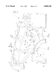
- FIG. 1 is a perspective, partially sectional view of a crankcase bearing support structure.
- FIG. 2 is a view of the bearing support structure turned by about 180° from that shown in FIG. 1 showing the force lines effective under a piston load.
- FIG. 3 is a view like that of FIG. 2 showing the force lines effective upon mounting of the bearing cover
- FIG. 4 is a cross-sectional view taken along line IV--IV of FIG. 1,
- FIG. 5 is a cross-sectional view taken along line V--V of FIG. 1, and
- FIG. 6 is a cross-sectional view taken along line VI--VI of FIG. 1.
- the bearing support structure as shown in FIG. 1 serves to support a divided main bearing 2 for a crankshaft in a crankcase.
- the main bearing 2 which is divided along a separation plane 6 consists of a bearing base part 3 associated with the bearing support structure 1 and a bearing cover 4 bolted onto the bearing support structure 1.
- the main bearing 2 is connected by a transverse wall 9 to a side wall 7 and to a bearing support base 8 of the crankcase.
- the transverse wall 9 is provided with a rib structure 12 which interconnects the bearing base part 3 and the bearing support base 8.
- the rib structure 12 becomes wider toward the main bearing 2 in the form of arcs which extend convexly in the longitudinal direction of the rib structure and are connected from the separation plane 6 on with the bearing part 3 over an arc angle of about 75°.
- the front side 13 of the rib structure 12 which projects from the transverse wall 9 in a mirror symmetric fashion includes a drop-shaped recess 15 which has a pointed end 18 adjacent the bearing support base and a rounded end 19 adjacent the main bearing 2.
- a recesses 15 formed in the rib structure 12 at both sides of the transverse wall 9 and a recess wall 17 having a small wall thickness disposed in the recesses essentially convexly extending rib legs 26, 27 are formed which transfer the force flux generated by the piston forces of the piston machine and which enters the rib legs 26, 27 from the bearing support structure.
- the recess 15 is disposed about centrally between the rib legs 26, 27 such that the rounded end 19 of the recess 15 is disposed about at the level of the jointure of the inner rib leg 27 with the bearing base part 3 and at a small distance from the end of the threaded bore receiving a bearing bolt (see FIG. 2). In this manner, the force flux into the thread can be controlled by the arched shape of the rib legs 26, 27 in a way as will be described below with reference to FIG. 2.
- the transverse wall 9 is provided with webs 20, 21, 22, which project from the wall 9 in a mirror symmetrical fashion with respect to the wall 9 up to the level of the front side 13 of the rib structure 12.
- An upper web 20 is disposed about at the level of the rounded end of the recess 15 and extends parallel to the separation plane 6 of the main bearing 2
- an intermediate web 21 which is also parallel to the separation plane 6 of the main bearing extends between the bottom area of the rib structure 12 adjacent the bearing separation plane and the crankcase wall 7
- a lower web 22 extends from the area where the intermediate web 21 joins the bottom area of the rib structure 12 to the bottom end of the crankcase wall 7.
- the webs 20, 21, 22 Adjacent the jointure of the transverse wall 9 and the crank case wall 7, the webs 20, 21, 22 are curved in the direction of the crankcase wall 7 and then extend along the crankcase wall 7. They project from the crankcase wall 7 by about the same amount they project from the transverse wall 9 adjacent to the rib structure 12 thereby substantially increasing the rigidity of the crankcase wall 7.
- the whole bearing support structure 1 of the crankcase is symmetrical with respect to the center axis 24 of the main bearing 2 which extends normal to the separation plane 6 and is formed as an integral component.
- the end portions 23 of the crankcase wall 7 have horizontal end faces 28 on which another component of the piston machine drive arrangement such as an oil pan can be mounted.
- an oval opening 10 which improves ventilation in the crankcase and reduces the overall weight of the bearing support structure 1.
- FIG. 2 shows the side of the bearing support structure opposite that shown in FIG. 1.
- the bearing cover 4 of the main bearing 2 of the crankshaft is mounted onto the bearing base part 3 by means of a bolt extending into a threaded bore in a bolt mounting column 11 on the rib structure 12.
- the bolt mounting column 11 includes in the rib structure 12 a threaded bore 16.
- the threaded bore 16 is directed toward the bearing structure base 8 on which the rib structure 12 supports the main bearing 2.
- Adjacent the bearing cover 4, the bolt mounting column 11 is a thick-walled cylinder with a longitudinal bore 29 for receiving the bolt 5 by which the bearing cover is mounted onto the bearing base part under tension.
- a drop-shaped recess 15 is disposed in the front side 14 of the rib structure 12 which projects from the wall 9 in a symmetrical fashion.
- the recess 15 of FIG. 2 is disposed opposite that shown in FIG. 1 on the other side of the transverse wall 9 and has the same contour.
- the recess 15 has a pointed end 18 disposed adjacent the bearing structure base 8 and a rounded end 19 adjacent the main bearing 2 and forms convexly extending rib legs 26, 27 which become wider toward the main bearing 2.
- the rib legs transfer the piston forces of the piston machine effective in the main bearing 2 in divided force fluxes to the bearing structure base 8.
- the load effective on the bearing support structure 1 by the piston of the piston machine is transferred along convexly shaped force flux paths which are determined by the shape of the rib legs 26, 27 and which are shown in FIG. 2 by dash-dotted lines.
- the bearing bolt 5 and the threaded bore 16 in the bearing bolt mounting column 11 are uniformly stressed by the divided force flux transfer through the rib legs 26, 27.
- the stresses on the threads 25 of the bolt connection consisting of bearing bolt 5 and threaded bore 16 in the bolt mounting column 11 of the rib structure 12 are moved toward the outer thread area 25 more adjacent the bolt head.
- FIG. 3 shows a bearing support structure essentially corresponding to that of FIG. 2 with a two-legged rib structure 12 for connecting a divided main bearing 2 of the crankshaft to a bearing support structure base 8.
- the flux lines of the mounting forces applied by the bearing bolt 5 to the bearing support structure 1 for mounting the bearing cover 4 are shown by dash-dotted lines.
- the bolt connection is subjected essentially to the static pretension forces of the bearing bolt.
- the static pretension forces are greater than the maximum dynamic forces in the direction of the bolt mounting column in order to prevent the bearing cover 4 from becoming disengaged from the bearing base part 3.
- the bearing bolt 5 extends through a bore 29 in the part of the bolt support column 11 which is in the bearing cover 4 and is screwed into a threaded bore 16 extending into the rib structure 12.
- the bolt thread 25 near the bolt head are loaded by the pretension forces.
- the mounting bolt support column 11 is subjected to compression forces.
- the corresponding pressure tension in the bearing cover 4 is taken up by a bolt mounting column structure in the form of a thick-walled cylinder.
- FIG. 4 is a cross-sectional view taken along line IV--IV of FIG. 1 wherein the transverse wall 9, extends from the ventilation opening 10 up to the crankcase housing wall 7.
- a rib structure 12 projects mirror-like from opposite sides so that the front ends 13, 14 of the rib structure 12 are disposed at the same distance from the transverse wall 9.
- the recesses 15 at the opposite sides 13, 14 form rib legs 26, 27 which increase the rigidity of the transverse wall 9.
- the forces are transmitted in the shown cross-section of the bearing support structure essentially through the rib legs 26, 27.
- the cross-section contour has rounded corners at the bottom and at the rim of the opposite sides 13, 14 of the rib legs 26, 27. This results in a reduction of stresses in the corner areas between the rib legs and the recess bottom wall 17 and the transverse wall 9 and also at the rim edges. Furthermore, it reduces the manufacturing costs of the components by casting since the shape is quite simple.
- FIG. 5 is a cross-sectional view taken along line V--V of FIG. 1 showing the bearing support structure 1 above the separation plane of the main crankshaft bearing.
- the bearing support structure includes the rib structure 12 protruding equally from both sides of the transverse wall 9 and being joined integrally to the bearing base part 3 of the crankshaft main bearing.
- the rib structure 12 and the bearing base part 3 have a substantially greater wall thickness than the transverse wall 9 whereby the rigidity and the polar inertia of the structure for accommodating forces are greatly increased.
- the wall thickness of the rib structure 12 is three times that of the transverse wall 9, but the polar inertia is 27 times greater than that of the transverse wall 9. As a result, the rigidity in the area of the rib structure is increased at that rate.
- a threaded bore 16 extends along the axis of symmetry of the cross-section of the rib structure 12, and the bearing bolt 5 for mounting the bearing cover of the divided main bearing is screwed into the threaded bore 16.
- FIG. 6 shows, in a cross-section taken along line VI--VI of FIG. 1, the shape of the rib structure 12 by which the divided crankshaft bearing base part, which is not shown, is supported on the bearing support base 8 of the crankcase.
- the rib structure 12 includes, at its end opposite the bearing support base 8, the threaded bore 16 for receiving the mounting bolt of the bearing cover of the divided main bearing. Between the threaded bore 16 and the bearing support base 8, the rib structure 12 is provided with the drop-shaped recess 15 (see FIG. 1) whose "pointed" end 18 is disposed adjacent the bearing support base 8.
- the cross-section of the rib structure 12 at the recesses 15 is reduced smoothly down to the bottom wall 17 of the recess 15. Also, the ends 18 and 19 of the recesses are rounded in order to avoid tension peaks during force transfer through the rib structure 12 in the direction of the threaded bore 16.
Abstract
Description
Claims (14)
Applications Claiming Priority (2)
| Application Number | Priority Date | Filing Date | Title |
|---|---|---|---|
| DE19628110A DE19628110C1 (en) | 1996-07-12 | 1996-07-12 | Crankcase for reciprocating internal combustion engine |
| DE19628110.5 | 1996-07-12 |
Publications (1)
| Publication Number | Publication Date |
|---|---|
| US5868110A true US5868110A (en) | 1999-02-09 |
Family
ID=7799633
Family Applications (1)
| Application Number | Title | Priority Date | Filing Date |
|---|---|---|---|
| US08/888,079 Expired - Fee Related US5868110A (en) | 1996-07-12 | 1997-07-03 | Crankcase for a piston machine |
Country Status (3)
| Country | Link |
|---|---|
| US (1) | US5868110A (en) |
| EP (1) | EP0818620B1 (en) |
| DE (2) | DE19628110C1 (en) |
Cited By (5)
| Publication number | Priority date | Publication date | Assignee | Title |
|---|---|---|---|---|
| US6237558B1 (en) * | 1998-11-06 | 2001-05-29 | Avl List Gmbh | Crankcase for an internal combustion engine |
| US6244238B1 (en) * | 1998-10-31 | 2001-06-12 | Honda Giken Kogyo Kabushiki Kaisha | Crankcase for a multiple cylinder engine |
| US20030040920A1 (en) * | 2001-08-09 | 2003-02-27 | International Business Machines Corporation | Architecture designing method and system for e-business solutions |
| US6799548B2 (en) * | 2000-05-23 | 2004-10-05 | Fuji Jukogyo Kabushiki Kaisha | Bearing case for engine |
| US20070240672A1 (en) * | 2006-03-31 | 2007-10-18 | Fuji Jukogyo Kabushiki Kaisha | Crankcase of an engine |
Families Citing this family (7)
| Publication number | Priority date | Publication date | Assignee | Title |
|---|---|---|---|---|
| DE10244828B4 (en) * | 2002-09-25 | 2011-12-01 | Bayerische Motoren Werke Aktiengesellschaft | Cylinder crankcase for an internal combustion engine |
| JP4196931B2 (en) * | 2004-10-28 | 2008-12-17 | 三菱自動車工業株式会社 | Crankshaft support structure for internal combustion engines |
| DE102007008281A1 (en) * | 2007-02-20 | 2008-08-21 | Volkswagen Ag | Reciprocating piston internal combustion engine i.e. diesel engine, has tie-rod connection engaging into inner thread such that pressure tensions are applied at material of cylinder crankcase in wall of ventilation opening |
| DE102007025576A1 (en) * | 2007-04-10 | 2008-10-16 | Bayerische Motoren Werke Aktiengesellschaft | Housing for internal-combustion engine, has wall region with opening for gas exchange between chambers, where wall region is connected to web region to divide case into chambers, and opening arranged in web region |
| EP2228530A1 (en) | 2009-03-13 | 2010-09-15 | Ford Global Technologies, LLC | Crankcase for a piston engine |
| DE102015001433A1 (en) | 2015-02-04 | 2016-08-04 | Daimler Ag | Bearing element for an internal combustion engine of a motor vehicle |
| CN105422305A (en) * | 2015-12-30 | 2016-03-23 | 广西玉柴机器股份有限公司 | Skirt structure of engine cylinder body |
Citations (10)
| Publication number | Priority date | Publication date | Assignee | Title |
|---|---|---|---|---|
| US2752896A (en) * | 1952-01-23 | 1956-07-03 | Krauss Maffei Ag | Crankcases, particularly for v-type diesel engines |
| FR2023954A1 (en) * | 1968-11-22 | 1970-08-21 | Tampella Oy Ab | |
| US3941114A (en) * | 1972-12-08 | 1976-03-02 | Motoren-Und Turbinen-Union Friedrichshafen Gmbh | Cylinder-crankcase structure of cast housing elements connected in series |
| US4189193A (en) * | 1977-06-17 | 1980-02-19 | Sulzer Brothers Limited | Crankshaft bearing |
| DE3305731A1 (en) * | 1983-02-18 | 1984-08-23 | Bayerische Motoren Werke AG, 8000 München | Crankcase for reciprocating piston engines |
| EP0145393A2 (en) * | 1983-12-10 | 1985-06-19 | Ae Plc | The reinforcement of engine blocks |
| US4836159A (en) * | 1987-09-15 | 1989-06-06 | General Motors Corporation | Engine crankshaft supports |
| US4876998A (en) * | 1987-09-22 | 1989-10-31 | 501 AVL Gesellschaft fur Verbrennungskraftmaschinen und Messtechnik MbH | Crankcase for internal combustion engines |
| EP0459428A1 (en) * | 1990-05-28 | 1991-12-04 | Klöckner-Humboldt-Deutz Aktiengesellschaft | Internal combustion engine |
| DE4227125A1 (en) * | 1992-08-17 | 1994-02-24 | Kloeckner Humboldt Deutz Ag | In-line-piston-engine crankcase - has top wall of tunnel parallel to crankshaft secured to crankcase shirt at bearing bracket roots |
-
1996
- 1996-07-12 DE DE19628110A patent/DE19628110C1/en not_active Expired - Fee Related
-
1997
- 1997-06-13 EP EP97109636A patent/EP0818620B1/en not_active Expired - Lifetime
- 1997-06-13 DE DE59705447T patent/DE59705447D1/en not_active Expired - Fee Related
- 1997-07-03 US US08/888,079 patent/US5868110A/en not_active Expired - Fee Related
Patent Citations (10)
| Publication number | Priority date | Publication date | Assignee | Title |
|---|---|---|---|---|
| US2752896A (en) * | 1952-01-23 | 1956-07-03 | Krauss Maffei Ag | Crankcases, particularly for v-type diesel engines |
| FR2023954A1 (en) * | 1968-11-22 | 1970-08-21 | Tampella Oy Ab | |
| US3941114A (en) * | 1972-12-08 | 1976-03-02 | Motoren-Und Turbinen-Union Friedrichshafen Gmbh | Cylinder-crankcase structure of cast housing elements connected in series |
| US4189193A (en) * | 1977-06-17 | 1980-02-19 | Sulzer Brothers Limited | Crankshaft bearing |
| DE3305731A1 (en) * | 1983-02-18 | 1984-08-23 | Bayerische Motoren Werke AG, 8000 München | Crankcase for reciprocating piston engines |
| EP0145393A2 (en) * | 1983-12-10 | 1985-06-19 | Ae Plc | The reinforcement of engine blocks |
| US4836159A (en) * | 1987-09-15 | 1989-06-06 | General Motors Corporation | Engine crankshaft supports |
| US4876998A (en) * | 1987-09-22 | 1989-10-31 | 501 AVL Gesellschaft fur Verbrennungskraftmaschinen und Messtechnik MbH | Crankcase for internal combustion engines |
| EP0459428A1 (en) * | 1990-05-28 | 1991-12-04 | Klöckner-Humboldt-Deutz Aktiengesellschaft | Internal combustion engine |
| DE4227125A1 (en) * | 1992-08-17 | 1994-02-24 | Kloeckner Humboldt Deutz Ag | In-line-piston-engine crankcase - has top wall of tunnel parallel to crankshaft secured to crankcase shirt at bearing bracket roots |
Cited By (7)
| Publication number | Priority date | Publication date | Assignee | Title |
|---|---|---|---|---|
| US6244238B1 (en) * | 1998-10-31 | 2001-06-12 | Honda Giken Kogyo Kabushiki Kaisha | Crankcase for a multiple cylinder engine |
| US6237558B1 (en) * | 1998-11-06 | 2001-05-29 | Avl List Gmbh | Crankcase for an internal combustion engine |
| US6799548B2 (en) * | 2000-05-23 | 2004-10-05 | Fuji Jukogyo Kabushiki Kaisha | Bearing case for engine |
| US20030040920A1 (en) * | 2001-08-09 | 2003-02-27 | International Business Machines Corporation | Architecture designing method and system for e-business solutions |
| US20070240672A1 (en) * | 2006-03-31 | 2007-10-18 | Fuji Jukogyo Kabushiki Kaisha | Crankcase of an engine |
| US7426914B2 (en) * | 2006-03-31 | 2008-09-23 | Fuji Jukogyo Kabushiki Kaisha | Crankcase of an engine |
| CN101046178B (en) * | 2006-03-31 | 2010-09-22 | 富士重工业株式会社 | Crankcase of an engine |
Also Published As
| Publication number | Publication date |
|---|---|
| EP0818620A1 (en) | 1998-01-14 |
| DE19628110C1 (en) | 1997-10-02 |
| DE59705447D1 (en) | 2002-01-03 |
| EP0818620B1 (en) | 2001-11-21 |
Similar Documents
| Publication | Publication Date | Title |
|---|---|---|
| US5868110A (en) | Crankcase for a piston machine | |
| US7520256B2 (en) | Fastening structure for cylinder head and divided type cylinder block of engine | |
| JP2011530669A (en) | Piston for internal combustion engine | |
| US5839407A (en) | Piston of internal combustion engine | |
| US5501189A (en) | Cylinder block for an internal combustion engine | |
| US7273030B2 (en) | Crankshaft support structure of internal combustion engine | |
| US4567865A (en) | Crankcase for an internal combustion engine | |
| US5809946A (en) | Structure of an open deck type cylinder block | |
| US8499883B2 (en) | Bracket fastening structure | |
| GB2347194A (en) | I.c. engine piston of light construction | |
| JP2002115602A (en) | Cylinder block | |
| JP2804272B2 (en) | Engine crankshaft support structure | |
| JPH10288083A (en) | Piston for internal combustion engine | |
| JP2006057481A (en) | Engine piston structure | |
| JP3191677B2 (en) | Piston for internal combustion engine | |
| JPS6026221Y2 (en) | cylinder block of internal combustion engine | |
| JPH10331715A (en) | Ladder frame structure | |
| JPH017847Y2 (en) | ||
| JPH08284748A (en) | Supporting structure for crankshaft of internal combustion engine | |
| JPH037565Y2 (en) | ||
| JPS63111266A (en) | Cylinder block structure of engine | |
| JPH1037758A (en) | Multicylinder engine | |
| JPH0533719Y2 (en) | ||
| JPH04121445A (en) | Block structure of engine | |
| JP2734272B2 (en) | Cylinder block structure |
Legal Events
| Date | Code | Title | Description |
|---|---|---|---|
| AS | Assignment |
Owner name: DAIMLER-BENZ AG, GERMANY Free format text: ASSIGNMENT OF ASSIGNORS INTEREST;ASSIGNOR:BETSCH, JOCHEN;REEL/FRAME:008686/0174 Effective date: 19970619 |
|
| FEPP | Fee payment procedure |
Free format text: PAYOR NUMBER ASSIGNED (ORIGINAL EVENT CODE: ASPN); ENTITY STATUS OF PATENT OWNER: LARGE ENTITY |
|
| AS | Assignment |
Owner name: DAIMLERCHRYSLER AG, GERMANY Free format text: CHANGE OF NAME;ASSIGNOR:DAIMLER-BENZ A.G.;REEL/FRAME:010064/0647 Effective date: 19981221 |
|
| FEPP | Fee payment procedure |
Free format text: PAYOR NUMBER ASSIGNED (ORIGINAL EVENT CODE: ASPN); ENTITY STATUS OF PATENT OWNER: LARGE ENTITY Free format text: PAYER NUMBER DE-ASSIGNED (ORIGINAL EVENT CODE: RMPN); ENTITY STATUS OF PATENT OWNER: LARGE ENTITY |
|
| FPAY | Fee payment |
Year of fee payment: 4 |
|
| FPAY | Fee payment |
Year of fee payment: 8 |
|
| AS | Assignment |
Owner name: DAIMLER AG, GERMANY Free format text: CHANGE OF NAME;ASSIGNOR:DAIMLERCHRYSLER AG;REEL/FRAME:022846/0912 Effective date: 20071019 Owner name: DAIMLER AG,GERMANY Free format text: CHANGE OF NAME;ASSIGNOR:DAIMLERCHRYSLER AG;REEL/FRAME:022846/0912 Effective date: 20071019 |
|
| REMI | Maintenance fee reminder mailed | ||
| LAPS | Lapse for failure to pay maintenance fees | ||
| STCH | Information on status: patent discontinuation |
Free format text: PATENT EXPIRED DUE TO NONPAYMENT OF MAINTENANCE FEES UNDER 37 CFR 1.362 |
|
| FP | Lapsed due to failure to pay maintenance fee |
Effective date: 20110209 |