US5845834A - VCR having a capstan brake device - Google Patents
VCR having a capstan brake device Download PDFInfo
- Publication number
- US5845834A US5845834A US08/719,029 US71902996A US5845834A US 5845834 A US5845834 A US 5845834A US 71902996 A US71902996 A US 71902996A US 5845834 A US5845834 A US 5845834A
- Authority
- US
- United States
- Prior art keywords
- capstan
- brake member
- chassis
- guide groove
- vcr
- Prior art date
- Legal status (The legal status is an assumption and is not a legal conclusion. Google has not performed a legal analysis and makes no representation as to the accuracy of the status listed.)
- Expired - Fee Related
Links
- 238000004519 manufacturing process Methods 0.000 description 2
- 238000010276 construction Methods 0.000 description 1
- 230000003247 decreasing effect Effects 0.000 description 1
- 230000000694 effects Effects 0.000 description 1
- 230000002708 enhancing effect Effects 0.000 description 1
Images

Classifications
-
- F—MECHANICAL ENGINEERING; LIGHTING; HEATING; WEAPONS; BLASTING
- F16—ENGINEERING ELEMENTS AND UNITS; GENERAL MEASURES FOR PRODUCING AND MAINTAINING EFFECTIVE FUNCTIONING OF MACHINES OR INSTALLATIONS; THERMAL INSULATION IN GENERAL
- F16D—COUPLINGS FOR TRANSMITTING ROTATION; CLUTCHES; BRAKES
- F16D59/00—Self-acting brakes, e.g. coming into operation at a predetermined speed
- F16D59/02—Self-acting brakes, e.g. coming into operation at a predetermined speed spring-loaded and adapted to be released by mechanical, fluid, or electromagnetic means
-
- G—PHYSICS
- G11—INFORMATION STORAGE
- G11B—INFORMATION STORAGE BASED ON RELATIVE MOVEMENT BETWEEN RECORD CARRIER AND TRANSDUCER
- G11B15/00—Driving, starting or stopping record carriers of filamentary or web form; Driving both such record carriers and heads; Guiding such record carriers or containers therefor; Control thereof; Control of operating function
- G11B15/18—Driving; Starting; Stopping; Arrangements for control or regulation thereof
- G11B15/22—Stopping means
-
- F—MECHANICAL ENGINEERING; LIGHTING; HEATING; WEAPONS; BLASTING
- F16—ENGINEERING ELEMENTS AND UNITS; GENERAL MEASURES FOR PRODUCING AND MAINTAINING EFFECTIVE FUNCTIONING OF MACHINES OR INSTALLATIONS; THERMAL INSULATION IN GENERAL
- F16D—COUPLINGS FOR TRANSMITTING ROTATION; CLUTCHES; BRAKES
- F16D55/00—Brakes with substantially-radial braking surfaces pressed together in axial direction, e.g. disc brakes
- F16D55/02—Brakes with substantially-radial braking surfaces pressed together in axial direction, e.g. disc brakes with axially-movable discs or pads pressed against axially-located rotating members
-
- F—MECHANICAL ENGINEERING; LIGHTING; HEATING; WEAPONS; BLASTING
- F16—ENGINEERING ELEMENTS AND UNITS; GENERAL MEASURES FOR PRODUCING AND MAINTAINING EFFECTIVE FUNCTIONING OF MACHINES OR INSTALLATIONS; THERMAL INSULATION IN GENERAL
- F16D—COUPLINGS FOR TRANSMITTING ROTATION; CLUTCHES; BRAKES
- F16D2125/00—Components of actuators
- F16D2125/18—Mechanical mechanisms
- F16D2125/20—Mechanical mechanisms converting rotation to linear movement or vice versa
- F16D2125/34—Mechanical mechanisms converting rotation to linear movement or vice versa acting in the direction of the axis of rotation
- F16D2125/36—Helical cams, Ball-rotating ramps
Definitions
- the present invention relates to a capstan brake device employed to the interior of a video cassette recorder (VCR), and more particularly to a VCR having a capstan brake device capable of constantly decelerating rotating speed of a flywheel installed to a capstan shaft when a slow motion picture is reproduced.
- VCR video cassette recorder
- a capstan brake device within a conventional VCR is constructed such that a brake member swinging by involving an elastic force is closely attached to an outer periphery of a flywheel of a capstan shaft.
- the brake member is closely attached to the outer periphery for decelerating speed of the flywheel to constantly decelerate the travelling speed of a tape.
- the conventional capstan brake device having the above-described construction decelerates the rotating speed by means of a frictional force at the outer periphery of the flywheel to be difficult to obtain the constant decelerating speed. Furthermore, operating elements for swinging the brake member is so many to heighten manufacturing cost and lower working productivity.
- the present invention is devised to solve the foregoing problems. It is an object of the present invention to provide a VCR having a capstan brake device accurately operated by a small number of operating elements while constantly decelerating rotating speed of a flywheel of a capstan apparatus.
- a VCR having a capstan brake device includes a flywheel connected to one end of a capstan shaft piercing through a capstan hole of a chassis and having a friction plane on a lower portion thereof.
- One side of the flywheel is installed with a brake member for swinging toward the friction plane.
- a fixing rod has one end fixed to the lower portion of the chassis, and the other end thereof is hinge-coupled to the brake member.
- the brake member swings by a swing unit.
- the brake member is installed with a pad on one end thereof for increasing a frictional force at an area of closely attaching to the friction plane.
- fixing rod is hinge-coupled to a central area of the brake member, and the swing unit includes an operating rod of which one end is fixed between the hinge and pad of the brake member and the other end passes through a center hole formed in the chassis to be over by a predetermined height.
- the swing unit has a cam for pressing the other end of the operating rod by as many as the predetermined height, and an elastic member installed between the brake member and chassis.
- one plane of the cam is rotated by being closely attached to the chassis, and is formed with a guide groove fitted with the other end of the operating rod and an operating groove deeper than the guide groove in a portion of the guide groove.
- the guide groove may be shaped as a predetermined circular arc having a predetermined angle with respect to an axial line of the cam, and the operating groove may be formed to an end of the arc of the guide groove.
- a bottom plane of the guide groove is slanted toward the operating groove.
- the elastic member includes a support rod which has one end fixed to the other end of the brake member and the other end forming a hook after passing through a side hole formed in the chassis, and a spring which is installed between the brake member and chassis.
- the support rod may be installed to pass through the center of the spring.
- a VCR having a capstan brake device includes a flywheel connected to one end of a capstan shaft piercing through a capstan hole of a chassis and having a friction plane on a lower portion thereof. Then, a brake member installed to one side of the flywheel swings toward the friction plane, and is installed with a pad on an area of closely attaching to the friction plane for increasing a frictional force.
- a fixing rod of which one end is fixed to the lower portion of the chassis has the other end hinge-coupled to a central area of the brake member, and an operating rod of which one end is fixed between the hinge and the pad of the brake member has the other end passing through a center hole formed in the chassis to be over by a predetermined height.
- a cam has one plane rotating by being closely attached to the chassis, in which the plane closely attached to the chassis is formed with a guide groove.
- the guide groove shaped as a predetermined circular arc has a predetermined angle with respect to an axial line thereof and is fitted with the other end of the operating rod and having a slanted bottom plane toward the end of the arc.
- an operating groove is formed in a portion of the guide groove to be deeper than the guide groove for pressing the other end of the operating rod by as many as the predetermined height.
- a spring is installed between the brake member and chassis, and a support rod has one end fixed to the other end of the brake member and the other end forming a hook after passing through the center of the spring and a side hole formed in the chassis.
- the cam is rotated to permit the operating rod to seat onto the interior of the operating groove.
- the brake member allows the pad to closely attach to the friction plane of the flywheel while acting as a lever. By this operation, the rotating speed of the flywheel is decreased.
- the cam is rotated counter-clockwise to seat the operating rod into the guiding groove. By doing so, the operating rod begins descending, and the pad becomes separated from the friction plane.
- the VCR having the capstan brake device as described above is advantageous in that the operation thereof is prompt and accurate since the braking member is operated directly by the cam while the decelerating speed of the flywheel can be constantly maintained. By these advantages, it is effective in reproducing the slow motion picture of better quality to be presented to a viewer, and enhancing assembling productivity.
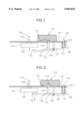
- FIG. 1 is a view showing an operating state that a capstan brake device of a VCR having a capstan brake device according to the present invention is released;
- FIG. 2 is a view showing an operating state of applying the capstan brake device shown in FIG. 1;
- FIG. 3 is an exploded perspective view showing the cam of the VCR having the capstan brake device according to the present invention.
- VCR having a capstan brake device according to the present invention will be described in detail with reference to FIGS. 1, 2 and 3.
- FIG. 1 is a view showing an operating state that a capstan brake device of a VCR having a capstan brake device according to the present invention is released
- FIG. 2 is a view showing an operating state of applying the capstan brake device shown in FIG. 1.
- a brake member 130 swings in the direction designated by an arrow to be shifted from a releasing state to an applying state.
- brake member 130 is shifted from the applying state to the releasing state when swinging in the direction designated by an arrow.
- a chassis 101 is formed with a capstan hole 102 of a predetermined dimension, and a capstan shaft 124 penetrates through capstan hole 102.
- a flywheel 120 incorporated with a great inertia is attached to an end of capstan shaft 124 for constantly maintaining rotating speed of capstan shaft 124.
- a friction plane 122 is formed on the lower surface of flywheel 120 in the circumferential direction.
- Brake member 130 is attached with a pad 132 for enlarging a friction coefficient on an area closely contacting with friction plane 122, and is installed with a hinge 134 for supporting the swing motion of brake member 130 at the central area.
- a fixing rod 133 is connected to brake member 130 by means of hinge 134, and the other end thereof is fixed to the lower plane of chassis 101.
- a support rod 137 is fixed to the other end of brake member 130, and the other end thereof passes through a side hole 105 formed through the center of a cylindrical spring 138 and chassis 101 to constitute a hook 139.
- hook 139 is formed such that a sloped plane is provided in the direction of inserting support rod 137 into side hole 105 to be easily assembled to chassis 101, but inserted support rod 137 is difficult to be separated therefrom due to hook 139.
- Spring 138 is installed between the lower plane of chassis 101 and brake member 130 under the constrained state, and support rod 137 pierces through the central axial line direction of the cylindrically-shaped spring 138.
- One end of operating rod 136 is installed to brake member 130, and the other end thereof passes through a center hole 103 to project over the upper surface of chassis 101 by a predetermined height.
- the portion of being connected with brake member 130 is an area in the midst of an area installed with pad 132 and an area installed with hinge 134.
- a cam 110 fitted with the other end of projecting operating rod 136 is installed to the upper plane of chassis 101.
- a guide groove 112 and an operating groove 114 formed by a deep-set lower plane of cam 110 are formed where cam 110 is in contact with the upper plane of chassis 101.
- FIG. 3 is an exploded perspective view showing the cam of the VCR having the capstan brake device according to the present invention.
- guide groove 112 and operating groove 114 are formed in the plane where cylindrically-shaped cam 110 is in contact with chassis 101.
- cam 110 is installed to be rotatable by being closely attached to the upper plane of chassis 101 by a cam driving apparatus (not shown).
- Guide groove 112 forms a circular arc of a predetermined angle centering about a rotation axial line of cam 110, has a width slightly greater than a diameter of operating rod 136 for being capable of being fitted with operating rod 136 therein, and has a bottom plane 116 formed to be flat while forming a predetermined inclination from the end of one arc side toward the end of another arc side.
- Operating groove 114 is placed to the deep area in the circular arc of guide groove 112.
- the dent is significantly deeper than that of guide groove 112 to clearly define the boundary of operating groove 114 and guide groove 112, and an indenting distance is slightly greater than the diameter of operating rod 136.
- Cam 110 is rotated to place operating rod 136 having been positioned into guide groove 112 into operating groove 114. Then, brake member 130 swings centering about hinge 134 by an elasticity of spring 138 while operating rod 136 ascends. By this operation, pad 132 is closely attached to friction plane 122, and a frictional force is produced to decelerate the rotating speed of flywheel 120 and capstan shaft 124.
- capstan brake device If the capstan brake device is to be shifted from the applying state to the releasing state, the following operation is carried out.
- Cam 110 is rotated counter-clockwise to place operating rod 136 having been positioned into operating groove 114 into guide groove 112. Then, brake member 130 swings backward centering about hinge 134 by overcoming the elasticity of spring 138 while operating rod 136 gradually descends. By this operation, pad 132 is separated from friction plane 122, and flywheel 120 and capstan shaft 124 become freely rotated.
- the VCR having the capstan brake device according to the present invention is effective in that the rotating speed of the flywheel can be constantly decelerated, and the operation of the brake member is promptly and accurately performed.
- a small number of elements are required to lower manufacturing cost and enhance assembly productivity.
Landscapes
- Engineering & Computer Science (AREA)
- General Engineering & Computer Science (AREA)
- Mechanical Engineering (AREA)
- Physics & Mathematics (AREA)
- Electromagnetism (AREA)
- Braking Arrangements (AREA)
- Toys (AREA)
Applications Claiming Priority (2)
| Application Number | Priority Date | Filing Date | Title |
|---|---|---|---|
| KR95-33454 | 1995-09-30 | ||
| KR1019950033454A KR0160229B1 (ko) | 1995-09-30 | 1995-09-30 | 브이.씨.알.용 캠스턴 브레이크 장치 |
Publications (1)
| Publication Number | Publication Date |
|---|---|
| US5845834A true US5845834A (en) | 1998-12-08 |
Family
ID=19428865
Family Applications (1)
| Application Number | Title | Priority Date | Filing Date |
|---|---|---|---|
| US08/719,029 Expired - Fee Related US5845834A (en) | 1995-09-30 | 1996-09-24 | VCR having a capstan brake device |
Country Status (5)
| Country | Link |
|---|---|
| US (1) | US5845834A (2) |
| JP (1) | JP3664823B2 (2) |
| KR (1) | KR0160229B1 (2) |
| CN (1) | CN1099105C (2) |
| IN (1) | IN190926B (2) |
Cited By (2)
| Publication number | Priority date | Publication date | Assignee | Title |
|---|---|---|---|---|
| US20040026184A1 (en) * | 2000-09-22 | 2004-02-12 | Dietmar Baumann | Wheel brake device |
| CN104554330A (zh) * | 2015-01-29 | 2015-04-29 | 山东黄金集团昌邑矿业有限公司 | 一种矿车刹车装置 |
Families Citing this family (2)
| Publication number | Priority date | Publication date | Assignee | Title |
|---|---|---|---|---|
| KR100424562B1 (ko) * | 2000-12-11 | 2004-03-27 | 엘지전자 주식회사 | 자기기록재생기의 캡스턴모터 브레이크장치 |
| CN100425877C (zh) * | 2007-06-13 | 2008-10-15 | 哈尔滨工程大学 | 扭转弹簧驱动铰链的减速机构 |
Citations (8)
| Publication number | Priority date | Publication date | Assignee | Title |
|---|---|---|---|---|
| US3191834A (en) * | 1961-09-27 | 1965-06-29 | Tohoku Oki Electric Company Lt | Tape driving system for tape recorders |
| US3684147A (en) * | 1971-03-08 | 1972-08-15 | Floyd R Ysbrand | Bi-directional drive mechanism with high speed reverse |
| US3708040A (en) * | 1970-08-19 | 1973-01-02 | Kelsey Hayes Co | Disk brake with servo action |
| US4351498A (en) * | 1979-09-19 | 1982-09-28 | Sanyo Electric Co., Ltd. | Cassette tape device |
| US4757885A (en) * | 1981-11-16 | 1988-07-19 | Tecumseh Products Company | Engine control with self-energizing flywheel brake |
| US4951164A (en) * | 1988-02-27 | 1990-08-21 | Sanyo Electric Co., Ltd. | Single motor magnetic recording/playback apparatus using a worm and worm wheel |
| US5472151A (en) * | 1992-11-21 | 1995-12-05 | Goldstar Co., Ltd. | Fast winding device for video cassette tape recorder |
| US5691858A (en) * | 1992-07-08 | 1997-11-25 | Samsung Electronics Co., Ltd. | Magnetic recording and reproducing apparatus having a single master gear and slide member |
Family Cites Families (3)
| Publication number | Priority date | Publication date | Assignee | Title |
|---|---|---|---|---|
| JPS62212951A (ja) * | 1986-03-12 | 1987-09-18 | Hitachi Ltd | 磁気記録再生装置のブレ−キ機構 |
| US4841391A (en) * | 1986-08-27 | 1989-06-20 | Canon Kabushiki Kaisha | Rotary head type recording and/or reproducing apparatus having mode selecting mechanism |
| US4807061A (en) * | 1986-12-31 | 1989-02-21 | Goldstar Co., Ltd. | Rapid reel braking device for a video cassette tape recorder |
-
1995
- 1995-09-30 KR KR1019950033454A patent/KR0160229B1/ko not_active Expired - Fee Related
-
1996
- 1996-09-24 US US08/719,029 patent/US5845834A/en not_active Expired - Fee Related
- 1996-09-26 IN IN1703CA1996 patent/IN190926B/en unknown
- 1996-09-27 JP JP25669096A patent/JP3664823B2/ja not_active Expired - Fee Related
- 1996-09-30 CN CN96122747A patent/CN1099105C/zh not_active Expired - Fee Related
Patent Citations (8)
| Publication number | Priority date | Publication date | Assignee | Title |
|---|---|---|---|---|
| US3191834A (en) * | 1961-09-27 | 1965-06-29 | Tohoku Oki Electric Company Lt | Tape driving system for tape recorders |
| US3708040A (en) * | 1970-08-19 | 1973-01-02 | Kelsey Hayes Co | Disk brake with servo action |
| US3684147A (en) * | 1971-03-08 | 1972-08-15 | Floyd R Ysbrand | Bi-directional drive mechanism with high speed reverse |
| US4351498A (en) * | 1979-09-19 | 1982-09-28 | Sanyo Electric Co., Ltd. | Cassette tape device |
| US4757885A (en) * | 1981-11-16 | 1988-07-19 | Tecumseh Products Company | Engine control with self-energizing flywheel brake |
| US4951164A (en) * | 1988-02-27 | 1990-08-21 | Sanyo Electric Co., Ltd. | Single motor magnetic recording/playback apparatus using a worm and worm wheel |
| US5691858A (en) * | 1992-07-08 | 1997-11-25 | Samsung Electronics Co., Ltd. | Magnetic recording and reproducing apparatus having a single master gear and slide member |
| US5472151A (en) * | 1992-11-21 | 1995-12-05 | Goldstar Co., Ltd. | Fast winding device for video cassette tape recorder |
Cited By (3)
| Publication number | Priority date | Publication date | Assignee | Title |
|---|---|---|---|---|
| US20040026184A1 (en) * | 2000-09-22 | 2004-02-12 | Dietmar Baumann | Wheel brake device |
| US6845853B2 (en) * | 2000-09-22 | 2005-01-25 | Robert Bosch Gmbh | Wheel brake device |
| CN104554330A (zh) * | 2015-01-29 | 2015-04-29 | 山东黄金集团昌邑矿业有限公司 | 一种矿车刹车装置 |
Also Published As
| Publication number | Publication date |
|---|---|
| JPH09115207A (ja) | 1997-05-02 |
| KR0160229B1 (ko) | 1999-01-15 |
| CN1155726A (zh) | 1997-07-30 |
| CN1099105C (zh) | 2003-01-15 |
| KR970017341A (ko) | 1997-04-30 |
| JP3664823B2 (ja) | 2005-06-29 |
| IN190926B (2) | 2003-09-06 |
Similar Documents
| Publication | Publication Date | Title |
|---|---|---|
| US4873595A (en) | Apparatus for positioning a magnetic disk on a disk drive | |
| US5845834A (en) | VCR having a capstan brake device | |
| US4679745A (en) | Reel brake device of a videocassette recorder | |
| US4609164A (en) | Cassette tape machine | |
| JPS6331269Y2 (2) | ||
| US5748406A (en) | Rotational driving apparatus for disks having a magnet disposed on a motor mounting base surface to absorb radial deflections | |
| JPH09106600A (ja) | コンパクトディスクプレーヤーのディスクチャッキング装置 | |
| JPS5914889Y2 (ja) | リニアトラツキングア−ムにおけるア−ムリフタ装置 | |
| JPH05334779A (ja) | ディスクセンタリング機構 | |
| US5417378A (en) | Tape cassette | |
| JPS6331277Y2 (2) | ||
| JP3010842B2 (ja) | テープレコーダのリール台装置 | |
| JPH0712013Y2 (ja) | インクリボン送り装置 | |
| JPS606959Y2 (ja) | カセツト蓋開閉装置 | |
| US5881961A (en) | Reel driving device capable of eliminating friction between a pressing plate and a rotating driving gear | |
| JPH0132202Y2 (2) | ||
| JPH0418093Y2 (2) | ||
| JPH079276Y2 (ja) | テーププレーヤ | |
| JPH084793Y2 (ja) | 埋込型スピーカの取付装置 | |
| JPH02267Y2 (2) | ||
| JPH0319073Y2 (2) | ||
| KR960042648A (ko) | 광디스크 구동용 턴테이블의 중심보정장치 | |
| JPH02113828U (2) | ||
| JPH0394615U (2) | ||
| JPH10334545A (ja) | 磁気テープカセット装置 |
Legal Events
| Date | Code | Title | Description |
|---|---|---|---|
| AS | Assignment |
Owner name: DAEWOO ELECTRONICS CO. LTD., KOREA, REPUBLIC OF Free format text: ASSIGNMENT OF ASSIGNORS INTEREST;ASSIGNOR:AHN, SEONG-ICK;REEL/FRAME:008204/0285 Effective date: 19960921 |
|
| FEPP | Fee payment procedure |
Free format text: PAYOR NUMBER ASSIGNED (ORIGINAL EVENT CODE: ASPN); ENTITY STATUS OF PATENT OWNER: LARGE ENTITY |
|
| FPAY | Fee payment |
Year of fee payment: 4 |
|
| AS | Assignment |
Owner name: DAEWOO ELECTRONICS CORPORATION, KOREA, REPUBLIC OF Free format text: ASSIGNMENT OF ASSIGNORS INTEREST;ASSIGNOR:DAEWOO ELECTRONICS CO., LTD.;REEL/FRAME:013645/0159 Effective date: 20021231 |
|
| FPAY | Fee payment |
Year of fee payment: 8 |
|
| REMI | Maintenance fee reminder mailed | ||
| LAPS | Lapse for failure to pay maintenance fees | ||
| LAPS | Lapse for failure to pay maintenance fees |
Free format text: PATENT EXPIRED FOR FAILURE TO PAY MAINTENANCE FEES (ORIGINAL EVENT CODE: EXP.); ENTITY STATUS OF PATENT OWNER: LARGE ENTITY |
|
| STCH | Information on status: patent discontinuation |
Free format text: PATENT EXPIRED DUE TO NONPAYMENT OF MAINTENANCE FEES UNDER 37 CFR 1.362 |
|
| FP | Lapsed due to failure to pay maintenance fee |
Effective date: 20101208 |