US5839283A - Mixing ducts for a gas-turbine annular combustion chamber - Google Patents
Mixing ducts for a gas-turbine annular combustion chamber Download PDFInfo
- Publication number
- US5839283A US5839283A US08/751,721 US75172196A US5839283A US 5839283 A US5839283 A US 5839283A US 75172196 A US75172196 A US 75172196A US 5839283 A US5839283 A US 5839283A
- Authority
- US
- United States
- Prior art keywords
- combustion chamber
- air
- gas
- turbine
- combustion
- Prior art date
- Legal status (The legal status is an assumption and is not a legal conclusion. Google has not performed a legal analysis and makes no representation as to the accuracy of the status listed.)
- Expired - Fee Related
Links
Images


Classifications
-
- F—MECHANICAL ENGINEERING; LIGHTING; HEATING; WEAPONS; BLASTING
- F23—COMBUSTION APPARATUS; COMBUSTION PROCESSES
- F23R—GENERATING COMBUSTION PRODUCTS OF HIGH PRESSURE OR HIGH VELOCITY, e.g. GAS-TURBINE COMBUSTION CHAMBERS
- F23R3/00—Continuous combustion chambers using liquid or gaseous fuel
- F23R3/02—Continuous combustion chambers using liquid or gaseous fuel characterised by the air-flow or gas-flow configuration
- F23R3/04—Air inlet arrangements
- F23R3/10—Air inlet arrangements for primary air
-
- F—MECHANICAL ENGINEERING; LIGHTING; HEATING; WEAPONS; BLASTING
- F23—COMBUSTION APPARATUS; COMBUSTION PROCESSES
- F23R—GENERATING COMBUSTION PRODUCTS OF HIGH PRESSURE OR HIGH VELOCITY, e.g. GAS-TURBINE COMBUSTION CHAMBERS
- F23R3/00—Continuous combustion chambers using liquid or gaseous fuel
- F23R3/02—Continuous combustion chambers using liquid or gaseous fuel characterised by the air-flow or gas-flow configuration
- F23R3/04—Air inlet arrangements
- F23R3/045—Air inlet arrangements using pipes
-
- F—MECHANICAL ENGINEERING; LIGHTING; HEATING; WEAPONS; BLASTING
- F23—COMBUSTION APPARATUS; COMBUSTION PROCESSES
- F23R—GENERATING COMBUSTION PRODUCTS OF HIGH PRESSURE OR HIGH VELOCITY, e.g. GAS-TURBINE COMBUSTION CHAMBERS
- F23R3/00—Continuous combustion chambers using liquid or gaseous fuel
- F23R3/28—Continuous combustion chambers using liquid or gaseous fuel characterised by the fuel supply
- F23R3/286—Continuous combustion chambers using liquid or gaseous fuel characterised by the fuel supply having fuel-air premixing devices
-
- F—MECHANICAL ENGINEERING; LIGHTING; HEATING; WEAPONS; BLASTING
- F23—COMBUSTION APPARATUS; COMBUSTION PROCESSES
- F23R—GENERATING COMBUSTION PRODUCTS OF HIGH PRESSURE OR HIGH VELOCITY, e.g. GAS-TURBINE COMBUSTION CHAMBERS
- F23R3/00—Continuous combustion chambers using liquid or gaseous fuel
- F23R3/42—Continuous combustion chambers using liquid or gaseous fuel characterised by the arrangement or form of the flame tubes or combustion chambers
- F23R3/50—Combustion chambers comprising an annular flame tube within an annular casing
-
- F—MECHANICAL ENGINEERING; LIGHTING; HEATING; WEAPONS; BLASTING
- F23—COMBUSTION APPARATUS; COMBUSTION PROCESSES
- F23R—GENERATING COMBUSTION PRODUCTS OF HIGH PRESSURE OR HIGH VELOCITY, e.g. GAS-TURBINE COMBUSTION CHAMBERS
- F23R2900/00—Special features of, or arrangements for continuous combustion chambers; Combustion processes therefor
- F23R2900/03041—Effusion cooled combustion chamber walls or domes
Definitions
- the invention relates to the field of combustion technology. More particularly, the invention relates to a gas-turbine annular combustion chamber which is operated with premix burners as well as to a method of operating this device.
- Gas turbines essentially comprise the components compressor, combustion chamber and turbine. For reasons of environmental protection, work is increasingly being carried out with low-pollution premix combustion instead of diffusion combustion.
- the air issuing from the compressor has a very high velocity (about 200 m/s) and, in order to recover the kinetic energy contained in it, is decelerated in a deflection diffuser as far as possible without losses.
- the velocity in the combustion chamber is. greatly reduced again at least locally downstream of the burner.
- a local recirculation zone having negative velocities is usually produced.
- the velocity is then about 50 m/s in order to obtain an adequate residence time and to keep down the heat transfer between hot gas and combustion-chamber wall.
- acceleration is again effected so that velocities of the gas approaching the velocity of sound are achieved at the inlet of the turbine.
- one object of the invention in attempting to avoid all these disadvantages, is to develop a novel gas-turbine annular combustion chamber which is equipped with special premix burners, is distinguished by a small overall size and is simplified compared with the known prior art, improved premixing of fuel and air being effected with a smaller total pressure loss.
- this is achieved in that, in a gas-turbine annular combustion chamber which is arranged downstream of a compressor and is equipped on its front plate with at least one premix-burner row arranged in an annular form, in each case a combustion-air duct designed as a diffuser leads directly downstream of the compressor outlet from the guide vanes of the last compressor row to each burner, at the downstream end of which combustion-air duct at least one longitudinal-vortex generator is located, at least one fuel injection means being provided in or downstream of the longitudinal-vortex generator, and a mixing duct which ends in the combustion chamber and has a constant duct height and a length which corresponds approximately to twice the value of the hydraulic duct height being arranged downstream of the fuel injection means.
- the combustion air directly after discharge from the compressor, is split up into individual air flows for the burners and for the cooling of the combustion chamber and the turbine, the velocity of the air for the burners is then decelerated to approximately half the value of the compressor outlet velocity, and at least one longitudinal vortex is then generated in the air per combustion-air duct, fuel being admixed during or downstream of the longitudinal-vortex generation, the mixture at this point flowing along in a mixing duct and flowing with an overall swirl imposed on it into the combustion chamber and finally being burnt there.
- the advantages of the invention consist, inter alia, in the fact that the combustion chamber has smaller dimensions compared with the prior art and the area to be cooled in the combustion chamber is reduced.
- the pressure loss between compressor outlet and turbine inlet is smaller.
- the air is equally distributed over the burners in a very effective and stable manner and the premixing of fuel and combustion air is improved.
- the ratio of the number of blades of the last compressor row to the number of premix burners is integral, in particular 1 or 2, since a combustion-air duct can then be coupled directly to one or two blade ducts of the last compressor row.
- the mixing duct has an approximately round cross section, since good intermixing of air and fuel is than achieved. But mixing ducts having a rectangular cross section are also conceivable. Likewise, if only one burner row is present, the mixing duct may be designed as a segmented annular gap.
- combustion-air ducts are arranged spirally around the axis of the gas turbine. Axial length can be saved in this way.
- the axes of the mixing ducts i.e. the direction of flow of the mixture entering the combustion chamber
- the mixing and flame stabilization are thereby further improved.
- FIG. 1 shows a partial longitudinal section of a gas-turbine plant having an annular combustion chamber according to the prior art equipped with premix burners
- FIG. 2 shows a partial longitudinal section of a gas-turbine plant having a four-row annular combustion chamber according to the invention
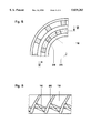
- FIG. 3 shows a partial cross section of a two-row combustion chamber in accordance with a section in the plane III--III of the four-row annular combustion chamber shown in FIG. 2;
- FIG. 4 shows a developed view of the premix section (along IV--IV in FIG. 3) between compressor outlet and combustion-chamber front plate;
- FIG. 5 is a sectioned view of a segmented annular gap for the mixing duct corresponding to the view of FIG. 3;
- FIG. 6 is a sectioned view along the lines VI--VI in FIG. 5.
- FIG. 1 shows first of all a partial longitudinal section of a gas-turbine plant having an annular combustion chamber according to the prior art.
- An annular combustion chamber 4 which is equipped with premix burners 5 of the double-cone type of construction, is arranged between a compressor 1 and a turbine 2, of which only one guide vane 3 of the first guide-vane row is shown.
- the feeding of the fuel 6 to each premix burner 5 is realized via fuel lances 7.
- the annular combustion chamber 4 is cooled convectively or by means of impact cooling.
- the compressor 1 essentially comprises the blade carrier 8, in which the guide vanes 9 are suspended, and the rotor 10, which accommodates the moving blades 11. In FIG. 1, in each case only the last compressor stages are shown.
- a deflection diffuser 12 is arranged at the outlet of the compressor 1. It leads into a plenum 13 arranged between compressor 1 and annular combustion chamber 4.
- the air 14 issuing from the compressor 1 has a very high velocity. It is decelerated in the deflection diffuser 12 in order to recover the kinetic energy contained in it, so that only very low air velocities prevail in the plenum 13 adjoining the deflection diffuser 12. The air 14 can thereby be equally distributed over the burners 5 and cooling air for the combustion chamber 4 and the turbine 2 can be extracted without problem.
- the air 14 has to be greatly accelerated again in the premix zone before a reduction in the velocity is again effected downstream of the burners 5 in the combustion chamber 4 for reasons of flame stability.
- the gas is again accelerated so that velocities close to the velocity of sound are reached at the inlet to the turbine 2.
- the repeated accelerations and decelerations between compressor outlet and turbine inlet involves losses and the requisite repeated deflections of the air mass flow lead to quite a large overall height.
- the outside diameter in the region of the combustion chamber is about 4.5 m.
- FIG. 2 An exemplary embodiment of the invention is shown in FIG. 2 with reference to a four-row gas-turbine annular combustion chamber.
- the air 14 is no longer decelerated to plenum conditions; on the contrary, the deceleration of the air 14 is restricted only to the velocity level of the premix section.
- the repeated deflection of the total air mass flow can thereby be dispensed with and the overall size in the region of the combustion chamber can be substantially reduced.
- a burner air-distributor system is arranged directly downstream of the compressor outlet at the guide vanes 9 of the last compressor-blade row, in which burner air-distributor system in each case a combustion-air duct 15 designed as a diffuser leads to each burner 5 of the annular combustion chamber 4.
- At least one longitudinal-vortex generator 16 is located at the downstream end of the combustion-air duct 15.
- a mixing duct 19 which ends in the combustion chamber 4 and has a constant height H and a length L which corresponds approximately to twice the value of the hydraulic duct diameter D.
- the deflection diffuser 12 and the plenum 13 are therefore dispensed with.
- the air from the compressor 1 is apportioned directly after the discharge from the compressor 1 to a multiplicity of individual ducts, specifically to the combustion-air ducts 15 and to annular ducts 20 arranged on the hub side and casing side respectively for the cooling air 21 of the combustion chamber 4 and the turbine 2, which air is provided here at a high pressure level.
- air 22 can be extracted from the ducts 20 for flushing out the boundary layer forming in the mixing duct 19. This is shown as an example only for the innermost mixing duct 19.
- the combustion-air ducts 15 are configured as diffusers and decelerate the air velocity to about half the value of the compressor outlet velocity, in the course of which a maximum of 75% of the dynamic energy can be converted into a pressure gain.
- one or more longitudinal vortices per combustion-air duct 15 are generated at the longitudinal-vortex generator 16.
- fuel 6 which is fed, for example, through fuel lances 7 is admixed to the air 14 by an integrated fuel injection means 17.
- the fuel injection means 17 may also be arranged downstream of the longitudinal-vortex generators 16 in another exemplary embodiment.
- the generated longitudinal vortices ensure good mixing of fuel 6 and combustion air 14 in the adjoining mixing ducts 19.
- the latter have a constant height H and are approximately twice as long as two hydraulic duct diameters D.
- the mixing ducts 19 have a circular cross section and are thus a mixing tube.
- the mixing-tube axes 24 are arranged parallel to the axis 25 of the gas turbine.
- the mixing ducts 19 may also have a rectangular or polygonal cross a segmented section. As illustrated in FIG. 5 and FIG. 6, the mixing ducts 19 may each be formed as annular gap. A plurality of bars 26 divide the annular duct into segments 19, and vortex generators 16 are mounted in each of the segments.
- FIGS. 1 and 2 are compared, the reduction in the area to be cooled of the combustion-chamber wall according to the invention can clearly be recognized.
- a gas turbine of the 170 MWel class e.g. GT13E2 should serve as an example.
- the outside diameter in the region of the combustion chamber is about 4.5 m according to the prior art (FIG. 1), this value turns out to be only 3.5 m when the invention is used, so that a reduction in the overall size by about 20 is achieved.
- the cooling of the combustion chamber can be effected via film or effusion cooling due to the greatly reduced area to be cooled in the novel combustion chamber and due to the extremely low NOx emissions, obtainable with a good premix-burner technique, at relatively high flame temperatures (theoretically about 5 ppm NOx at 15% O 2 and 1850 K flame temperature).
- FIGS. 3 and 4 show a further exemplary embodiment.
- FIG. 3 shows a partial cross section of a two-row annular combustion chamber in accordance with a section in the plane III--III of the four-row combustion chamber shown in FIG. 2.
- the annular combustion chamber 4 according to FIG. 3 is therefore equipped with two rows of premix burners 5.
- the arrows in FIG. 3 are intended to illustrate an opposed setting angle of the burners 5 in the rows lying side by side. This opposed setting angle ensures that no overall swirl is generated in the combustion chamber 4.
- the cross section of the mixing ducts 19 is not round but elliptical.
- combustion-air ducts 15 are arranged spirally around the axis 25 of the gas turbine in order to keep the axial length of the machine as small as possible.
Landscapes
- Engineering & Computer Science (AREA)
- Chemical & Material Sciences (AREA)
- Combustion & Propulsion (AREA)
- Mechanical Engineering (AREA)
- General Engineering & Computer Science (AREA)
- Turbine Rotor Nozzle Sealing (AREA)
Applications Claiming Priority (2)
| Application Number | Priority Date | Filing Date | Title |
|---|---|---|---|
| DE19549143.2 | 1995-12-29 | ||
| DE19549143A DE19549143A1 (de) | 1995-12-29 | 1995-12-29 | Gasturbinenringbrennkammer |
Publications (1)
| Publication Number | Publication Date |
|---|---|
| US5839283A true US5839283A (en) | 1998-11-24 |
Family
ID=7781645
Family Applications (1)
| Application Number | Title | Priority Date | Filing Date |
|---|---|---|---|
| US08/751,721 Expired - Fee Related US5839283A (en) | 1995-12-29 | 1996-11-18 | Mixing ducts for a gas-turbine annular combustion chamber |
Country Status (5)
| Country | Link |
|---|---|
| US (1) | US5839283A (zh) |
| EP (1) | EP0781967B1 (zh) |
| JP (1) | JPH09196379A (zh) |
| CN (1) | CN1088151C (zh) |
| DE (2) | DE19549143A1 (zh) |
Cited By (125)
| Publication number | Priority date | Publication date | Assignee | Title |
|---|---|---|---|---|
| US6405703B1 (en) | 2001-06-29 | 2002-06-18 | Brian Sowards | Internal combustion engine |
| EP1288576A2 (en) * | 2001-08-24 | 2003-03-05 | Mitsubishi Heavy Industries, Ltd. | Gas turbine combustor |
| US6564555B2 (en) | 2001-05-24 | 2003-05-20 | Allison Advanced Development Company | Apparatus for forming a combustion mixture in a gas turbine engine |
| US20040011041A1 (en) * | 2001-08-28 | 2004-01-22 | Honda Giken Kogyo Kabushiki Kaisha | Gas-turbine engine combustor |
| US20040011042A1 (en) * | 2001-08-28 | 2004-01-22 | Honda Giken Kogyo Kabushiki Kaisha | Gas-turbine engine combustor |
| US20040020211A1 (en) * | 2001-07-23 | 2004-02-05 | Ramgen Power Systems, Inc. | Trapped vortex combustor |
| US6694743B2 (en) | 2001-07-23 | 2004-02-24 | Ramgen Power Systems, Inc. | Rotary ramjet engine with flameholder extending to running clearance at engine casing interior wall |
| EP1507120A1 (de) * | 2003-08-13 | 2005-02-16 | Siemens Aktiengesellschaft | Gasturbine |
| US20060156734A1 (en) * | 2005-01-15 | 2006-07-20 | Siemens Westinghouse Power Corporation | Gas turbine combustor |
| WO2007102807A1 (en) * | 2006-03-06 | 2007-09-13 | United Technologies Corporation | Angled flow annular combustor for turbine engine |
| US20090113895A1 (en) * | 2001-07-23 | 2009-05-07 | Steele Robert C | Vortex combustor for low NOx emissions when burning lean premixed high hydrogen content fuel |
| US20090241547A1 (en) * | 2008-03-31 | 2009-10-01 | Andrew Luts | Gas turbine fuel injector for lower heating capacity fuels |
| US20100158683A1 (en) * | 2008-12-22 | 2010-06-24 | Macfarlane Ian | Exhaust gas discharge system and plenum |
| US20100239418A1 (en) * | 2009-03-19 | 2010-09-23 | General Electric Company | Compressor diffuser |
| US20110016878A1 (en) * | 2009-07-24 | 2011-01-27 | General Electric Company | Systems and Methods for Gas Turbine Combustors |
| US20110179803A1 (en) * | 2010-01-27 | 2011-07-28 | General Electric Company | Bled diffuser fed secondary combustion system for gas turbines |
| US20130086914A1 (en) * | 2011-10-05 | 2013-04-11 | General Electric Company | Turbine system |
| EP2587021A1 (en) | 2011-10-24 | 2013-05-01 | Siemens Aktiengesellschaft | Gas turbine and method for guiding compressed fluid in a gas turbine |
| US8448450B2 (en) | 2011-07-05 | 2013-05-28 | General Electric Company | Support assembly for transition duct in turbine system |
| US8459041B2 (en) | 2011-11-09 | 2013-06-11 | General Electric Company | Leaf seal for transition duct in turbine system |
| US8650852B2 (en) | 2011-07-05 | 2014-02-18 | General Electric Company | Support assembly for transition duct in turbine system |
| US8701415B2 (en) | 2011-11-09 | 2014-04-22 | General Electric Company | Flexible metallic seal for transition duct in turbine system |
| US8707673B1 (en) | 2013-01-04 | 2014-04-29 | General Electric Company | Articulated transition duct in turbomachine |
| US8734545B2 (en) | 2008-03-28 | 2014-05-27 | Exxonmobil Upstream Research Company | Low emission power generation and hydrocarbon recovery systems and methods |
| US8974179B2 (en) | 2011-11-09 | 2015-03-10 | General Electric Company | Convolution seal for transition duct in turbine system |
| US8978388B2 (en) | 2011-06-03 | 2015-03-17 | General Electric Company | Load member for transition duct in turbine system |
| US8984857B2 (en) | 2008-03-28 | 2015-03-24 | Exxonmobil Upstream Research Company | Low emission power generation and hydrocarbon recovery systems and methods |
| US9027321B2 (en) | 2008-03-28 | 2015-05-12 | Exxonmobil Upstream Research Company | Low emission power generation and hydrocarbon recovery systems and methods |
| US9038394B2 (en) | 2012-04-30 | 2015-05-26 | General Electric Company | Convolution seal for transition duct in turbine system |
| US9080447B2 (en) | 2013-03-21 | 2015-07-14 | General Electric Company | Transition duct with divided upstream and downstream portions |
| EP2899368A1 (en) * | 2014-01-23 | 2015-07-29 | Honeywell International Inc. | Gas turbine engine assembly with diffuser vane count and fuel injection assembly count relationships |
| US9133722B2 (en) | 2012-04-30 | 2015-09-15 | General Electric Company | Transition duct with late injection in turbine system |
| US9140452B2 (en) | 2009-10-28 | 2015-09-22 | Man Diesel & Turbo Se | Combustor head plate assembly with impingement |
| US9151223B2 (en) | 2010-06-15 | 2015-10-06 | Rolls-Royce Deutschland Ltd & Co Kg | Gas turbine combustion chamber arrangement of axial type of construction |
| US9151501B2 (en) | 2011-07-28 | 2015-10-06 | Rolls-Royce Deutschland Ltd & Co Kg | Gas turbine centripetal annular combustion chamber and method for flow guidance |
| US9222671B2 (en) | 2008-10-14 | 2015-12-29 | Exxonmobil Upstream Research Company | Methods and systems for controlling the products of combustion |
| US20160018110A1 (en) * | 2014-07-18 | 2016-01-21 | Peter John Stuttaford | Axially staged gas turbine combustor with interstage premixer |
| US9353682B2 (en) | 2012-04-12 | 2016-05-31 | General Electric Company | Methods, systems and apparatus relating to combustion turbine power plants with exhaust gas recirculation |
| US9458732B2 (en) | 2013-10-25 | 2016-10-04 | General Electric Company | Transition duct assembly with modified trailing edge in turbine system |
| US9463417B2 (en) | 2011-03-22 | 2016-10-11 | Exxonmobil Upstream Research Company | Low emission power generation systems and methods incorporating carbon dioxide separation |
| US9512759B2 (en) | 2013-02-06 | 2016-12-06 | General Electric Company | System and method for catalyst heat utilization for gas turbine with exhaust gas recirculation |
| US9574496B2 (en) | 2012-12-28 | 2017-02-21 | General Electric Company | System and method for a turbine combustor |
| US9581081B2 (en) | 2013-01-13 | 2017-02-28 | General Electric Company | System and method for protecting components in a gas turbine engine with exhaust gas recirculation |
| US9587510B2 (en) | 2013-07-30 | 2017-03-07 | General Electric Company | System and method for a gas turbine engine sensor |
| US9599021B2 (en) | 2011-03-22 | 2017-03-21 | Exxonmobil Upstream Research Company | Systems and methods for controlling stoichiometric combustion in low emission turbine systems |
| US9599070B2 (en) | 2012-11-02 | 2017-03-21 | General Electric Company | System and method for oxidant compression in a stoichiometric exhaust gas recirculation gas turbine system |
| US9611756B2 (en) | 2012-11-02 | 2017-04-04 | General Electric Company | System and method for protecting components in a gas turbine engine with exhaust gas recirculation |
| US9618261B2 (en) | 2013-03-08 | 2017-04-11 | Exxonmobil Upstream Research Company | Power generation and LNG production |
| US9617914B2 (en) | 2013-06-28 | 2017-04-11 | General Electric Company | Systems and methods for monitoring gas turbine systems having exhaust gas recirculation |
| US9631815B2 (en) | 2012-12-28 | 2017-04-25 | General Electric Company | System and method for a turbine combustor |
| US9631542B2 (en) | 2013-06-28 | 2017-04-25 | General Electric Company | System and method for exhausting combustion gases from gas turbine engines |
| US9670841B2 (en) | 2011-03-22 | 2017-06-06 | Exxonmobil Upstream Research Company | Methods of varying low emission turbine gas recycle circuits and systems and apparatus related thereto |
| US9689309B2 (en) | 2011-03-22 | 2017-06-27 | Exxonmobil Upstream Research Company | Systems and methods for carbon dioxide capture in low emission combined turbine systems |
| US9708977B2 (en) | 2012-12-28 | 2017-07-18 | General Electric Company | System and method for reheat in gas turbine with exhaust gas recirculation |
| US9732675B2 (en) | 2010-07-02 | 2017-08-15 | Exxonmobil Upstream Research Company | Low emission power generation systems and methods |
| US9732673B2 (en) | 2010-07-02 | 2017-08-15 | Exxonmobil Upstream Research Company | Stoichiometric combustion with exhaust gas recirculation and direct contact cooler |
| US9752458B2 (en) | 2013-12-04 | 2017-09-05 | General Electric Company | System and method for a gas turbine engine |
| US9784185B2 (en) | 2012-04-26 | 2017-10-10 | General Electric Company | System and method for cooling a gas turbine with an exhaust gas provided by the gas turbine |
| US9784140B2 (en) | 2013-03-08 | 2017-10-10 | Exxonmobil Upstream Research Company | Processing exhaust for use in enhanced oil recovery |
| US9784182B2 (en) | 2013-03-08 | 2017-10-10 | Exxonmobil Upstream Research Company | Power generation and methane recovery from methane hydrates |
| US9803865B2 (en) | 2012-12-28 | 2017-10-31 | General Electric Company | System and method for a turbine combustor |
| US9810050B2 (en) | 2011-12-20 | 2017-11-07 | Exxonmobil Upstream Research Company | Enhanced coal-bed methane production |
| US9819292B2 (en) | 2014-12-31 | 2017-11-14 | General Electric Company | Systems and methods to respond to grid overfrequency events for a stoichiometric exhaust recirculation gas turbine |
| US9835089B2 (en) | 2013-06-28 | 2017-12-05 | General Electric Company | System and method for a fuel nozzle |
| US9863267B2 (en) | 2014-01-21 | 2018-01-09 | General Electric Company | System and method of control for a gas turbine engine |
| US9869279B2 (en) | 2012-11-02 | 2018-01-16 | General Electric Company | System and method for a multi-wall turbine combustor |
| US9869247B2 (en) | 2014-12-31 | 2018-01-16 | General Electric Company | Systems and methods of estimating a combustion equivalence ratio in a gas turbine with exhaust gas recirculation |
| US9885290B2 (en) | 2014-06-30 | 2018-02-06 | General Electric Company | Erosion suppression system and method in an exhaust gas recirculation gas turbine system |
| US9903316B2 (en) | 2010-07-02 | 2018-02-27 | Exxonmobil Upstream Research Company | Stoichiometric combustion of enriched air with exhaust gas recirculation |
| US9903588B2 (en) | 2013-07-30 | 2018-02-27 | General Electric Company | System and method for barrier in passage of combustor of gas turbine engine with exhaust gas recirculation |
| US9903271B2 (en) | 2010-07-02 | 2018-02-27 | Exxonmobil Upstream Research Company | Low emission triple-cycle power generation and CO2 separation systems and methods |
| US9915200B2 (en) | 2014-01-21 | 2018-03-13 | General Electric Company | System and method for controlling the combustion process in a gas turbine operating with exhaust gas recirculation |
| US9932874B2 (en) | 2013-02-21 | 2018-04-03 | Exxonmobil Upstream Research Company | Reducing oxygen in a gas turbine exhaust |
| US9938861B2 (en) | 2013-02-21 | 2018-04-10 | Exxonmobil Upstream Research Company | Fuel combusting method |
| US9951658B2 (en) | 2013-07-31 | 2018-04-24 | General Electric Company | System and method for an oxidant heating system |
| US9951956B2 (en) | 2015-12-28 | 2018-04-24 | General Electric Company | Fuel nozzle assembly having a premix fuel stabilizer |
| US10012151B2 (en) | 2013-06-28 | 2018-07-03 | General Electric Company | Systems and methods for controlling exhaust gas flow in exhaust gas recirculation gas turbine systems |
| US10030588B2 (en) | 2013-12-04 | 2018-07-24 | General Electric Company | Gas turbine combustor diagnostic system and method |
| US10047633B2 (en) | 2014-05-16 | 2018-08-14 | General Electric Company | Bearing housing |
| US10060359B2 (en) | 2014-06-30 | 2018-08-28 | General Electric Company | Method and system for combustion control for gas turbine system with exhaust gas recirculation |
| US10079564B2 (en) | 2014-01-27 | 2018-09-18 | General Electric Company | System and method for a stoichiometric exhaust gas recirculation gas turbine system |
| US10094566B2 (en) | 2015-02-04 | 2018-10-09 | General Electric Company | Systems and methods for high volumetric oxidant flow in gas turbine engine with exhaust gas recirculation |
| US10100741B2 (en) | 2012-11-02 | 2018-10-16 | General Electric Company | System and method for diffusion combustion with oxidant-diluent mixing in a stoichiometric exhaust gas recirculation gas turbine system |
| US10107495B2 (en) | 2012-11-02 | 2018-10-23 | General Electric Company | Gas turbine combustor control system for stoichiometric combustion in the presence of a diluent |
| US10145251B2 (en) | 2016-03-24 | 2018-12-04 | General Electric Company | Transition duct assembly |
| US10145269B2 (en) | 2015-03-04 | 2018-12-04 | General Electric Company | System and method for cooling discharge flow |
| US10208677B2 (en) | 2012-12-31 | 2019-02-19 | General Electric Company | Gas turbine load control system |
| US10215412B2 (en) | 2012-11-02 | 2019-02-26 | General Electric Company | System and method for load control with diffusion combustion in a stoichiometric exhaust gas recirculation gas turbine system |
| US10221762B2 (en) | 2013-02-28 | 2019-03-05 | General Electric Company | System and method for a turbine combustor |
| US10227883B2 (en) | 2016-03-24 | 2019-03-12 | General Electric Company | Transition duct assembly |
| US10227920B2 (en) | 2014-01-15 | 2019-03-12 | General Electric Company | Gas turbine oxidant separation system |
| US10253690B2 (en) | 2015-02-04 | 2019-04-09 | General Electric Company | Turbine system with exhaust gas recirculation, separation and extraction |
| US10260752B2 (en) | 2016-03-24 | 2019-04-16 | General Electric Company | Transition duct assembly with late injection features |
| US10260424B2 (en) | 2016-03-24 | 2019-04-16 | General Electric Company | Transition duct assembly with late injection features |
| US10260360B2 (en) | 2016-03-24 | 2019-04-16 | General Electric Company | Transition duct assembly |
| US10267270B2 (en) | 2015-02-06 | 2019-04-23 | General Electric Company | Systems and methods for carbon black production with a gas turbine engine having exhaust gas recirculation |
| US10267522B2 (en) * | 2012-10-23 | 2019-04-23 | Ansaldo Energia Switzerland AG | Burner for a combustion chamber of a gas turbine having a mixing and injection device |
| US10273880B2 (en) | 2012-04-26 | 2019-04-30 | General Electric Company | System and method of recirculating exhaust gas for use in a plurality of flow paths in a gas turbine engine |
| US10295190B2 (en) | 2016-11-04 | 2019-05-21 | General Electric Company | Centerbody injector mini mixer fuel nozzle assembly |
| US10315150B2 (en) | 2013-03-08 | 2019-06-11 | Exxonmobil Upstream Research Company | Carbon dioxide recovery |
| US10316746B2 (en) | 2015-02-04 | 2019-06-11 | General Electric Company | Turbine system with exhaust gas recirculation, separation and extraction |
| US10352569B2 (en) | 2016-11-04 | 2019-07-16 | General Electric Company | Multi-point centerbody injector mini mixing fuel nozzle assembly |
| US10393382B2 (en) | 2016-11-04 | 2019-08-27 | General Electric Company | Multi-point injection mini mixing fuel nozzle assembly |
| US10465909B2 (en) | 2016-11-04 | 2019-11-05 | General Electric Company | Mini mixing fuel nozzle assembly with mixing sleeve |
| US10480792B2 (en) | 2015-03-06 | 2019-11-19 | General Electric Company | Fuel staging in a gas turbine engine |
| US10584876B2 (en) * | 2016-03-25 | 2020-03-10 | General Electric Company | Micro-channel cooling of integrated combustor nozzle of a segmented annular combustion system |
| US10584880B2 (en) * | 2016-03-25 | 2020-03-10 | General Electric Company | Mounting of integrated combustor nozzles in a segmented annular combustion system |
| US10605459B2 (en) * | 2016-03-25 | 2020-03-31 | General Electric Company | Integrated combustor nozzle for a segmented annular combustion system |
| US10634353B2 (en) | 2017-01-12 | 2020-04-28 | General Electric Company | Fuel nozzle assembly with micro channel cooling |
| US10655542B2 (en) | 2014-06-30 | 2020-05-19 | General Electric Company | Method and system for startup of gas turbine system drive trains with exhaust gas recirculation |
| US10724740B2 (en) | 2016-11-04 | 2020-07-28 | General Electric Company | Fuel nozzle assembly with impingement purge |
| US10788212B2 (en) | 2015-01-12 | 2020-09-29 | General Electric Company | System and method for an oxidant passageway in a gas turbine system with exhaust gas recirculation |
| US10890329B2 (en) | 2018-03-01 | 2021-01-12 | General Electric Company | Fuel injector assembly for gas turbine engine |
| US10935245B2 (en) | 2018-11-20 | 2021-03-02 | General Electric Company | Annular concentric fuel nozzle assembly with annular depression and radial inlet ports |
| US11073114B2 (en) | 2018-12-12 | 2021-07-27 | General Electric Company | Fuel injector assembly for a heat engine |
| US11156360B2 (en) | 2019-02-18 | 2021-10-26 | General Electric Company | Fuel nozzle assembly |
| US11255545B1 (en) | 2020-10-26 | 2022-02-22 | General Electric Company | Integrated combustion nozzle having a unified head end |
| US11286884B2 (en) | 2018-12-12 | 2022-03-29 | General Electric Company | Combustion section and fuel injector assembly for a heat engine |
| US11371702B2 (en) | 2020-08-31 | 2022-06-28 | General Electric Company | Impingement panel for a turbomachine |
| US11460191B2 (en) | 2020-08-31 | 2022-10-04 | General Electric Company | Cooling insert for a turbomachine |
| US11614233B2 (en) | 2020-08-31 | 2023-03-28 | General Electric Company | Impingement panel support structure and method of manufacture |
| US11732892B2 (en) | 2013-08-14 | 2023-08-22 | General Electric Company | Gas turbomachine diffuser assembly with radial flow splitters |
| US11767766B1 (en) | 2022-07-29 | 2023-09-26 | General Electric Company | Turbomachine airfoil having impingement cooling passages |
| US20240068402A1 (en) * | 2022-08-25 | 2024-02-29 | Collins Engine Nozzles, Inc. | Fuel injectors assemblies with tangential flow component |
| US11994292B2 (en) | 2020-08-31 | 2024-05-28 | General Electric Company | Impingement cooling apparatus for turbomachine |
Families Citing this family (11)
| Publication number | Priority date | Publication date | Assignee | Title |
|---|---|---|---|---|
| US6119459A (en) * | 1998-08-18 | 2000-09-19 | Alliedsignal Inc. | Elliptical axial combustor swirler |
| DE19914666B4 (de) * | 1999-03-31 | 2009-08-20 | Alstom | Brenner für einen Wärmeerzeuger |
| IL165233A (en) * | 2004-11-16 | 2013-06-27 | Israel Hirshberg | Energy conversion facility |
| DE102006004840A1 (de) * | 2006-02-02 | 2007-08-23 | Rolls-Royce Deutschland Ltd & Co Kg | Gasturbinenbrennkammer mit Kraftstoffeinspritzung über den gesamten Brennkammerring |
| FR2917487B1 (fr) * | 2007-06-14 | 2009-10-02 | Snecma Sa | Chambre de combustion de turbomachine a circulation helicoidale de l'air |
| EP2397764A1 (de) * | 2010-06-18 | 2011-12-21 | Siemens Aktiengesellschaft | Turbinenbrenner |
| FR2982010B1 (fr) * | 2011-10-26 | 2013-11-08 | Snecma | Chambre de combustion annulaire dans une turbomachine |
| US10465907B2 (en) * | 2015-09-09 | 2019-11-05 | General Electric Company | System and method having annular flow path architecture |
| CN111396926B (zh) * | 2020-04-02 | 2021-12-07 | 西北工业大学 | 一种放气式扩压器与火焰筒一体式的燃烧室 |
| KR102663869B1 (ko) | 2022-01-18 | 2024-05-03 | 두산에너빌리티 주식회사 | 연소기용 노즐, 연소기 및 이를 포함하는 가스 터빈 |
| CN114576655A (zh) * | 2022-03-09 | 2022-06-03 | 西北工业大学 | 一种扰流柱带风扇的燃烧室火焰筒壁层板冷却结构 |
Citations (11)
| Publication number | Priority date | Publication date | Assignee | Title |
|---|---|---|---|---|
| US2627721A (en) * | 1947-01-30 | 1953-02-10 | Packard Motor Car Co | Combustion means for jet propulsion units |
| US3299632A (en) * | 1964-05-08 | 1967-01-24 | Rolls Royce | Combustion chamber for a gas turbine engine |
| US4455840A (en) * | 1981-03-04 | 1984-06-26 | Bbc Brown, Boveri & Company, Limited | Ring combustion chamber with ring burner for gas turbines |
| US4991398A (en) * | 1989-01-12 | 1991-02-12 | United Technologies Corporation | Combustor fuel nozzle arrangement |
| US5207064A (en) * | 1990-11-21 | 1993-05-04 | General Electric Company | Staged, mixed combustor assembly having low emissions |
| US5400587A (en) * | 1991-11-13 | 1995-03-28 | Asea Brown Boveri Ltd. | Gas turbine annular combustion chamber having radially displaced groups of oppositely swirling burners. |
| US5557918A (en) * | 1994-06-03 | 1996-09-24 | Abb Research Ltd. | Gas turbine and method of operating it |
| US5573395A (en) * | 1994-04-02 | 1996-11-12 | Abb Management Ag | Premixing burner |
| US5588826A (en) * | 1994-10-01 | 1996-12-31 | Abb Management Ag | Burner |
| US5592820A (en) * | 1993-10-27 | 1997-01-14 | Societe National D'etdue Et De Construction De Moteurs D'aviation S.N.E.C.M.A | Gas turbine diffuser |
| US5619855A (en) * | 1995-06-07 | 1997-04-15 | General Electric Company | High inlet mach combustor for gas turbine engine |
Family Cites Families (3)
| Publication number | Priority date | Publication date | Assignee | Title |
|---|---|---|---|---|
| US3879939A (en) * | 1973-04-18 | 1975-04-29 | United Aircraft Corp | Combustion inlet diffuser employing boundary layer flow straightening vanes |
| GB1581050A (en) * | 1976-12-23 | 1980-12-10 | Rolls Royce | Combustion equipment for gas turbine engines |
| DE3836446A1 (de) * | 1988-10-26 | 1990-05-03 | Proizv Ob Nevskij Z Im V I | Verfahren fuer die luftzufuhr zur brennzone einer brennkammer und brennkammer zur durchfuehrung dieses verfahrens |
-
1995
- 1995-12-29 DE DE19549143A patent/DE19549143A1/de not_active Withdrawn
-
1996
- 1996-11-12 DE DE59610298T patent/DE59610298D1/de not_active Expired - Fee Related
- 1996-11-12 EP EP96810777A patent/EP0781967B1/de not_active Expired - Lifetime
- 1996-11-18 US US08/751,721 patent/US5839283A/en not_active Expired - Fee Related
- 1996-12-25 JP JP8345880A patent/JPH09196379A/ja not_active Abandoned
- 1996-12-27 CN CN96123618A patent/CN1088151C/zh not_active Expired - Fee Related
Patent Citations (11)
| Publication number | Priority date | Publication date | Assignee | Title |
|---|---|---|---|---|
| US2627721A (en) * | 1947-01-30 | 1953-02-10 | Packard Motor Car Co | Combustion means for jet propulsion units |
| US3299632A (en) * | 1964-05-08 | 1967-01-24 | Rolls Royce | Combustion chamber for a gas turbine engine |
| US4455840A (en) * | 1981-03-04 | 1984-06-26 | Bbc Brown, Boveri & Company, Limited | Ring combustion chamber with ring burner for gas turbines |
| US4991398A (en) * | 1989-01-12 | 1991-02-12 | United Technologies Corporation | Combustor fuel nozzle arrangement |
| US5207064A (en) * | 1990-11-21 | 1993-05-04 | General Electric Company | Staged, mixed combustor assembly having low emissions |
| US5400587A (en) * | 1991-11-13 | 1995-03-28 | Asea Brown Boveri Ltd. | Gas turbine annular combustion chamber having radially displaced groups of oppositely swirling burners. |
| US5592820A (en) * | 1993-10-27 | 1997-01-14 | Societe National D'etdue Et De Construction De Moteurs D'aviation S.N.E.C.M.A | Gas turbine diffuser |
| US5573395A (en) * | 1994-04-02 | 1996-11-12 | Abb Management Ag | Premixing burner |
| US5557918A (en) * | 1994-06-03 | 1996-09-24 | Abb Research Ltd. | Gas turbine and method of operating it |
| US5588826A (en) * | 1994-10-01 | 1996-12-31 | Abb Management Ag | Burner |
| US5619855A (en) * | 1995-06-07 | 1997-04-15 | General Electric Company | High inlet mach combustor for gas turbine engine |
Cited By (158)
| Publication number | Priority date | Publication date | Assignee | Title |
|---|---|---|---|---|
| US6564555B2 (en) | 2001-05-24 | 2003-05-20 | Allison Advanced Development Company | Apparatus for forming a combustion mixture in a gas turbine engine |
| US6405703B1 (en) | 2001-06-29 | 2002-06-18 | Brian Sowards | Internal combustion engine |
| US8312725B2 (en) | 2001-07-23 | 2012-11-20 | Ramgen Power Systems, Llc | Vortex combustor for low NOX emissions when burning lean premixed high hydrogen content fuel |
| US7003961B2 (en) | 2001-07-23 | 2006-02-28 | Ramgen Power Systems, Inc. | Trapped vortex combustor |
| US20100170263A1 (en) * | 2001-07-23 | 2010-07-08 | Ramgen Power Systems, Llc | Vortex Combustor for Low NOX Emissions when Burning Lean Premixed High Hydrogen Content Fuel |
| US20040020211A1 (en) * | 2001-07-23 | 2004-02-05 | Ramgen Power Systems, Inc. | Trapped vortex combustor |
| US6694743B2 (en) | 2001-07-23 | 2004-02-24 | Ramgen Power Systems, Inc. | Rotary ramjet engine with flameholder extending to running clearance at engine casing interior wall |
| US7603841B2 (en) | 2001-07-23 | 2009-10-20 | Ramgen Power Systems, Llc | Vortex combustor for low NOx emissions when burning lean premixed high hydrogen content fuel |
| US20090113895A1 (en) * | 2001-07-23 | 2009-05-07 | Steele Robert C | Vortex combustor for low NOx emissions when burning lean premixed high hydrogen content fuel |
| EP1288576A2 (en) * | 2001-08-24 | 2003-03-05 | Mitsubishi Heavy Industries, Ltd. | Gas turbine combustor |
| EP1288576A3 (en) * | 2001-08-24 | 2004-01-07 | Mitsubishi Heavy Industries, Ltd. | Gas turbine combustor |
| US6722133B2 (en) * | 2001-08-28 | 2004-04-20 | Honda Giken Kogyo Kabushiki Kaisha | Gas-turbine engine combustor |
| US20040011042A1 (en) * | 2001-08-28 | 2004-01-22 | Honda Giken Kogyo Kabushiki Kaisha | Gas-turbine engine combustor |
| US20040011041A1 (en) * | 2001-08-28 | 2004-01-22 | Honda Giken Kogyo Kabushiki Kaisha | Gas-turbine engine combustor |
| US6718769B2 (en) * | 2001-08-28 | 2004-04-13 | Honda Giken Kogyo Kabushiki Kaisha | Gas-turbine engine combustor having venturi mixers for premixed and diffusive combustion |
| EP1507120A1 (de) * | 2003-08-13 | 2005-02-16 | Siemens Aktiengesellschaft | Gasturbine |
| US20060156734A1 (en) * | 2005-01-15 | 2006-07-20 | Siemens Westinghouse Power Corporation | Gas turbine combustor |
| WO2007102807A1 (en) * | 2006-03-06 | 2007-09-13 | United Technologies Corporation | Angled flow annular combustor for turbine engine |
| US9027321B2 (en) | 2008-03-28 | 2015-05-12 | Exxonmobil Upstream Research Company | Low emission power generation and hydrocarbon recovery systems and methods |
| US8984857B2 (en) | 2008-03-28 | 2015-03-24 | Exxonmobil Upstream Research Company | Low emission power generation and hydrocarbon recovery systems and methods |
| US8734545B2 (en) | 2008-03-28 | 2014-05-27 | Exxonmobil Upstream Research Company | Low emission power generation and hydrocarbon recovery systems and methods |
| US20090241547A1 (en) * | 2008-03-31 | 2009-10-01 | Andrew Luts | Gas turbine fuel injector for lower heating capacity fuels |
| US9719682B2 (en) | 2008-10-14 | 2017-08-01 | Exxonmobil Upstream Research Company | Methods and systems for controlling the products of combustion |
| US10495306B2 (en) | 2008-10-14 | 2019-12-03 | Exxonmobil Upstream Research Company | Methods and systems for controlling the products of combustion |
| US9222671B2 (en) | 2008-10-14 | 2015-12-29 | Exxonmobil Upstream Research Company | Methods and systems for controlling the products of combustion |
| US20100158683A1 (en) * | 2008-12-22 | 2010-06-24 | Macfarlane Ian | Exhaust gas discharge system and plenum |
| US8221073B2 (en) | 2008-12-22 | 2012-07-17 | Pratt & Whitney Canada Corp. | Exhaust gas discharge system and plenum |
| US8133017B2 (en) | 2009-03-19 | 2012-03-13 | General Electric Company | Compressor diffuser |
| US20100239418A1 (en) * | 2009-03-19 | 2010-09-23 | General Electric Company | Compressor diffuser |
| US8474266B2 (en) | 2009-07-24 | 2013-07-02 | General Electric Company | System and method for a gas turbine combustor having a bleed duct from a diffuser to a fuel nozzle |
| US8893511B2 (en) | 2009-07-24 | 2014-11-25 | General Electric Company | Systems and methods for a gas turbine combustor having a bleed duct |
| US20110016878A1 (en) * | 2009-07-24 | 2011-01-27 | General Electric Company | Systems and Methods for Gas Turbine Combustors |
| US9140452B2 (en) | 2009-10-28 | 2015-09-22 | Man Diesel & Turbo Se | Combustor head plate assembly with impingement |
| US8381532B2 (en) | 2010-01-27 | 2013-02-26 | General Electric Company | Bled diffuser fed secondary combustion system for gas turbines |
| US20110179803A1 (en) * | 2010-01-27 | 2011-07-28 | General Electric Company | Bled diffuser fed secondary combustion system for gas turbines |
| US9151223B2 (en) | 2010-06-15 | 2015-10-06 | Rolls-Royce Deutschland Ltd & Co Kg | Gas turbine combustion chamber arrangement of axial type of construction |
| US9732675B2 (en) | 2010-07-02 | 2017-08-15 | Exxonmobil Upstream Research Company | Low emission power generation systems and methods |
| US9732673B2 (en) | 2010-07-02 | 2017-08-15 | Exxonmobil Upstream Research Company | Stoichiometric combustion with exhaust gas recirculation and direct contact cooler |
| US9903316B2 (en) | 2010-07-02 | 2018-02-27 | Exxonmobil Upstream Research Company | Stoichiometric combustion of enriched air with exhaust gas recirculation |
| US9903271B2 (en) | 2010-07-02 | 2018-02-27 | Exxonmobil Upstream Research Company | Low emission triple-cycle power generation and CO2 separation systems and methods |
| US9670841B2 (en) | 2011-03-22 | 2017-06-06 | Exxonmobil Upstream Research Company | Methods of varying low emission turbine gas recycle circuits and systems and apparatus related thereto |
| US9463417B2 (en) | 2011-03-22 | 2016-10-11 | Exxonmobil Upstream Research Company | Low emission power generation systems and methods incorporating carbon dioxide separation |
| US9599021B2 (en) | 2011-03-22 | 2017-03-21 | Exxonmobil Upstream Research Company | Systems and methods for controlling stoichiometric combustion in low emission turbine systems |
| US9689309B2 (en) | 2011-03-22 | 2017-06-27 | Exxonmobil Upstream Research Company | Systems and methods for carbon dioxide capture in low emission combined turbine systems |
| US8978388B2 (en) | 2011-06-03 | 2015-03-17 | General Electric Company | Load member for transition duct in turbine system |
| US8650852B2 (en) | 2011-07-05 | 2014-02-18 | General Electric Company | Support assembly for transition duct in turbine system |
| US8448450B2 (en) | 2011-07-05 | 2013-05-28 | General Electric Company | Support assembly for transition duct in turbine system |
| US9151501B2 (en) | 2011-07-28 | 2015-10-06 | Rolls-Royce Deutschland Ltd & Co Kg | Gas turbine centripetal annular combustion chamber and method for flow guidance |
| US9328623B2 (en) * | 2011-10-05 | 2016-05-03 | General Electric Company | Turbine system |
| US20130086914A1 (en) * | 2011-10-05 | 2013-04-11 | General Electric Company | Turbine system |
| EP2587021A1 (en) | 2011-10-24 | 2013-05-01 | Siemens Aktiengesellschaft | Gas turbine and method for guiding compressed fluid in a gas turbine |
| US9745894B2 (en) | 2011-10-24 | 2017-08-29 | Siemens Aktiengesellschaft | Compressor air provided to combustion chamber plenum and turbine guide vane |
| WO2013060516A1 (en) | 2011-10-24 | 2013-05-02 | Siemens Aktiengesellschaft | Gas turbine and method for guiding compressed fluid in a gas turbine |
| US8459041B2 (en) | 2011-11-09 | 2013-06-11 | General Electric Company | Leaf seal for transition duct in turbine system |
| US8701415B2 (en) | 2011-11-09 | 2014-04-22 | General Electric Company | Flexible metallic seal for transition duct in turbine system |
| US8974179B2 (en) | 2011-11-09 | 2015-03-10 | General Electric Company | Convolution seal for transition duct in turbine system |
| US9810050B2 (en) | 2011-12-20 | 2017-11-07 | Exxonmobil Upstream Research Company | Enhanced coal-bed methane production |
| US9353682B2 (en) | 2012-04-12 | 2016-05-31 | General Electric Company | Methods, systems and apparatus relating to combustion turbine power plants with exhaust gas recirculation |
| US9784185B2 (en) | 2012-04-26 | 2017-10-10 | General Electric Company | System and method for cooling a gas turbine with an exhaust gas provided by the gas turbine |
| US10273880B2 (en) | 2012-04-26 | 2019-04-30 | General Electric Company | System and method of recirculating exhaust gas for use in a plurality of flow paths in a gas turbine engine |
| US9133722B2 (en) | 2012-04-30 | 2015-09-15 | General Electric Company | Transition duct with late injection in turbine system |
| US9038394B2 (en) | 2012-04-30 | 2015-05-26 | General Electric Company | Convolution seal for transition duct in turbine system |
| US10267522B2 (en) * | 2012-10-23 | 2019-04-23 | Ansaldo Energia Switzerland AG | Burner for a combustion chamber of a gas turbine having a mixing and injection device |
| US10544939B2 (en) | 2012-10-23 | 2020-01-28 | Ansaldo Energia Switzerland AG | Burner for a can combustor |
| US10386073B2 (en) | 2012-10-23 | 2019-08-20 | Ansaldo Energia Switzerland AG | Burner for a can combustor |
| US9869279B2 (en) | 2012-11-02 | 2018-01-16 | General Electric Company | System and method for a multi-wall turbine combustor |
| US10100741B2 (en) | 2012-11-02 | 2018-10-16 | General Electric Company | System and method for diffusion combustion with oxidant-diluent mixing in a stoichiometric exhaust gas recirculation gas turbine system |
| US10107495B2 (en) | 2012-11-02 | 2018-10-23 | General Electric Company | Gas turbine combustor control system for stoichiometric combustion in the presence of a diluent |
| US10138815B2 (en) | 2012-11-02 | 2018-11-27 | General Electric Company | System and method for diffusion combustion in a stoichiometric exhaust gas recirculation gas turbine system |
| US10161312B2 (en) | 2012-11-02 | 2018-12-25 | General Electric Company | System and method for diffusion combustion with fuel-diluent mixing in a stoichiometric exhaust gas recirculation gas turbine system |
| US9611756B2 (en) | 2012-11-02 | 2017-04-04 | General Electric Company | System and method for protecting components in a gas turbine engine with exhaust gas recirculation |
| US9599070B2 (en) | 2012-11-02 | 2017-03-21 | General Electric Company | System and method for oxidant compression in a stoichiometric exhaust gas recirculation gas turbine system |
| US10215412B2 (en) | 2012-11-02 | 2019-02-26 | General Electric Company | System and method for load control with diffusion combustion in a stoichiometric exhaust gas recirculation gas turbine system |
| US10683801B2 (en) | 2012-11-02 | 2020-06-16 | General Electric Company | System and method for oxidant compression in a stoichiometric exhaust gas recirculation gas turbine system |
| US9631815B2 (en) | 2012-12-28 | 2017-04-25 | General Electric Company | System and method for a turbine combustor |
| US9574496B2 (en) | 2012-12-28 | 2017-02-21 | General Electric Company | System and method for a turbine combustor |
| US9803865B2 (en) | 2012-12-28 | 2017-10-31 | General Electric Company | System and method for a turbine combustor |
| US9708977B2 (en) | 2012-12-28 | 2017-07-18 | General Electric Company | System and method for reheat in gas turbine with exhaust gas recirculation |
| US10208677B2 (en) | 2012-12-31 | 2019-02-19 | General Electric Company | Gas turbine load control system |
| US8707673B1 (en) | 2013-01-04 | 2014-04-29 | General Electric Company | Articulated transition duct in turbomachine |
| US9581081B2 (en) | 2013-01-13 | 2017-02-28 | General Electric Company | System and method for protecting components in a gas turbine engine with exhaust gas recirculation |
| US9512759B2 (en) | 2013-02-06 | 2016-12-06 | General Electric Company | System and method for catalyst heat utilization for gas turbine with exhaust gas recirculation |
| US9932874B2 (en) | 2013-02-21 | 2018-04-03 | Exxonmobil Upstream Research Company | Reducing oxygen in a gas turbine exhaust |
| US9938861B2 (en) | 2013-02-21 | 2018-04-10 | Exxonmobil Upstream Research Company | Fuel combusting method |
| US10082063B2 (en) | 2013-02-21 | 2018-09-25 | Exxonmobil Upstream Research Company | Reducing oxygen in a gas turbine exhaust |
| US10221762B2 (en) | 2013-02-28 | 2019-03-05 | General Electric Company | System and method for a turbine combustor |
| US9784182B2 (en) | 2013-03-08 | 2017-10-10 | Exxonmobil Upstream Research Company | Power generation and methane recovery from methane hydrates |
| US10315150B2 (en) | 2013-03-08 | 2019-06-11 | Exxonmobil Upstream Research Company | Carbon dioxide recovery |
| US9618261B2 (en) | 2013-03-08 | 2017-04-11 | Exxonmobil Upstream Research Company | Power generation and LNG production |
| US9784140B2 (en) | 2013-03-08 | 2017-10-10 | Exxonmobil Upstream Research Company | Processing exhaust for use in enhanced oil recovery |
| US9080447B2 (en) | 2013-03-21 | 2015-07-14 | General Electric Company | Transition duct with divided upstream and downstream portions |
| US10012151B2 (en) | 2013-06-28 | 2018-07-03 | General Electric Company | Systems and methods for controlling exhaust gas flow in exhaust gas recirculation gas turbine systems |
| US9835089B2 (en) | 2013-06-28 | 2017-12-05 | General Electric Company | System and method for a fuel nozzle |
| US9617914B2 (en) | 2013-06-28 | 2017-04-11 | General Electric Company | Systems and methods for monitoring gas turbine systems having exhaust gas recirculation |
| US9631542B2 (en) | 2013-06-28 | 2017-04-25 | General Electric Company | System and method for exhausting combustion gases from gas turbine engines |
| US9903588B2 (en) | 2013-07-30 | 2018-02-27 | General Electric Company | System and method for barrier in passage of combustor of gas turbine engine with exhaust gas recirculation |
| US9587510B2 (en) | 2013-07-30 | 2017-03-07 | General Electric Company | System and method for a gas turbine engine sensor |
| US9951658B2 (en) | 2013-07-31 | 2018-04-24 | General Electric Company | System and method for an oxidant heating system |
| US11732892B2 (en) | 2013-08-14 | 2023-08-22 | General Electric Company | Gas turbomachine diffuser assembly with radial flow splitters |
| US9458732B2 (en) | 2013-10-25 | 2016-10-04 | General Electric Company | Transition duct assembly with modified trailing edge in turbine system |
| US10731512B2 (en) | 2013-12-04 | 2020-08-04 | Exxonmobil Upstream Research Company | System and method for a gas turbine engine |
| US9752458B2 (en) | 2013-12-04 | 2017-09-05 | General Electric Company | System and method for a gas turbine engine |
| US10030588B2 (en) | 2013-12-04 | 2018-07-24 | General Electric Company | Gas turbine combustor diagnostic system and method |
| US10900420B2 (en) | 2013-12-04 | 2021-01-26 | Exxonmobil Upstream Research Company | Gas turbine combustor diagnostic system and method |
| US10227920B2 (en) | 2014-01-15 | 2019-03-12 | General Electric Company | Gas turbine oxidant separation system |
| US9863267B2 (en) | 2014-01-21 | 2018-01-09 | General Electric Company | System and method of control for a gas turbine engine |
| US9915200B2 (en) | 2014-01-21 | 2018-03-13 | General Electric Company | System and method for controlling the combustion process in a gas turbine operating with exhaust gas recirculation |
| US9631814B1 (en) | 2014-01-23 | 2017-04-25 | Honeywell International Inc. | Engine assemblies and methods with diffuser vane count and fuel injection assembly count relationships |
| EP2899368A1 (en) * | 2014-01-23 | 2015-07-29 | Honeywell International Inc. | Gas turbine engine assembly with diffuser vane count and fuel injection assembly count relationships |
| US10079564B2 (en) | 2014-01-27 | 2018-09-18 | General Electric Company | System and method for a stoichiometric exhaust gas recirculation gas turbine system |
| US10727768B2 (en) | 2014-01-27 | 2020-07-28 | Exxonmobil Upstream Research Company | System and method for a stoichiometric exhaust gas recirculation gas turbine system |
| US10047633B2 (en) | 2014-05-16 | 2018-08-14 | General Electric Company | Bearing housing |
| US9885290B2 (en) | 2014-06-30 | 2018-02-06 | General Electric Company | Erosion suppression system and method in an exhaust gas recirculation gas turbine system |
| US10738711B2 (en) | 2014-06-30 | 2020-08-11 | Exxonmobil Upstream Research Company | Erosion suppression system and method in an exhaust gas recirculation gas turbine system |
| US10655542B2 (en) | 2014-06-30 | 2020-05-19 | General Electric Company | Method and system for startup of gas turbine system drive trains with exhaust gas recirculation |
| US10060359B2 (en) | 2014-06-30 | 2018-08-28 | General Electric Company | Method and system for combustion control for gas turbine system with exhaust gas recirculation |
| US20160018110A1 (en) * | 2014-07-18 | 2016-01-21 | Peter John Stuttaford | Axially staged gas turbine combustor with interstage premixer |
| US9851107B2 (en) * | 2014-07-18 | 2017-12-26 | Ansaldo Energia Ip Uk Limited | Axially staged gas turbine combustor with interstage premixer |
| US9869247B2 (en) | 2014-12-31 | 2018-01-16 | General Electric Company | Systems and methods of estimating a combustion equivalence ratio in a gas turbine with exhaust gas recirculation |
| US9819292B2 (en) | 2014-12-31 | 2017-11-14 | General Electric Company | Systems and methods to respond to grid overfrequency events for a stoichiometric exhaust recirculation gas turbine |
| US10788212B2 (en) | 2015-01-12 | 2020-09-29 | General Electric Company | System and method for an oxidant passageway in a gas turbine system with exhaust gas recirculation |
| US10253690B2 (en) | 2015-02-04 | 2019-04-09 | General Electric Company | Turbine system with exhaust gas recirculation, separation and extraction |
| US10094566B2 (en) | 2015-02-04 | 2018-10-09 | General Electric Company | Systems and methods for high volumetric oxidant flow in gas turbine engine with exhaust gas recirculation |
| US10316746B2 (en) | 2015-02-04 | 2019-06-11 | General Electric Company | Turbine system with exhaust gas recirculation, separation and extraction |
| US10267270B2 (en) | 2015-02-06 | 2019-04-23 | General Electric Company | Systems and methods for carbon black production with a gas turbine engine having exhaust gas recirculation |
| US10968781B2 (en) | 2015-03-04 | 2021-04-06 | General Electric Company | System and method for cooling discharge flow |
| US10145269B2 (en) | 2015-03-04 | 2018-12-04 | General Electric Company | System and method for cooling discharge flow |
| US10480792B2 (en) | 2015-03-06 | 2019-11-19 | General Electric Company | Fuel staging in a gas turbine engine |
| US9951956B2 (en) | 2015-12-28 | 2018-04-24 | General Electric Company | Fuel nozzle assembly having a premix fuel stabilizer |
| US10260360B2 (en) | 2016-03-24 | 2019-04-16 | General Electric Company | Transition duct assembly |
| US10145251B2 (en) | 2016-03-24 | 2018-12-04 | General Electric Company | Transition duct assembly |
| US10227883B2 (en) | 2016-03-24 | 2019-03-12 | General Electric Company | Transition duct assembly |
| US10260752B2 (en) | 2016-03-24 | 2019-04-16 | General Electric Company | Transition duct assembly with late injection features |
| US10260424B2 (en) | 2016-03-24 | 2019-04-16 | General Electric Company | Transition duct assembly with late injection features |
| US10605459B2 (en) * | 2016-03-25 | 2020-03-31 | General Electric Company | Integrated combustor nozzle for a segmented annular combustion system |
| US10584880B2 (en) * | 2016-03-25 | 2020-03-10 | General Electric Company | Mounting of integrated combustor nozzles in a segmented annular combustion system |
| US10584876B2 (en) * | 2016-03-25 | 2020-03-10 | General Electric Company | Micro-channel cooling of integrated combustor nozzle of a segmented annular combustion system |
| US10295190B2 (en) | 2016-11-04 | 2019-05-21 | General Electric Company | Centerbody injector mini mixer fuel nozzle assembly |
| US10724740B2 (en) | 2016-11-04 | 2020-07-28 | General Electric Company | Fuel nozzle assembly with impingement purge |
| US10352569B2 (en) | 2016-11-04 | 2019-07-16 | General Electric Company | Multi-point centerbody injector mini mixing fuel nozzle assembly |
| US11156361B2 (en) | 2016-11-04 | 2021-10-26 | General Electric Company | Multi-point injection mini mixing fuel nozzle assembly |
| US10393382B2 (en) | 2016-11-04 | 2019-08-27 | General Electric Company | Multi-point injection mini mixing fuel nozzle assembly |
| US11067280B2 (en) | 2016-11-04 | 2021-07-20 | General Electric Company | Centerbody injector mini mixer fuel nozzle assembly |
| US10465909B2 (en) | 2016-11-04 | 2019-11-05 | General Electric Company | Mini mixing fuel nozzle assembly with mixing sleeve |
| US10634353B2 (en) | 2017-01-12 | 2020-04-28 | General Electric Company | Fuel nozzle assembly with micro channel cooling |
| US10890329B2 (en) | 2018-03-01 | 2021-01-12 | General Electric Company | Fuel injector assembly for gas turbine engine |
| US10935245B2 (en) | 2018-11-20 | 2021-03-02 | General Electric Company | Annular concentric fuel nozzle assembly with annular depression and radial inlet ports |
| US11286884B2 (en) | 2018-12-12 | 2022-03-29 | General Electric Company | Combustion section and fuel injector assembly for a heat engine |
| US11073114B2 (en) | 2018-12-12 | 2021-07-27 | General Electric Company | Fuel injector assembly for a heat engine |
| US11156360B2 (en) | 2019-02-18 | 2021-10-26 | General Electric Company | Fuel nozzle assembly |
| US11371702B2 (en) | 2020-08-31 | 2022-06-28 | General Electric Company | Impingement panel for a turbomachine |
| US11460191B2 (en) | 2020-08-31 | 2022-10-04 | General Electric Company | Cooling insert for a turbomachine |
| US11614233B2 (en) | 2020-08-31 | 2023-03-28 | General Electric Company | Impingement panel support structure and method of manufacture |
| US11994292B2 (en) | 2020-08-31 | 2024-05-28 | General Electric Company | Impingement cooling apparatus for turbomachine |
| US11994293B2 (en) | 2020-08-31 | 2024-05-28 | General Electric Company | Impingement cooling apparatus support structure and method of manufacture |
| US11255545B1 (en) | 2020-10-26 | 2022-02-22 | General Electric Company | Integrated combustion nozzle having a unified head end |
| US11767766B1 (en) | 2022-07-29 | 2023-09-26 | General Electric Company | Turbomachine airfoil having impingement cooling passages |
| US20240068402A1 (en) * | 2022-08-25 | 2024-02-29 | Collins Engine Nozzles, Inc. | Fuel injectors assemblies with tangential flow component |
Also Published As
| Publication number | Publication date |
|---|---|
| DE59610298D1 (de) | 2003-05-08 |
| EP0781967A3 (de) | 1999-04-07 |
| CN1088151C (zh) | 2002-07-24 |
| CN1158383A (zh) | 1997-09-03 |
| EP0781967A2 (de) | 1997-07-02 |
| JPH09196379A (ja) | 1997-07-29 |
| DE19549143A1 (de) | 1997-07-03 |
| EP0781967B1 (de) | 2003-04-02 |
Similar Documents
| Publication | Publication Date | Title |
|---|---|---|
| US5839283A (en) | Mixing ducts for a gas-turbine annular combustion chamber | |
| EP2912381B1 (en) | Sequential combustion with dilution gas mixer | |
| US7836677B2 (en) | At least one combustion apparatus and duct structure for a gas turbine engine | |
| KR101450874B1 (ko) | 연료-공기 혼합기, 가스 터빈, 가스 액화 시스템 및 연소 시스템에서의 연료와 산화제의 예혼합 방법 | |
| JP4578800B2 (ja) | タービン内蔵システム及びそのインジェクタ | |
| US5285628A (en) | Method of combustion and combustion apparatus to minimize Nox and CO emissions from a gas turbine | |
| US9810152B2 (en) | Gas turbine combustion system | |
| US8763400B2 (en) | Aerodynamic pylon fuel injector system for combustors | |
| EP2613086A2 (en) | Air-fuel premixer for gas turbine combustor with variable swirler | |
| KR101774093B1 (ko) | 가스 터빈 엔진에서 사용되는 스테이지가 형성되고 접선방향으로 형성된 연료-공기 노즐을 가진 캔-애뉼러형 연소실 | |
| JPH01305206A (ja) | バーナー | |
| US10222067B2 (en) | Combustor for a sequential gas turbine having a deflection unit between first and second combustion chambers | |
| KR101774630B1 (ko) | 가스 터빈 엔진에 사용되는 예비혼합된 연료와 공기를 가진 접선방향의 애뉼러형 연소실 | |
| CN109804200B (zh) | 旋流器、燃烧装置组件以及具有改善燃料/空气混合的燃气涡轮 | |
| US6945051B2 (en) | Low NOx emission diffusion flame combustor for gas turbines | |
| CN103062796A (zh) | 燃烧器以及用于调整穿过燃烧器的流的方法 | |
| EP2420731B1 (en) | Reheat burner | |
| KR20140082659A (ko) | 가스 터빈 엔진에서 사용되는 예비혼합형 접선방향 연료-공기 노즐을 가진 캔-애뉼러형 연소실 | |
| EP3403028B1 (en) | Combustor for a gas turbine | |
| EP2825823B1 (en) | Gas turbine combustion system and method of flame stabilization in such a system | |
| RU2757248C1 (ru) | Фронтовое устройство кольцевой камеры сгорания газотурбинной установки и способ его работы |
Legal Events
| Date | Code | Title | Description |
|---|---|---|---|
| AS | Assignment |
Owner name: ABB RESEARCH LTD., SWITZERLAND Free format text: ASSIGNMENT OF ASSIGNORS INTEREST;ASSIGNOR:DOBBELING, KLAUS;REEL/FRAME:009420/0284 Effective date: 19961108 |
|
| FEPP | Fee payment procedure |
Free format text: PAYOR NUMBER ASSIGNED (ORIGINAL EVENT CODE: ASPN); ENTITY STATUS OF PATENT OWNER: LARGE ENTITY |
|
| AS | Assignment |
Owner name: ALSTOM, FRANCE Free format text: ASSIGNMENT OF ASSIGNORS INTEREST;ASSIGNOR:ABB RESEARCH LTD.;REEL/FRAME:012232/0072 Effective date: 20001101 |
|
| FPAY | Fee payment |
Year of fee payment: 4 |
|
| REMI | Maintenance fee reminder mailed | ||
| LAPS | Lapse for failure to pay maintenance fees | ||
| STCH | Information on status: patent discontinuation |
Free format text: PATENT EXPIRED DUE TO NONPAYMENT OF MAINTENANCE FEES UNDER 37 CFR 1.362 |
|
| FP | Lapsed due to failure to pay maintenance fee |
Effective date: 20061124 |