US5836050A - Apparatus for controlling the opening movement of a vehicle door - Google Patents
Apparatus for controlling the opening movement of a vehicle door Download PDFInfo
- Publication number
- US5836050A US5836050A US08/619,664 US61966496A US5836050A US 5836050 A US5836050 A US 5836050A US 61966496 A US61966496 A US 61966496A US 5836050 A US5836050 A US 5836050A
- Authority
- US
- United States
- Prior art keywords
- friction
- elongate members
- front surface
- cylinder
- means comprises
- Prior art date
- Legal status (The legal status is an assumption and is not a legal conclusion. Google has not performed a legal analysis and makes no representation as to the accuracy of the status listed.)
- Expired - Fee Related
Links
Images

Classifications
-
- F—MECHANICAL ENGINEERING; LIGHTING; HEATING; WEAPONS; BLASTING
- F16—ENGINEERING ELEMENTS AND UNITS; GENERAL MEASURES FOR PRODUCING AND MAINTAINING EFFECTIVE FUNCTIONING OF MACHINES OR INSTALLATIONS; THERMAL INSULATION IN GENERAL
- F16F—SPRINGS; SHOCK-ABSORBERS; MEANS FOR DAMPING VIBRATION
- F16F9/00—Springs, vibration-dampers, shock-absorbers, or similarly-constructed movement-dampers using a fluid or the equivalent as damping medium
- F16F9/02—Springs, vibration-dampers, shock-absorbers, or similarly-constructed movement-dampers using a fluid or the equivalent as damping medium using gas only or vacuum
- F16F9/0209—Telescopic
- F16F9/0245—Means for adjusting the length of, or for locking, the spring or dampers
- F16F9/0254—Means for adjusting the length of, or for locking, the spring or dampers mechanically lockable, e.g. by use of friction collar
-
- E—FIXED CONSTRUCTIONS
- E05—LOCKS; KEYS; WINDOW OR DOOR FITTINGS; SAFES
- E05C—BOLTS OR FASTENING DEVICES FOR WINGS, SPECIALLY FOR DOORS OR WINDOWS
- E05C17/00—Devices for holding wings open; Devices for limiting opening of wings or for holding wings open by a movable member extending between frame and wing; Braking devices, stops or buffers, combined therewith
- E05C17/02—Devices for holding wings open; Devices for limiting opening of wings or for holding wings open by a movable member extending between frame and wing; Braking devices, stops or buffers, combined therewith by mechanical means
- E05C17/04—Devices for holding wings open; Devices for limiting opening of wings or for holding wings open by a movable member extending between frame and wing; Braking devices, stops or buffers, combined therewith by mechanical means with a movable bar or equivalent member extending between frame and wing
- E05C17/30—Devices for holding wings open; Devices for limiting opening of wings or for holding wings open by a movable member extending between frame and wing; Braking devices, stops or buffers, combined therewith by mechanical means with a movable bar or equivalent member extending between frame and wing of extensible, e.g. telescopic, construction
-
- E—FIXED CONSTRUCTIONS
- E05—LOCKS; KEYS; WINDOW OR DOOR FITTINGS; SAFES
- E05F—DEVICES FOR MOVING WINGS INTO OPEN OR CLOSED POSITION; CHECKS FOR WINGS; WING FITTINGS NOT OTHERWISE PROVIDED FOR, CONCERNED WITH THE FUNCTIONING OF THE WING
- E05F1/00—Closers or openers for wings, not otherwise provided for in this subclass
- E05F1/08—Closers or openers for wings, not otherwise provided for in this subclass spring-actuated, e.g. for horizontally sliding wings
- E05F1/10—Closers or openers for wings, not otherwise provided for in this subclass spring-actuated, e.g. for horizontally sliding wings for swinging wings, e.g. counterbalance
- E05F1/1091—Closers or openers for wings, not otherwise provided for in this subclass spring-actuated, e.g. for horizontally sliding wings for swinging wings, e.g. counterbalance with a gas spring
-
- E—FIXED CONSTRUCTIONS
- E05—LOCKS; KEYS; WINDOW OR DOOR FITTINGS; SAFES
- E05F—DEVICES FOR MOVING WINGS INTO OPEN OR CLOSED POSITION; CHECKS FOR WINGS; WING FITTINGS NOT OTHERWISE PROVIDED FOR, CONCERNED WITH THE FUNCTIONING OF THE WING
- E05F15/00—Power-operated mechanisms for wings
- E05F15/60—Power-operated mechanisms for wings using electrical actuators
- E05F15/603—Power-operated mechanisms for wings using electrical actuators using rotary electromotors
- E05F15/611—Power-operated mechanisms for wings using electrical actuators using rotary electromotors for swinging wings
- E05F15/63—Power-operated mechanisms for wings using electrical actuators using rotary electromotors for swinging wings operated by swinging arms
-
- E—FIXED CONSTRUCTIONS
- E05—LOCKS; KEYS; WINDOW OR DOOR FITTINGS; SAFES
- E05Y—INDEXING SCHEME RELATING TO HINGES OR OTHER SUSPENSION DEVICES FOR DOORS, WINDOWS OR WINGS AND DEVICES FOR MOVING WINGS INTO OPEN OR CLOSED POSITION, CHECKS FOR WINGS AND WING FITTINGS NOT OTHERWISE PROVIDED FOR, CONCERNED WITH THE FUNCTIONING OF THE WING
- E05Y2201/00—Constructional elements; Accessories therefore
- E05Y2201/60—Suspension or transmission members; Accessories therefore
- E05Y2201/622—Suspension or transmission members elements
- E05Y2201/676—Transmission of human force
- E05Y2201/68—Handles, cranks
-
- E—FIXED CONSTRUCTIONS
- E05—LOCKS; KEYS; WINDOW OR DOOR FITTINGS; SAFES
- E05Y—INDEXING SCHEME RELATING TO HINGES OR OTHER SUSPENSION DEVICES FOR DOORS, WINDOWS OR WINGS AND DEVICES FOR MOVING WINGS INTO OPEN OR CLOSED POSITION, CHECKS FOR WINGS AND WING FITTINGS NOT OTHERWISE PROVIDED FOR, CONCERNED WITH THE FUNCTIONING OF THE WING
- E05Y2400/00—Electronic control; Power supply; Power or signal transmission; User interfaces
- E05Y2400/80—User interfaces
- E05Y2400/85—User input means
- E05Y2400/852—Sensors
- E05Y2400/854—Switches
-
- E—FIXED CONSTRUCTIONS
- E05—LOCKS; KEYS; WINDOW OR DOOR FITTINGS; SAFES
- E05Y—INDEXING SCHEME RELATING TO HINGES OR OTHER SUSPENSION DEVICES FOR DOORS, WINDOWS OR WINGS AND DEVICES FOR MOVING WINGS INTO OPEN OR CLOSED POSITION, CHECKS FOR WINGS AND WING FITTINGS NOT OTHERWISE PROVIDED FOR, CONCERNED WITH THE FUNCTIONING OF THE WING
- E05Y2400/00—Electronic control; Power supply; Power or signal transmission; User interfaces
- E05Y2400/80—User interfaces
- E05Y2400/85—User input means
- E05Y2400/852—Sensors
- E05Y2400/856—Actuation thereof
- E05Y2400/858—Actuation thereof by body parts
- E05Y2400/86—Actuation thereof by body parts by hand
-
- E—FIXED CONSTRUCTIONS
- E05—LOCKS; KEYS; WINDOW OR DOOR FITTINGS; SAFES
- E05Y—INDEXING SCHEME RELATING TO HINGES OR OTHER SUSPENSION DEVICES FOR DOORS, WINDOWS OR WINGS AND DEVICES FOR MOVING WINGS INTO OPEN OR CLOSED POSITION, CHECKS FOR WINGS AND WING FITTINGS NOT OTHERWISE PROVIDED FOR, CONCERNED WITH THE FUNCTIONING OF THE WING
- E05Y2800/00—Details, accessories and auxiliary operations not otherwise provided for
- E05Y2800/74—Specific positions
- E05Y2800/742—Specific positions abnormal
- E05Y2800/748—Specific positions abnormal end
-
- E—FIXED CONSTRUCTIONS
- E05—LOCKS; KEYS; WINDOW OR DOOR FITTINGS; SAFES
- E05Y—INDEXING SCHEME RELATING TO HINGES OR OTHER SUSPENSION DEVICES FOR DOORS, WINDOWS OR WINGS AND DEVICES FOR MOVING WINGS INTO OPEN OR CLOSED POSITION, CHECKS FOR WINGS AND WING FITTINGS NOT OTHERWISE PROVIDED FOR, CONCERNED WITH THE FUNCTIONING OF THE WING
- E05Y2900/00—Application of doors, windows, wings or fittings thereof
- E05Y2900/50—Application of doors, windows, wings or fittings thereof for vehicles
- E05Y2900/53—Application of doors, windows, wings or fittings thereof for vehicles characterised by the type of wing
- E05Y2900/546—Tailgates
-
- Y—GENERAL TAGGING OF NEW TECHNOLOGICAL DEVELOPMENTS; GENERAL TAGGING OF CROSS-SECTIONAL TECHNOLOGIES SPANNING OVER SEVERAL SECTIONS OF THE IPC; TECHNICAL SUBJECTS COVERED BY FORMER USPC CROSS-REFERENCE ART COLLECTIONS [XRACs] AND DIGESTS
- Y10—TECHNICAL SUBJECTS COVERED BY FORMER USPC
- Y10T—TECHNICAL SUBJECTS COVERED BY FORMER US CLASSIFICATION
- Y10T292/00—Closure fasteners
- Y10T292/65—Braces
Definitions
- the invention in general, relates to an arresting device for a pivotable lid of a vehicle and more particularly, to a device selectively limiting the extent to which a vehicular door may be opened.
- a vehicle lid such as the lid of a trunk (boot) or hood (bonnet) by means of a pneumatic pressure strut.
- a pneumatic pressure strut A soon as the lid is unlatched it is pushed upwardly by the force of the pneumatic strut, until it has reached its maximum open terminal position.
- a pneumatic pressure strut having a lever associated with it which is arrestable at various lengths at an arresting device is known from German patent DE 43 02 502 C.. (as well as German laid-open patent specification DE 43 06 882 A1).
- the piston rod of the pneumatic strut is concurrently maintained at the corresponding extended positions.
- the lever extends in parallel to the pneumatic strut across the entire surface of the rear hatch and is latched by a complex centrifugal element when the hatch is manually stopped during its upward pivoting movement. If it is not stopped in this manner, the hatch will pivot upwardly to the full extensible length of the pneumatic strut.
- German utility model DE 89 15 891 U there is described a pneumatic pressure strut having a sleeve pushed over its cylinder which sleeve may releasably be arrested on the cylinder in two positions. This does not affect the length to which the piston rod may be extended.
- an arresting device for the rear hatch of a vehicle which includes a pneumatic pressure strut, the piston of which may be arrested at different extended positions relative to the length of a cylinder, thus maintaining the rear hatch in different open positions.
- a pneumatic pressure strut the piston of which may be arrested at different extended positions relative to the length of a cylinder, thus maintaining the rear hatch in different open positions.
- the usual piston of a common pneumatic strut has been altered in a complex manner by the addition to the piston, within the cylinder, of a force-actuated latching member, for controlling the latching.
- the use of commercially available pneumatic pressure struts at vehicle rear hatches is then no longer possible.
- the arresting device in accordance with the invention makes possible movement of different lengths of the piston rod of a pneumatic pressure strut for stopping a vehicle hatch, when necessary, before it has reached its maximum open angular disposition.
- a commercially available and, therefore, inexpensive pneumatic strut may be utilized.
- the frictional connection of an arresting member arranged on the cylinder to a complementary member movable with the piston rod leads to a simple and, therefore, economic structure which because of its small size does not interfere with the vehicle hatch.
- the vehicle hatch is stopped before reaching its maximum opening angle and may be moved into its maximum opening position in a controlled manner by a person deliberately applying a greater force.
- the lid is stopped at a reduced angular disposition when a wall or other object comes too close to the edge of the pivoting vehicle hatch, thus preventing it from being damaged.
- a person not wanting the largest opening because he would have difficulties moving the hatch down again, for instance, could prevent the maximum pivotal opening by affecting the sensor.
- the arresting member and the complementary member required for the frictional connection may be arranged for sliding movement at different positions of the strut cylinder and the piston rod, respectively, so that the maximum values of the arresting positions may be adjustable along the axis of the strut cylinder and accomodate the structure of the vehicle.
- the frictional connection of arresting member and complementary member is simplified by affixing the complementary member opposite the arresting member on a tube which embraces the strut cylinder at a predetermined spacing therefrom. In fact, the frictional connection may be established by the interior surface of the tube acting as the complementary member.
- a frictional connection between the arresting and complementary member may be provided by two corrugated tubes which move into engagement with each other at different positions of the piston rod and initially stop the movement of the piston rod. Thereafter, extending the piston rod further, up to its maximum, becomes possible only with greater force and by the resilient yielding of at least one of the corrugated tubes.
- the increase in actuation force signals to a user that the greatest pivot angle of the vehicle lid is approaching.
- the frictional engagement between the arresting member and the complementary member may also be established by sliding one of the members in the direction of the other.
- a positive abutment or a frictional abutment may be provided.
- This movement of the members toward each other may be accomplished by simple components, such as a spring or a magnet, or by a valve-controlled filling of an inflatable body.
- a sensor may be positioned at the hatch of the vehicle which, as an edge of the hatch approaches a stationary obstacle, for instance, initiates this movement to bring about timely stopping of the vehicle hatch.
- a switch may be provided at the handle of a vehicle hatch for arresting or releasing movement of the hatch. Such a switch may for instance also be, actuated by the sensor as a hand of a user approaches the handle.
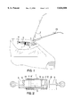
- FIG. 1 depicts the rear of a vehicle with a rear hatch pivoted and arrested by a pneumatic pressure strut, in two different positions;
- FIG. 2 is a view in longitudinal section of an arresting device comprising corrugated tubes which may be brought into frictional engagement with each other;
- FIG. 3 is a view in longitudinal section of a sensor-controlled arresting device utilizing frictional engagement
- FIG. 4 depicts a further embodiment of an arresting device utilizing frictional engagement
- FIG. 5 depicts an arresting device provided with an inflatable and deflatable body for establishing frictional engagement.
- FIG. 1 shows an arresting device 1 for a pivotable vehicle lid 2, shown as a rear hatch.
- the arresting device 1 is provided with a pneumatic pressure strut 3 extending between a body 4 of a vehicle shown only partially and the rear hatch 2 thereof, and providing a drive motor for the opening pivotal movement of the hatch 2 up to a terminal position at a maximum pivot angle shown in dashed lines.
- the pneumatic strut 3 is provided with a cylinder 5 as well as a piston slidably movable therein and also with a piston rod 6. As shown, the free end of the cylinder 5 is pivotally connected to the rear hatch 2, and the free end of the piston rod 6 is pivotally connected to the body 4.
- the rear hatch 2 Upon release of a trunk lock, the rear hatch 2 is automatically pivoted upwardly by the pneumatic pressure strut 3 by the increased gas pressure in the cylinder section driving the piston, thus extending the piston rod 6.
- the arresting device 1 mounted outside of the cylinder 5 of the pneumatic strut limits the extension of the piston rod 6 defining the pivot angle to several positions before ahead of the maximally possible pivot angle is reached, as depicted by the rear hatch 2 shown in solid line.
- an arresting member 7 (7', 7") of the arresting device 1 is positioned adjacent to the cylinder 5 of the pneumatic strut 3 and may be moved into frictional engagement with a complementary member 8 (8', 8") which is movable by the piston rod 6.
- the complementary member 8 is arranged within a tube 9 which is mounted on the piston rod 6 and embraces the cylinder 5 of the pneumatic strut.
- FIG. 2 which depicts the structure of the arresting device of FIG. 1 in greater detail (rotated by 180 degrees)
- a tubular arresting member 7' is affixed to the cylinder 5.
- the tubular member 7' is provided with a corrugated outer surface portion 10 extending in the direction of the longitudinal axis of the cylinder, and the complementary member 8' is provided with matching corrugations formed in a surface portion 11 of the tube 9.
- the piston rod 6 is moved out of the cylinder 5 of the pneumatic strut the tube 9 moves with it and, by its surface portion 11 will move into engagement with the corrugated surface section 10 thus interrupting further outward movement.
- the complementary member 8' Only by use of greater force, such as an upward push of the rear hatch 2 by a user, may the complementary member 8' be pulled further over the arresting member 7', snapping or ratcheting into the respective opposite corrugations as it moves over the arresting member 7'.
- the surface portion 11 in the tube 9 will resiliently yield.
- the rear hatch 2 may be arrested in as many different angular positions as there are abutments or corrugations in the complementary surface portions 10 and 11. The terminal position with the largest pivot angle and greatest frictional overlap of the surface portions 10 and 11 is attainable by moving the arresting member 7' relative to the cylinder 5.
- the arresting member 7' may be threadedly 12,13 connected to the cylinder 5 the cylinder to facilitate its rotation and, hence, axial displacement arresting member 7' is provided with a sleeve 14 extending in the direction of the free end of the cylinder 5 out of the tube 9 where it is knurled, as shown at 15 After adjustment, the arresting member 7' will self-lock.
- the arresting member 7' By moving the arresting member 7' to the left as seen in the drawing, the extending movement of the piston rod 6 would terminate sooner, thus leading to a smaller pivot angle of the rear hatch 2. Adjusting the maximum desired pivot angle of the rear hatch would also be possible, of course by similary connecting the complementary member 8' on the piston rod 6.
- FIGS. 3, 4, and 5 depict arresting devices 1 in which arresting members 7" are associated with the cylinder 5 of the pneumatic pressure strut, and in which a tube 9 and the complementary arresting member 8" are affixed to the piston rod 6.
- the piston rod 6 may in these embodiments be arrested by frictional engagement of an arresting member 7" which is provided with a power-driven frictional breading surface.
- FIG. 3 depicts an arresting device 1 in which the cylinder 5 of the pneumatic strut is provided with a power-driver arresting member 7" it includes a stationary chuck 16 and a movable chuck 18 connected to the stationary chuck 16 by tension springs 17. Between them, the chucks 16 and 18 form a conical recess 19 in which is seated an expander chuck or sunk provided with a conical 21 bottom 20 matching the conical recess between the chucks 16 and 18.
- the surface of the chuck 21 opposite the cone 20 constitutes a frictional surface 22 which may be moved into for engagement with a complementary frictional surface 23 provided at the interior wall of the tube 9.
- a switch 24 has to be actuated to close an electric circuit for energizing a solenoid 25 which, in turn, attracts the movable chuck 18 and pulls it away from the stationary chuck 16. This causes the conical recess to become wider and the expander chuck 21 to move out of its engagement with frictional surface 23, thus no longer blocking movement of the tube 9 and the piston rod 6.
- the circuit may be designed in such a manner that a sensor 26 (FIG.
- the switch 24 could be designed to be switched by an actuator in the handle of the rear hatch 2 or be replaced or supplemented by from a sensor, responding to the hand of a user approaches the handle.
- Such a circuit could also be the rear hatch against burglaries whenever current or the engine of the vehicle is turned off, by forcibly arresting the piston rod of the cylinder of the pneumatic strut.
- FIG. 4 depicts an embodiment similar to the one of FIG. 3, with the arresting member 7" on the pneumatic strut cylinder 5 being provided with a frictional component 27 biased into engagement with a complementary frictional surface 23 by a pressure spring 28.
- the spring 28 may be retracted from the complementary frictional surface 23 by a solenoid 25, thus allowing the tube 9 and the piston rod 6 to move and the rear hatch to pivot.
- FIG. 5 depicts a structure of the arresting device 1 in which the arresting member 7" is an inflatable body 29 attached to the cylinder 5 of the pneumatic strut and which, for arresting the tube 9 and the piston rod 6, may be filled with a fluid to increase its circumference for engagement with the tube 9, thus frictionally preventing further movement thereof.
- a valve 30 is provided at the input of the inflatable body 29.
- the valve 30 in one of its settings cause the body 29 to be inflated , and in another setting it causes it to be deflated.
- a sensor 26 may be provided in addition to the switch 24.
Landscapes
- Engineering & Computer Science (AREA)
- General Engineering & Computer Science (AREA)
- Mechanical Engineering (AREA)
- Fluid-Damping Devices (AREA)
- Superstructure Of Vehicle (AREA)
- Actuator (AREA)
Abstract
An upwardly pivotable vehicle lid is provided with a pneumatic pressure strut intermediate body and lid, as an opening drive for the pivot movement into a terminal position having a maximum pivot angle, with the extending movement of a piston rod out of the pneumatic strut cylinder defining the pivot angle being limitable in a plurality of positions ahead of the maximally possible pivot angle by an arresting device mounted outside of the cylinder. The arresting device includes an arresting member positioned on the cylinder of the pneumatic pressure strut and movable into frictional engagement with a complementary member movable by the piston rod of the pneumatic strut.
Description
This is an application pursuant to 35 U.S.C. 371 of International Application PCT/DE95/01689 filed 30 Nov. 1995 published as WO96/17182 Jun. 6, 1996.
The invention, in general, relates to an arresting device for a pivotable lid of a vehicle and more particularly, to a device selectively limiting the extent to which a vehicular door may be opened.
It is commonly known to accomplish the opening movement of a vehicle lid, such as the lid of a trunk (boot) or hood (bonnet) by means of a pneumatic pressure strut. A soon as the lid is unlatched it is pushed upwardly by the force of the pneumatic strut, until it has reached its maximum open terminal position.
A pneumatic pressure strut having a lever associated with it which is arrestable at various lengths at an arresting device is known from German patent DE 43 02 502 C.. (as well as German laid-open patent specification DE 43 06 882 A1). In the arrangements disclosed therein the piston rod of the pneumatic strut is concurrently maintained at the corresponding extended positions. The lever extends in parallel to the pneumatic strut across the entire surface of the rear hatch and is latched by a complex centrifugal element when the hatch is manually stopped during its upward pivoting movement. If it is not stopped in this manner, the hatch will pivot upwardly to the full extensible length of the pneumatic strut.
In German utility model DE 89 15 891 U, there is described a pneumatic pressure strut having a sleeve pushed over its cylinder which sleeve may releasably be arrested on the cylinder in two positions. This does not affect the length to which the piston rod may be extended.
The extension lever at one end of a pneumatic pressure strut described in German laid-open patent specification DE 40 00 862 Al allows for but one additional open pivotal position of a rear hatch.
Changing in the length of a fully extended pneumatic pressure strut is also known from German utility model DE 78 33 766 U and laid-open patent specification DE 41 07 382 A1, in which the end of a piston rod is slidable in a connecting threaded sleeve with either the piston rod or the threaded sleeve having to be rotated, and following adjustment, further rotation has to be prevented. This does not provide for a simple way of arresting in different positions.
From German patent DE 25 55 062 C3 an arresting device for the rear hatch of a vehicle is known which includes a pneumatic pressure strut, the piston of which may be arrested at different extended positions relative to the length of a cylinder, thus maintaining the rear hatch in different open positions. For this purpose, the usual piston of a common pneumatic strut has been altered in a complex manner by the addition to the piston, within the cylinder, of a force-actuated latching member, for controlling the latching. For this type of application, the use of commercially available pneumatic pressure struts at vehicle rear hatches is then no longer possible.
Changing the angular disposition of a hatch moved by a pneumatic strut by means of a telescoping tube extendible from a cylinder is known from German laid-open specification 32 25 974 A1.
It is an object of the invention to make an arresting device in which a piston rod may be arrested at the cylinder by simple means and whereby an unintentional excessive pivotal opening movement of the rear hatch may be prevented.
The arresting device in accordance with the invention makes possible movement of different lengths of the piston rod of a pneumatic pressure strut for stopping a vehicle hatch, when necessary, before it has reached its maximum open angular disposition. For this purpose, a commercially available and, therefore, inexpensive pneumatic strut may be utilized. The frictional connection of an arresting member arranged on the cylinder to a complementary member movable with the piston rod leads to a simple and, therefore, economic structure which because of its small size does not interfere with the vehicle hatch. In the manually actuable version, the vehicle hatch is stopped before reaching its maximum opening angle and may be moved into its maximum opening position in a controlled manner by a person deliberately applying a greater force. In a sensor controlled version, the lid is stopped at a reduced angular disposition when a wall or other object comes too close to the edge of the pivoting vehicle hatch, thus preventing it from being damaged. In such an arrangement, a person not wanting the largest opening, because he would have difficulties moving the hatch down again, for instance, could prevent the maximum pivotal opening by affecting the sensor.
The arresting member and the complementary member required for the frictional connection may be arranged for sliding movement at different positions of the strut cylinder and the piston rod, respectively, so that the maximum values of the arresting positions may be adjustable along the axis of the strut cylinder and accomodate the structure of the vehicle. The frictional connection of arresting member and complementary member is simplified by affixing the complementary member opposite the arresting member on a tube which embraces the strut cylinder at a predetermined spacing therefrom. In fact, the frictional connection may be established by the interior surface of the tube acting as the complementary member.
A frictional connection between the arresting and complementary member may be provided by two corrugated tubes which move into engagement with each other at different positions of the piston rod and initially stop the movement of the piston rod. Thereafter, extending the piston rod further, up to its maximum, becomes possible only with greater force and by the resilient yielding of at least one of the corrugated tubes. The increasing overlap of the corrugated tubes or the increasing number of ratcheting interlocks, as the case may be, leads to a noticeable increase of the force necessary for movement into the terminal position. The increase in actuation force signals to a user that the greatest pivot angle of the vehicle lid is approaching.
The frictional engagement between the arresting member and the complementary member may also be established by sliding one of the members in the direction of the other. In such an arrangement a positive abutment or a frictional abutment may be provided. This movement of the members toward each other may be accomplished by simple components, such as a spring or a magnet, or by a valve-controlled filling of an inflatable body. A sensor may be positioned at the hatch of the vehicle which, as an edge of the hatch approaches a stationary obstacle, for instance, initiates this movement to bring about timely stopping of the vehicle hatch. Also, a switch may be provided at the handle of a vehicle hatch for arresting or releasing movement of the hatch. Such a switch may for instance also be, actuated by the sensor as a hand of a user approaches the handle.
Further advantages and embodiments are set forth in the subclaims and in the description.
The invention will be described with reference to a drawing, in which:
FIG. 1 depicts the rear of a vehicle with a rear hatch pivoted and arrested by a pneumatic pressure strut, in two different positions;
FIG. 2 is a view in longitudinal section of an arresting device comprising corrugated tubes which may be brought into frictional engagement with each other;
FIG. 3 is a view in longitudinal section of a sensor-controlled arresting device utilizing frictional engagement;
FIG. 4 depicts a further embodiment of an arresting device utilizing frictional engagement; and
FIG. 5 depicts an arresting device provided with an inflatable and deflatable body for establishing frictional engagement.
FIG. 1 shows an arresting device 1 for a pivotable vehicle lid 2, shown as a rear hatch. The arresting device 1 is provided with a pneumatic pressure strut 3 extending between a body 4 of a vehicle shown only partially and the rear hatch 2 thereof, and providing a drive motor for the opening pivotal movement of the hatch 2 up to a terminal position at a maximum pivot angle shown in dashed lines. As usual, the pneumatic strut 3 is provided with a cylinder 5 as well as a piston slidably movable therein and also with a piston rod 6. As shown, the free end of the cylinder 5 is pivotally connected to the rear hatch 2, and the free end of the piston rod 6 is pivotally connected to the body 4. Upon release of a trunk lock, the rear hatch 2 is automatically pivoted upwardly by the pneumatic pressure strut 3 by the increased gas pressure in the cylinder section driving the piston, thus extending the piston rod 6. To prevent sudden or abrupt pivoting of the hatch 2 into its terminal position which may cause it to collide with an obstacle, such as the ceiling of a garage, the arresting device 1 mounted outside of the cylinder 5 of the pneumatic strut limits the extension of the piston rod 6 defining the pivot angle to several positions before ahead of the maximally possible pivot angle is reached, as depicted by the rear hatch 2 shown in solid line.
To achieve a compact structure near the pneumatic strut 3 and as shown in greater detail in the ensuing figures, an arresting member 7 (7', 7") of the arresting device 1 is positioned adjacent to the cylinder 5 of the pneumatic strut 3 and may be moved into frictional engagement with a complementary member 8 (8', 8") which is movable by the piston rod 6. The complementary member 8 is arranged within a tube 9 which is mounted on the piston rod 6 and embraces the cylinder 5 of the pneumatic strut.
In the embodiment of FIG. 2 which depicts the structure of the arresting device of FIG. 1 in greater detail (rotated by 180 degrees), a tubular arresting member 7' is affixed to the cylinder 5. The tubular member 7' is provided with a corrugated outer surface portion 10 extending in the direction of the longitudinal axis of the cylinder, and the complementary member 8' is provided with matching corrugations formed in a surface portion 11 of the tube 9. As the piston rod 6 is moved out of the cylinder 5 of the pneumatic strut the tube 9 moves with it and, by its surface portion 11 will move into engagement with the corrugated surface section 10 thus interrupting further outward movement. Only by use of greater force, such as an upward push of the rear hatch 2 by a user, may the complementary member 8' be pulled further over the arresting member 7', snapping or ratcheting into the respective opposite corrugations as it moves over the arresting member 7'. To limit the force required for the contining movement, the surface portion 11 in the tube 9 will resiliently yield. Depending upon the number of abutments or corrugations in the complementary surface portions 10 and 11, it is possible. The rear hatch 2 may be arrested in as many different angular positions as there are abutments or corrugations in the complementary surface portions 10 and 11. The terminal position with the largest pivot angle and greatest frictional overlap of the surface portions 10 and 11 is attainable by moving the arresting member 7' relative to the cylinder 5. To this end, the arresting member 7' may be threadedly 12,13 connected to the cylinder 5 the cylinder to facilitate its rotation and, hence, axial displacement arresting member 7' is provided with a sleeve 14 extending in the direction of the free end of the cylinder 5 out of the tube 9 where it is knurled, as shown at 15 After adjustment, the arresting member 7' will self-lock. By moving the arresting member 7' to the left as seen in the drawing, the extending movement of the piston rod 6 would terminate sooner, thus leading to a smaller pivot angle of the rear hatch 2. Adjusting the maximum desired pivot angle of the rear hatch would also be possible, of course by similary connecting the complementary member 8' on the piston rod 6.
FIGS. 3, 4, and 5 depict arresting devices 1 in which arresting members 7" are associated with the cylinder 5 of the pneumatic pressure strut, and in which a tube 9 and the complementary arresting member 8" are affixed to the piston rod 6. The piston rod 6 may in these embodiments be arrested by frictional engagement of an arresting member 7" which is provided with a power-driven frictional breading surface.
FIG. 3 depicts an arresting device 1 in which the cylinder 5 of the pneumatic strut is provided with a power-driver arresting member 7" it includes a stationary chuck 16 and a movable chuck 18 connected to the stationary chuck 16 by tension springs 17. Between them, the chucks 16 and 18 form a conical recess 19 in which is seated an expander chuck or sunk provided with a conical 21 bottom 20 matching the conical recess between the chucks 16 and 18. The surface of the chuck 21 opposite the cone 20 constitutes a frictional surface 22 which may be moved into for engagement with a complementary frictional surface 23 provided at the interior wall of the tube 9. In their normal state, the chuck 16 and the movable chuck 18, bias, the expander chuck 21 against direction of the complementary frictional surface 23 in the tube 9, thus setting the length to which the piston rod 6 can be extended. In order to move the piston rod 6, a switch 24 has to be actuated to close an electric circuit for energizing a solenoid 25 which, in turn, attracts the movable chuck 18 and pulls it away from the stationary chuck 16. This causes the conical recess to become wider and the expander chuck 21 to move out of its engagement with frictional surface 23, thus no longer blocking movement of the tube 9 and the piston rod 6. The circuit may be designed in such a manner that a sensor 26 (FIG. 1) positioned at the rear hatch 2 and connected in parallel to the switch 24 as is well known causes the circuit to open when an obstacle approaches, to deenergize the solensid 25 action. This causes the expander chuck 21 and its frictional surface 22 to be moved against the complementary frictional surface 23 in the tube 9 and the extending movement of the piston rod 6 to be arrested. Furthermore, the switch 24 could be designed to be switched by an actuator in the handle of the rear hatch 2 or be replaced or supplemented by from a sensor, responding to the hand of a user approaches the handle. Such a circuit could also be the rear hatch against burglaries whenever current or the engine of the vehicle is turned off, by forcibly arresting the piston rod of the cylinder of the pneumatic strut.
FIG. 4 depicts an embodiment similar to the one of FIG. 3, with the arresting member 7" on the pneumatic strut cylinder 5 being provided with a frictional component 27 biased into engagement with a complementary frictional surface 23 by a pressure spring 28. The spring 28 may be retracted from the complementary frictional surface 23 by a solenoid 25, thus allowing the tube 9 and the piston rod 6 to move and the rear hatch to pivot.
FIG. 5 depicts a structure of the arresting device 1 in which the arresting member 7" is an inflatable body 29 attached to the cylinder 5 of the pneumatic strut and which, for arresting the tube 9 and the piston rod 6, may be filled with a fluid to increase its circumference for engagement with the tube 9, thus frictionally preventing further movement thereof. A valve 30 is provided at the input of the inflatable body 29. By a motor 31 actuated by a switch 24, the valve 30 in one of its settings cause the body 29 to be inflated , and in another setting it causes it to be deflated. Here, too, a sensor 26 may be provided in addition to the switch 24.
Claims (17)
1. An apparatus for controlling the opening movement of a door hinged to the body of a vehicle, comprising:
first and second elongate members adapted to be respectively pivotally connected to the door and the body and telescopingly movable relative to each other between a first length at which the door is closely adjacent to the body and a second length at which the door is pivoted away from the body to a maximum;
means on the exterior of one of the first and second elongate members for generating friction;
means on the interior of the other of the first and second elongate members for engaging the friction generating means before the first and second elongate members reach the second length thereby limiting opening movement of the door to less than the maximum.
2. The apparatus of claim 1, wherein one of the first and second elongate members is the cylinder and the other of the first and second members is the piston-driven rod of a gas strut.
3. The apparatus of claim 2, wherein the friction generating and engaging means comprises means for forming a substantially resilient surface having a plurality of axially disposed complementary male and female undulationist.
4. The apparatus of claim 3, wherein the resilient surface forming means comprises tubular means provided with corrugated axial portions.
5. The apparatus of claim 4, wherein the position of at least one of the friction generating and the engaging means is axially adjustable relative to the first and second elongate members.
6. The apparatus of claim 6, wherein at least one of the friction generating and engaging means is threadedly connected to one of the first and second elongate members.
7. The apparatus of claim 1, wherein the friction generating means comprises a member having a frictional front surface movable substantially normal to at least one of the first and second elongate members and the engaging means comprises a friction surface on the other of the first and second elongate members opposite the friction front surface member.
8. The apparatus of claim 7, wherein the friction front surface member comprises resilient means for biasing the friction front surface into engagement with the friction surface and solenoid means for selectively moving the friction front surface out of engagement with the friction surface.
9. The apparatus of claim 8, wherein the solenoid means comprises a conical recess driveable between first and second widths and wherein the friction front surface means comprises a conical section seated in the conical recess.
10. The apparatus of claim 8, wherein the solenoid means comprises annular coil means and wherein the friction front surface means comprises a plunger of the solenoid means.
11. The apparatus of claim 8, wherein the solenoid means is energizable by manually actuable switch means.
12. The apparatus of claim 11, wherein the switch means comprises proximity sensor means.
13. The apparatus of claim 11, wherein the switch means is provided with parallel connected proximity sensor means.
14. The apparatus of claim 1, wherein the friction generating means comprises selectively inflatable means mounted on one of the first and second elongate means.
15. The apparatus of claim 14, wherein the selectively inflatable means is provided with valve means moveable by a motor into a first state for inflating the inflatable means and into a second state for deflating the inflatable means.
16. The apparatus of claim 15, wherein the motor is energizable by manually actuable switch means.
17. The apparatus of claim 16, wherein the switch means is provided with parallel connected proximity sensor means.
Applications Claiming Priority (3)
| Application Number | Priority Date | Filing Date | Title |
|---|---|---|---|
| DE4442547.3 | 1994-11-30 | ||
| DE19944442547 DE4442547C1 (en) | 1994-11-30 | 1994-11-30 | Locking device for a hinged vehicle flap |
| PCT/DE1995/001689 WO1996017182A1 (en) | 1994-11-30 | 1995-11-30 | Locking device for liftable hatch or engine hood of vehicles |
Publications (1)
| Publication Number | Publication Date |
|---|---|
| US5836050A true US5836050A (en) | 1998-11-17 |
Family
ID=6534499
Family Applications (1)
| Application Number | Title | Priority Date | Filing Date |
|---|---|---|---|
| US08/619,664 Expired - Fee Related US5836050A (en) | 1994-11-30 | 1995-11-30 | Apparatus for controlling the opening movement of a vehicle door |
Country Status (3)
| Country | Link |
|---|---|
| US (1) | US5836050A (en) |
| DE (1) | DE4442547C1 (en) |
| WO (1) | WO1996017182A1 (en) |
Cited By (15)
| Publication number | Priority date | Publication date | Assignee | Title |
|---|---|---|---|---|
| US6367123B1 (en) * | 1998-10-09 | 2002-04-09 | Illinois Tool Works Inc. | Vehicle lid hinge |
| US6397434B1 (en) * | 2000-04-19 | 2002-06-04 | Itw Limited | Vehicle lid hinge |
| US6557924B2 (en) * | 2001-04-20 | 2003-05-06 | Stabilus Gmbh | Actuating system for a hatch or similar hinged structure |
| US6755458B1 (en) * | 2000-09-29 | 2004-06-29 | Intier Automotive Closures Inc. | Liftgate force control |
| EP1070818A3 (en) * | 1999-07-19 | 2005-08-03 | Volkswagen Aktiengesellschaft | Hinge for a liftable flap of a vehicle body |
| US20060130274A1 (en) * | 2004-12-22 | 2006-06-22 | Dr.Ing. H.C.F. Porsche Ag | Door stopper for a motor vehicle door and motor vehicle door for a motor vehicle with a door stopper of this type |
| US20080030045A1 (en) * | 2006-08-07 | 2008-02-07 | Volkswagen Of America, Inc. | Door system for a motor vehicle and method for operating a door system |
| US20080168600A1 (en) * | 2007-01-16 | 2008-07-17 | Juergen Gross | Shower device |
| US20100154307A1 (en) * | 2008-12-24 | 2010-06-24 | Gm Global Technology Operations, Inc. | Damping assembly for reducing vibrations in a latch for a vehicle door and a method |
| JP2012021559A (en) * | 2010-07-13 | 2012-02-02 | Nifco Inc | Buffer device |
| US20130055639A1 (en) * | 2011-09-07 | 2013-03-07 | GM Global Technology Operations LLC | Motor vehicle with a rear flap |
| US20140150207A1 (en) * | 2011-07-11 | 2014-06-05 | Piolax, Inc | Vehicle opening/closing member damper apparatus and vehicle opening/closing member stopper apparatus |
| US8893840B2 (en) | 2011-06-27 | 2014-11-25 | Caterpillar Inc. | Engine enclosure door |
| US20190077234A1 (en) * | 2016-02-09 | 2019-03-14 | Hi-Lex Corporation | Device for opening and closing opening/closing body |
| US11299923B2 (en) * | 2015-02-24 | 2022-04-12 | Brose Fahrzeugteile GmbH SE & Co. Kommanditgesselschaft, Bamberg | Drive arrangement for a closure element of a motor vehicle |
Families Citing this family (20)
| Publication number | Priority date | Publication date | Assignee | Title |
|---|---|---|---|---|
| DE19806498A1 (en) * | 1998-02-17 | 1999-08-26 | Mannesmann Sachs Ag | Lockable vibration damper for motor vehicles |
| DE19819377C2 (en) * | 1998-04-30 | 2000-02-10 | Stabilus Gmbh | Piston-cylinder unit with sliding connecting element |
| DE19934764C2 (en) * | 1999-07-23 | 2002-03-28 | Audi Ag | Gas compression spring element |
| DE19957198B4 (en) * | 1999-11-27 | 2008-01-31 | Volkswagen Ag | Closing device for a flap with a closing bolt cover |
| DE10058432B4 (en) * | 2000-11-24 | 2005-12-15 | Audi Ag | Door lock of a motor vehicle door |
| DE10225887A1 (en) * | 2002-06-11 | 2004-01-08 | Daimlerchrysler Ag | Motor vehicle with outwardly pivotable door or flap mounted on rear end has at least one actuating device integrated into electronic key for starting and/or opening and/or closing the vehicle |
| DE10238448C5 (en) * | 2002-08-22 | 2008-01-03 | Daimlerchrysler Ag | Variable gas spring |
| DE10349031A1 (en) * | 2003-10-22 | 2005-05-25 | Siemens Ag | Servo drive for rear hatch door in vehicle has a brake operating on the door or on the reduction gearing or on the motor to secure the door in an intermediate setting between fully open and closed |
| US8118285B2 (en) | 2004-07-01 | 2012-02-21 | Avm Industries | Gas spring with integrated lead screw drive |
| DE102005015667A1 (en) * | 2005-04-06 | 2006-10-12 | Daimlerchrysler Ag | Locking catch for vehicle door has a piston rod sliding in a cylinder and fitted with a ratchet grip for securing the door in several open settings |
| DE102006054410A1 (en) * | 2006-11-18 | 2008-05-21 | Conti Temic Microelectronic Gmbh | Swiveling body part with adjustable maximum opening angle |
| DE102008017770A1 (en) * | 2008-04-08 | 2009-10-15 | GM Global Technology Operations, Inc., Detroit | Locking device for damping element, comprises piston rod, which is movably stored in cylinder against hydraulic or pneumatic pressure, and locking medium is provided, which is connected with cylinder |
| AT506903B1 (en) * | 2008-05-19 | 2013-09-15 | Blum Gmbh Julius | DAMPING DEVICE FOR FURNITURE OR FURNITURE FITTINGS |
| FR2939167A1 (en) * | 2008-12-03 | 2010-06-04 | Peugeot Citroen Automobiles Sa | Motorized opening frame e.g. lateral sliding/side door, opening and closing controlling device for motor vehicle i.e. car, has adjustment units adjusting degree of frame beyond predefined opening position according to command of user |
| DE102010024994B4 (en) | 2010-06-24 | 2012-06-14 | Günther Zimmer | Pneumatic decelerator with constant power |
| DE102010026128B4 (en) | 2010-07-05 | 2013-03-14 | Günther Zimmer | Ausstellvorrichtung with friction element |
| CN103410906A (en) * | 2013-08-04 | 2013-11-27 | 王振民 | Electric gas spring |
| DE102015119505B4 (en) * | 2015-07-21 | 2022-12-08 | Inventus Engineering Gmbh | Door component with a controllable damper device |
| IT201700033595A1 (en) * | 2017-03-27 | 2018-09-27 | Vapsint S R L | SHOCK ABSORBER DEVICE |
| CN111749568B (en) * | 2019-03-27 | 2022-04-26 | 麦格纳覆盖件有限公司 | Balance mechanism with friction |
Citations (13)
| Publication number | Priority date | Publication date | Assignee | Title |
|---|---|---|---|---|
| US3711892A (en) * | 1969-11-07 | 1973-01-23 | Meteor Res Ltd | Closure counterbalance |
| FR2335136A7 (en) * | 1975-12-12 | 1977-07-08 | Stabilus Gmbh | MECHANICAL LOCKING PNEUMATIC SPRING |
| US4339843A (en) * | 1978-03-20 | 1982-07-20 | Reading-Dorma Closer Corporation | Door closer with assist or door operating features |
| US4564973A (en) * | 1982-10-22 | 1986-01-21 | Dorma-Baubeschlag Gmbh & Co. Kg. | Door closing device having an adjustable length arm |
| US4596383A (en) * | 1984-02-21 | 1986-06-24 | Gas Spring Company, Division Of Fichtel & Sachs Industries, Inc. | Gas spring with secondary lock |
| US4807855A (en) * | 1987-07-24 | 1989-02-28 | Suspa, Incorporated | Gas cylinder plunger lock |
| US4925230A (en) * | 1988-06-27 | 1990-05-15 | General Motors Corporation | Hold open device for compartment lid |
| DE9308253U1 (en) * | 1993-06-02 | 1993-09-23 | Shen Wei Hong | AIR PRESSURE SPRING FOR TELESCOPIC SUPPORTS |
| EP0568006A1 (en) * | 1992-04-27 | 1993-11-03 | Stabilus GmbH | Telescopic positioning device |
| JPH06147247A (en) * | 1992-11-07 | 1994-05-27 | Tokico Ltd | Hydraulic buffer |
| EP0602917A1 (en) * | 1992-12-15 | 1994-06-22 | Camloc (U.K.) Limited | Strut with adjustable friction means |
| US5507070A (en) * | 1994-08-31 | 1996-04-16 | Enidine, Inc. | Mechanism for closing a lid |
| US5592780A (en) * | 1995-06-07 | 1997-01-14 | Checkovich; Peter | Door position controlling apparatus |
Family Cites Families (9)
| Publication number | Priority date | Publication date | Assignee | Title |
|---|---|---|---|---|
| DE3225974A1 (en) * | 1982-07-10 | 1984-01-19 | Daimler-Benz Ag, 7000 Stuttgart | GAS SPRING |
| DE8316231U1 (en) * | 1983-06-03 | 1983-10-20 | Herlan, Egon, 8590 Marktredwitz | DEVICE FOR KEEPING THE TAILGATE OR TRUNK COVER OF A MOTOR VEHICLE |
| DE3519203A1 (en) * | 1985-01-19 | 1986-07-24 | Dr.Ing.H.C. F. Porsche Ag, 7000 Stuttgart | ACTUATING DEVICE FOR A DOOR OF A MOTOR VEHICLE |
| DE3914991A1 (en) * | 1989-05-06 | 1991-02-14 | Bauer Fritz & Soehne Ohg | GAS SPRING |
| DE4000862A1 (en) * | 1990-01-13 | 1991-07-18 | Stabilus Gmbh | Rear door for hatch-back car - has additional link to attach it to gas spring to hold it in either of two open positions |
| DE4107382A1 (en) * | 1991-03-08 | 1992-09-10 | Stabilus Gmbh | Gas spring for car body installations - has radially resilient holding clamps with moulded area to engage in fixed component |
| DE4224132C2 (en) * | 1992-07-22 | 2002-11-14 | Stabilus Gmbh | Door locking system |
| DE4302502C1 (en) * | 1993-01-29 | 1994-05-26 | Daimler Benz Ag | Movable tailgate for motor car - has centrifugal force-controlled holding device which can fix it in closed or open positions |
| DE4306772C2 (en) * | 1993-03-04 | 1995-08-17 | Daimler Benz Ag | Motor vehicle with a movable body part |
-
1994
- 1994-11-30 DE DE19944442547 patent/DE4442547C1/en not_active Expired - Lifetime
-
1995
- 1995-11-30 WO PCT/DE1995/001689 patent/WO1996017182A1/en active Application Filing
- 1995-11-30 US US08/619,664 patent/US5836050A/en not_active Expired - Fee Related
Patent Citations (14)
| Publication number | Priority date | Publication date | Assignee | Title |
|---|---|---|---|---|
| US3711892A (en) * | 1969-11-07 | 1973-01-23 | Meteor Res Ltd | Closure counterbalance |
| FR2335136A7 (en) * | 1975-12-12 | 1977-07-08 | Stabilus Gmbh | MECHANICAL LOCKING PNEUMATIC SPRING |
| US4078779A (en) * | 1975-12-12 | 1978-03-14 | Stabilus Gmbh | Pneumatic spring with manually releasable stop |
| US4339843A (en) * | 1978-03-20 | 1982-07-20 | Reading-Dorma Closer Corporation | Door closer with assist or door operating features |
| US4564973A (en) * | 1982-10-22 | 1986-01-21 | Dorma-Baubeschlag Gmbh & Co. Kg. | Door closing device having an adjustable length arm |
| US4596383A (en) * | 1984-02-21 | 1986-06-24 | Gas Spring Company, Division Of Fichtel & Sachs Industries, Inc. | Gas spring with secondary lock |
| US4807855A (en) * | 1987-07-24 | 1989-02-28 | Suspa, Incorporated | Gas cylinder plunger lock |
| US4925230A (en) * | 1988-06-27 | 1990-05-15 | General Motors Corporation | Hold open device for compartment lid |
| EP0568006A1 (en) * | 1992-04-27 | 1993-11-03 | Stabilus GmbH | Telescopic positioning device |
| JPH06147247A (en) * | 1992-11-07 | 1994-05-27 | Tokico Ltd | Hydraulic buffer |
| EP0602917A1 (en) * | 1992-12-15 | 1994-06-22 | Camloc (U.K.) Limited | Strut with adjustable friction means |
| DE9308253U1 (en) * | 1993-06-02 | 1993-09-23 | Shen Wei Hong | AIR PRESSURE SPRING FOR TELESCOPIC SUPPORTS |
| US5507070A (en) * | 1994-08-31 | 1996-04-16 | Enidine, Inc. | Mechanism for closing a lid |
| US5592780A (en) * | 1995-06-07 | 1997-01-14 | Checkovich; Peter | Door position controlling apparatus |
Cited By (20)
| Publication number | Priority date | Publication date | Assignee | Title |
|---|---|---|---|---|
| US6367123B1 (en) * | 1998-10-09 | 2002-04-09 | Illinois Tool Works Inc. | Vehicle lid hinge |
| EP1070818A3 (en) * | 1999-07-19 | 2005-08-03 | Volkswagen Aktiengesellschaft | Hinge for a liftable flap of a vehicle body |
| US6397434B1 (en) * | 2000-04-19 | 2002-06-04 | Itw Limited | Vehicle lid hinge |
| US6755458B1 (en) * | 2000-09-29 | 2004-06-29 | Intier Automotive Closures Inc. | Liftgate force control |
| US6557924B2 (en) * | 2001-04-20 | 2003-05-06 | Stabilus Gmbh | Actuating system for a hatch or similar hinged structure |
| US7516514B2 (en) * | 2004-12-22 | 2009-04-14 | Dr. Ing. H.C.F. Porsche Aktiengessellschaft | Door stopper for a motor vehicle door and motor vehicle door for a motor vehicle with a door stopper of this type |
| US20060130274A1 (en) * | 2004-12-22 | 2006-06-22 | Dr.Ing. H.C.F. Porsche Ag | Door stopper for a motor vehicle door and motor vehicle door for a motor vehicle with a door stopper of this type |
| US20080030045A1 (en) * | 2006-08-07 | 2008-02-07 | Volkswagen Of America, Inc. | Door system for a motor vehicle and method for operating a door system |
| US8104111B2 (en) | 2007-01-16 | 2012-01-31 | Hansgrohe Ag | Shower device |
| US20080168600A1 (en) * | 2007-01-16 | 2008-07-17 | Juergen Gross | Shower device |
| US20100154307A1 (en) * | 2008-12-24 | 2010-06-24 | Gm Global Technology Operations, Inc. | Damping assembly for reducing vibrations in a latch for a vehicle door and a method |
| US8123262B2 (en) * | 2008-12-24 | 2012-02-28 | GM Global Technology Operations LLC | Damping assembly for reducing vibrations in a latch for a vehicle door |
| JP2012021559A (en) * | 2010-07-13 | 2012-02-02 | Nifco Inc | Buffer device |
| US8893840B2 (en) | 2011-06-27 | 2014-11-25 | Caterpillar Inc. | Engine enclosure door |
| US20140150207A1 (en) * | 2011-07-11 | 2014-06-05 | Piolax, Inc | Vehicle opening/closing member damper apparatus and vehicle opening/closing member stopper apparatus |
| US9493976B2 (en) * | 2011-07-11 | 2016-11-15 | Piolax Inc. | Vehicle opening/closing member damper apparatus and vehicle opening/closing member stopper apparatus |
| US20130055639A1 (en) * | 2011-09-07 | 2013-03-07 | GM Global Technology Operations LLC | Motor vehicle with a rear flap |
| US11299923B2 (en) * | 2015-02-24 | 2022-04-12 | Brose Fahrzeugteile GmbH SE & Co. Kommanditgesselschaft, Bamberg | Drive arrangement for a closure element of a motor vehicle |
| US20190077234A1 (en) * | 2016-02-09 | 2019-03-14 | Hi-Lex Corporation | Device for opening and closing opening/closing body |
| US10675956B2 (en) * | 2016-02-09 | 2020-06-09 | Hi-Lex Corporation | Device for opening and closing opening/closing body |
Also Published As
| Publication number | Publication date |
|---|---|
| DE4442547C1 (en) | 1996-06-05 |
| WO1996017182A1 (en) | 1996-06-06 |
Similar Documents
| Publication | Publication Date | Title |
|---|---|---|
| US5836050A (en) | Apparatus for controlling the opening movement of a vehicle door | |
| US5839719A (en) | Pneumatic strut for a motor vehicle with an adjustable limit position | |
| US5547040A (en) | Automatic step for recreational vehicles | |
| EP3416870B1 (en) | Motor-adjustable steering column for a motor vehicle | |
| EP0753684B1 (en) | Gas spring | |
| US5799759A (en) | Hydraulic strut for a motor vehicle | |
| US6345549B1 (en) | Line adjustment actuator | |
| US5238213A (en) | Extendable support | |
| US4813100A (en) | Closure check | |
| KR20080112962A (en) | Air spring for vehicle closure | |
| JP2001510733A (en) | Pneumatic-operated hydraulic rivet gun | |
| US6634627B1 (en) | Pneumatic spring with adjustable stop for stroke control | |
| US9702176B2 (en) | Spring loaded actuator assembly | |
| US20060152033A1 (en) | Convertible roof bow control mechanism | |
| DE10324514A1 (en) | Bumper for motor vehicle, comprises a front spoiler, position of which can be changed along an inclined plane relative to bumper | |
| GB2036247A (en) | A spring device with lost-motion transmission | |
| US7682032B2 (en) | Apparatus for pivoting a mirror assembly | |
| US7065923B2 (en) | Method and apparatus for breakaway mounting of security gate to drive mechanism | |
| EP1172324B1 (en) | Hydraulic cylinder for telescopic arms | |
| JP2002013347A (en) | Operating device for opening and closing hinge type automobile panel | |
| US4538522A (en) | Cable gripping apparatus having forward and rearward movement capabilities | |
| US5542643A (en) | Pneumatic ball valve operator | |
| JP2002540365A (en) | Pressure medium operated piston cylinder device with piston rod locking means | |
| US11125297B2 (en) | Adjustment device for a flap assembly and motor vehicle with an adjustment device of this type | |
| US5954315A (en) | Hydraulic spring compressor |
Legal Events
| Date | Code | Title | Description |
|---|---|---|---|
| REMI | Maintenance fee reminder mailed | ||
| LAPS | Lapse for failure to pay maintenance fees | ||
| STCH | Information on status: patent discontinuation |
Free format text: PATENT EXPIRED DUE TO NONPAYMENT OF MAINTENANCE FEES UNDER 37 CFR 1.362 |
|
| FP | Lapsed due to failure to pay maintenance fee |
Effective date: 20021117 |