US5830195A - Couplings for medical cannulae - Google Patents
Couplings for medical cannulae Download PDFInfo
- Publication number
- US5830195A US5830195A US08/687,384 US68738496A US5830195A US 5830195 A US5830195 A US 5830195A US 68738496 A US68738496 A US 68738496A US 5830195 A US5830195 A US 5830195A
- Authority
- US
- United States
- Prior art keywords
- cap
- coupling
- members
- tube
- coupling according
- Prior art date
- Legal status (The legal status is an assumption and is not a legal conclusion. Google has not performed a legal analysis and makes no representation as to the accuracy of the status listed.)
- Expired - Fee Related
Links
Images


Classifications
-
- A—HUMAN NECESSITIES
- A61—MEDICAL OR VETERINARY SCIENCE; HYGIENE
- A61M—DEVICES FOR INTRODUCING MEDIA INTO, OR ONTO, THE BODY; DEVICES FOR TRANSDUCING BODY MEDIA OR FOR TAKING MEDIA FROM THE BODY; DEVICES FOR PRODUCING OR ENDING SLEEP OR STUPOR
- A61M39/00—Tubes, tube connectors, tube couplings, valves, access sites or the like, specially adapted for medical use
- A61M39/22—Valves or arrangement of valves
- A61M39/28—Clamping means for squeezing flexible tubes, e.g. roller clamps
- A61M39/286—Wedge clamps, e.g. roller clamps with inclined guides
-
- A—HUMAN NECESSITIES
- A61—MEDICAL OR VETERINARY SCIENCE; HYGIENE
- A61M—DEVICES FOR INTRODUCING MEDIA INTO, OR ONTO, THE BODY; DEVICES FOR TRANSDUCING BODY MEDIA OR FOR TAKING MEDIA FROM THE BODY; DEVICES FOR PRODUCING OR ENDING SLEEP OR STUPOR
- A61M39/00—Tubes, tube connectors, tube couplings, valves, access sites or the like, specially adapted for medical use
- A61M39/10—Tube connectors; Tube couplings
- A61M39/1011—Locking means for securing connection; Additional tamper safeties
-
- A—HUMAN NECESSITIES
- A61—MEDICAL OR VETERINARY SCIENCE; HYGIENE
- A61M—DEVICES FOR INTRODUCING MEDIA INTO, OR ONTO, THE BODY; DEVICES FOR TRANSDUCING BODY MEDIA OR FOR TAKING MEDIA FROM THE BODY; DEVICES FOR PRODUCING OR ENDING SLEEP OR STUPOR
- A61M39/00—Tubes, tube connectors, tube couplings, valves, access sites or the like, specially adapted for medical use
- A61M39/10—Tube connectors; Tube couplings
- A61M39/16—Tube connectors; Tube couplings having provision for disinfection or sterilisation
- A61M39/165—Shrouds or protectors for aseptically enclosing the connector
-
- A—HUMAN NECESSITIES
- A61—MEDICAL OR VETERINARY SCIENCE; HYGIENE
- A61M—DEVICES FOR INTRODUCING MEDIA INTO, OR ONTO, THE BODY; DEVICES FOR TRANSDUCING BODY MEDIA OR FOR TAKING MEDIA FROM THE BODY; DEVICES FOR PRODUCING OR ENDING SLEEP OR STUPOR
- A61M39/00—Tubes, tube connectors, tube couplings, valves, access sites or the like, specially adapted for medical use
- A61M39/10—Tube connectors; Tube couplings
- A61M2039/1027—Quick-acting type connectors
-
- A—HUMAN NECESSITIES
- A61—MEDICAL OR VETERINARY SCIENCE; HYGIENE
- A61M—DEVICES FOR INTRODUCING MEDIA INTO, OR ONTO, THE BODY; DEVICES FOR TRANSDUCING BODY MEDIA OR FOR TAKING MEDIA FROM THE BODY; DEVICES FOR PRODUCING OR ENDING SLEEP OR STUPOR
- A61M39/00—Tubes, tube connectors, tube couplings, valves, access sites or the like, specially adapted for medical use
- A61M39/10—Tube connectors; Tube couplings
- A61M2039/1033—Swivel nut connectors, e.g. threaded connectors, bayonet-connectors
-
- Y—GENERAL TAGGING OF NEW TECHNOLOGICAL DEVELOPMENTS; GENERAL TAGGING OF CROSS-SECTIONAL TECHNOLOGIES SPANNING OVER SEVERAL SECTIONS OF THE IPC; TECHNICAL SUBJECTS COVERED BY FORMER USPC CROSS-REFERENCE ART COLLECTIONS [XRACs] AND DIGESTS
- Y10—TECHNICAL SUBJECTS COVERED BY FORMER USPC
- Y10S—TECHNICAL SUBJECTS COVERED BY FORMER USPC CROSS-REFERENCE ART COLLECTIONS [XRACs] AND DIGESTS
- Y10S604/00—Surgery
- Y10S604/905—Aseptic connectors or couplings, e.g. frangible, piercable
Definitions
- This invention is concerned with medical equipment, and in particular relates to couplings for connecting cannulae or catheters to a connection tube through which liquid to be administered to a patient is delivered, or fluid to be taken from a patient is collected.
- a catheter tube prefferably equipped, at the end thereof opposite the end which is introduced into the patient, with a moulded plastic connection hub defining a tapered socket of frustoconical configuration.
- This hub constitutes a female coupling member for cooperation with a complementary male member fitted to the end of the connection tube, e.g. of an administration set.
- the male member comprises a tapered frustoconical spigot which is dimensioned to engage with a friction fit in the tapered socket of the catheter hub.
- Another disadvantage of the conventional coupling is that the male and female members are quite small and need to be held in the fingers at or very closely to those surface portions which are contacted by fluid, when engaging and releasing the coupling. This carries with it a risk of infection as bacteria deposited on the plastic members have a tendency to colonise and the bacteria can be carried by the liquid flowing through the coupling into the patient's blood stream. Also, the patient may finger the coupling and cause bacterial contamination.
- the present invention addresses the foregoing problems.
- the present invention resides broadly in a coupling for a medical cannula comprising two members secured against separation by a rotatably tightened part, charactered in that a locking arrangement is provided for locking said part against rotation in the loosening direction.
- the invention provides a coupling for a medical catheter, comprising separate male and female members which are connectable with a push fit, a cap for surrounding the members and rotatable for releasable engagement with one of the members to secure the members against being pulled apart, and means on said cap and said one member for locking the cap against reverse rotation.
- the said one member is the catheter hub and includes a peripheral surface portion provided with ratchet teeth therearound.
- the cap held captive but rotatable on the male member, has an internally threaded section and projecting forwardly therefrom means carrying one or more pawls for engaging the ratchet teeth to retain the cap against rotation in a direction to release the cap.
- the means carrying the pawls is preferably resilient to allow for their disengagement from the ratchet teeth when authorised separation of the coupling is required.
- a coupling for a medical catheter comprising separate male and female members which are connectable with a push fit, a cap for surrounding the members and rotatable for releasable engagement with one of the members to secure the members against being pulled apart, and means extending rearwardly of the cap part engageable with the one member and defining at a position remote therefrom a holding section for holding the cap during connection of the male and female members and rotation of the cap for engaging said cap part with said one member.
- the rearwardly extending means may be fastened to, e.g. be integral with the cap, or it may be a separate component, in which case it can be adjustable and define a shell or housing for enclosing the assembled male and female members, and the cap, to form a barrier against bacterial contaminations.
- the coupling can be completed and secured without need to handle any parts in close proximity to the cooperating portions of the male and female members, the risk of these portions being contacted by bacteria is substantially eliminated.
- a coupling for a medical catheter comprising a female member for cooperation with a male coupling member, a flexible walled tube connected to the female member, and valve means for pinching closed the tube and displacing liquid therein towards the female member for filling the volume occupied by the male member on disconnection of the male member from the female member.
- valve means By virtue of the valve means the liquid remaining in the catheter can be brought to fill the socket of the catheter hub and thereby risk of air passing through the catheter during and immediately after an administration set replacement operation is excluded.
- the valve means can take a variety of different forms and will be operated by initially closing the tube at one position followed by reducing the volume within the tube on the upstream side of this position.
- a coupling for a medical catheter comprising two separate members releasably engageable with each other, and a capsule for defining a substantially sealed enclosure around the engaged coupling members for excluding bacteria from contact therewith.
- the capsule conveniently comprises two parts, e.g. connected by an integral hinge, adapted to engage with a snap fit when applied over the coupled members, and can be capable of being opened only by destruction to thwart any attempt to re-use a capsule which may have become contaminated.
- FIG. 1 is a partly sectioned side elevation of a coupling embodying the invention
- FIG. 2 is a transverse cross section taken along the line II--II in FIG. 1;
- FIG. 3 is a view similar to FIG. 1 showing a modified coupling
- FIG. 4 is a partly sectioned side elevation of another coupling in accordance with the invention.
- FIG. 5 is a transverse section taken along the line V--V in FIG. 4;
- FIG. 6 shows the coupling of FIG. 4 in fully connected condition
- FIG. 7 is a view similar to FIG. 4 illustrating a modified construction
- FIG. 8 is a perspective sketch showing the principles of the modified construction
- FIG. 9 shows an embodiment of a valve mechanism for the female member of a coupling
- FIG. 10 is a transverse section taken along the line X--X of FIG. 9;
- FIG. 11 is a partially cut away scrap view of the member shown in FIG. 9;
- FIG. 12 is a schematic side view of another valve device
- FIG. 13 is a section taken along the line XIII--XIII of FIG. 12;
- FIG. 14 is a plan view of the device of FIG. 12;
- FIG. 15 shows another form of valve device
- FIG. 16 is a longitudinal section through a further female member with a valve device
- FIG. 17 is a perspective view of the member of FIG. 16;
- FIG. 18 is a schematic perspective view of an assembly of couplings and associated valves within a common case
- FIG. 19 is a transverse section through another valve device
- FIG. 20 is a sketch illustrating the mode of operation of the FIG. 19 device
- FIG. 21 is a perspective view of a capsule enclosing a coupling according to the invention.
- FIG. 22 is a perspective view of another capsule
- FIG. 23 illustrates a form of seal which may be incorporated in the capsules
- FIG. 24 is a partial perspective illustration of another capsule
- FIG. 25 shows in open condition another capsule according to the invention.
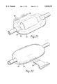
- FIG. 26 shows in perspective another embodiment of a capsule
- FIG. 27 shows the capsule of FIG. 26 in end elevation.
- the coupling assembly illustrated in FIG. 1 comprises a female member 1 in the form of a rigid plastics moulding fixed to the trailing end of a catheter tube (not shown), and a male member 2 attached to a connection tube 3, e.g. leading from a fluid container.
- the female member includes a part 4 defining a tapered socket into which a complementary spigot 5 of the male member is engaged and sealed with a friction push-fit.
- the part 4 is provided with a pair of opposed radially directed lips 6 for engagement by a cap 7 which has a cylindrical part provided with an internal screw thread 8 to enable the cap to be screwed onto the part 4 by cooperation of the lips 6 with the thread.
- the cap has an end wall 9 with a central hole through which the male member 2 passes with a clearance allowing rotation of the cap relative to the male member 2.
- the end wall 9 abuts a flange 10 formed on member 2 and can be held captive by a further projection 11 on the member 2 although this is not essential.
- the coupling is of a construction in practical use and generally known as a "Luer Lock”.
- the female member includes a locking section 12 located between the part 4 and a holding part 13 for gripping the member when connecting and disconnecting the coupling.
- the section 12 has longitudinal ratchet teeth 14 around its periphery as clearly shown in FIG. 2.
- Carried by the cap and attached to the cylindrical part by integral strips 15 or a flexible skirt is an elliptical collar 16 having inwardly directed pawls 17 positioned opposite one another on the smallest diameter of the ellipse.
- the collar is resilient and the pawls 17 engage the ratchet teeth 14 to allow rotation of the cap about the member 1 in the direction (counterclockwise as seen in FIG. 2) corresponding to forward screwing movement of the cap onto the part 4, and to prevent reverse rotation, i.e.
- the coupling is made by pushing the spigot 5 into the socket of part 4, advancing the cap 7 to bring the thread 8 into cooperation with the lips 6, and the pawls 17 into cooperation with the ratchet teeth 14, and screwing the cap onto the part 4 of the female member.
- FIG. 3 shows a modified embodiment wherein the can is formed with an extension 20 directed rearwardly from the wall 9.
- This extension constitutes a finger grip section so that both the can and the female member can be held at locations remote from the spigot 5 and socket part 4, which form the fluid conducting joint between the members, during their connection, and hence risk of contamination by bacteria is reduced.
- the coupling is otherwise as described above in relation to FIGS. 1 and 2.
- An alternative coupling assembly also embodying the invention is shown in FIGS. 4 to 6.
- the male and female members in this embodiment are essentially the same as in the embodiment of FIG. 1, as is the cap 7 except that the pawls 17 are carried at the free ends of resilient arms 22 extending forwardly from the cylindrical cap part.
- An outer housing member or shell 25 is slidably mounted over the male member 2 and includes a forwardly directed cylindrical skirt 26 which surrounds the cap 7 and spigot 5. On the inside of the skirt are longitudinal grooves 27 defining keyways for key elements in the form of radial projections or studs 28 on the cylindrical part of the cap.
- the shell 25 is fast for rotation with the cap 7, but is longitudinally displaceable relative thereto.
- the trailing end of the shell includes a finger grip portion for holding the male member during connection of the assembly.
- the spigot 5 is inserted into the socket and the cap 7 is screwed onto the part 4 by rotating the shell and hence the cap relative to the female part 1.
- the pawls 17 are held free of the ratchet teeth.
- the shell is then displaced forwardly to press the arms 22 inwardly and thereby engage the pawls with the ratchet teeth to lock the shell and cap against rotation in the direction to release the cap, and to bring the leading end of the shell into cooperation with the part 13 of the female member.
- the part 13 has an annular groove for receiving the end of the shell. In this closed position, as shown in FIG. 6, the shell and part 13 define an enclosure surrounding completely the parts forming the fluid connection to deter bacterial contamination of these parts.
- the inner surface of the shell preferably includes an annular groove 29 at the inner end of the keyway grooves 27, the studs 28 being located in this groove when the shell is closed so that the shell can rotate freely in this axial position. It will be understood the shell must be retracted to the position shown in FIG. 4, to release the pawls from the ratchet teeth, before the cap can be unscrewed to release the coupling.
- the locking section 12 could have longitudinal splines with which the pawls engage to prevent rotation of the cap in either direction.
- FIGS. 7 and 8 there is shown a construction in which a longitudinal rib 30 is formed on the inside of the shell and the cap has a dog 31 on its rear wall as well as a longitudinal groove 32.
- the rib 30 engages the dog 31 for rotating the cap to screw it onto the female member, after which the shell 25 is turned back to align the rib 30 with the groove 32 to allow the shell to be advanced to its closed position.
- the forward end of the female member 1 has not been illustrated in FIGS. 1 to 8, but it is preferably provided with a valve device as described below.
- the female member 1 shown in FIG. 9 extends forwardly to define a channel section 30 of Generally rectangular configuration.
- a flexible wailed tube 31 the forward end of which is sealed to the catheter tube 22, and the rear end of which is sealed in a counterbore leading into the socket of part 4.
- Mounted on the channel section 30 is a slider 33 the down-turned sides of which have inturned lips which are received in longitudinal grooves provided in the external surfaces of the channel side walls.
- a pair of laterally spaced lugs 34 on the slider project downwardly into the channel on either side of the tube 31, and are provided with slots through which an axle pin 35 carrying a roller 36 passes.
- the ends of the pin engage in parallel grooves formed on the inside surfaces of the channel side walls and having upper forward sections 37, medial ramp section 38, and lower rear sections 39.
- the roller 36 In a forward position of the slider, the roller 36 is supported above the tube 31 which permits unrestricted flow through the tube.
- the pin 35 When the slider is displaced rearwardly, the pin 35 is driven down into the channel by the ramp sections 38 and causes the roller 36 to pinch the tube closed. At this time the male member will be released from the female member there being no danger of air passing through the catheter or fluid escaping.
- a slider 40 is arranged to act on an elongate member 41 and during rearward displacement it firstly presses a projection 42 down to seal the underlying tube 43, after which it presses down another projection 44 on the member 41 to compress the tube behind the initial sealing position and hence displace the liquid meniscus 45 from the position shown in FIG. 12 to that shown in FIG. 14.
- FIG. 15 illustrates an embodiment in which a pair of opposed resilient arms 48 are positioned on opposite sides of the flexible tube 49
- the outer surfaces of these arms define cam faces for cooperation with the slider 50 and the inner surfaces of the arms are shaped to pinch the tube closed and then displace the liquid towards the socket, as described above, when the slider is moved rearwardly from the forward position.
- FIGS. 16 and 17 The embodiment of FIGS. 16 and 17 is generally similar to that of FIG. 15, but in this case the resilient arms 48a have free forward ends and the slider is a collar 50a which by sliding forwardly first seals the tube 49a and then causes liquid to be displaced rearwardly behind the sealing point.
- the slider is guided by longitudinal grooves 51 with inclined bottom surfaces, and lateral notches 52 may be provided at the end of the grooves to enable the collar to be locked in the end position by rotating it.
- FIG. 18 A group of three couplings arranged in parallel for delivery of liquid from three separate sources to a common catheter tube is shown in FIG. 18.
- the couplings and their associated valves are housed in a casing 60 provided with a sliding cover 61.
- the valves may be operated by their respective sliders 63 to control the supply of respective liquids to the catheter as well as during disconnection of the male coupling members, e.g. during connection of fresh liquid supplies.
- FIGS. 19 and 20 show a valve system similar in fundamental respects to that of FIGS. 9-11.
- a ball 36a is trapped between the slider 33a and the flexible tube 31a, and the slider has a ramp surface so that when the slider is displaced rearwardly the ball rolls along the ramp surface and presses down on the tube to pinch it closed.
- the ball is carried along with it and displaced the liquid in the tube behind the initial sealing position to move back the meniscus.
- the fluid coupling of the invention and as described above is provided with a capsule within which it is cocooned.
- the capsule shown in FIG. 21 is made in two halves 80 connected by an integral hinge 81, e.g. by vacuum forming.
- the capsule halves have peripheral surfaces which are fixed together and sealed by impact adhesive.
- Relatively displaced tongues 82 are provided for breaking the capsule open when access to the enclosed coupling is required.
- the capsule of FIG. 22 is of rigid construction and has two parts 84, either separate or hinged, which are fixed together with a snap connection.
- a key 85 is inserted into the slot 86 and twisted.
- the interior of the capsule is shaped around the key slot and at tube openings to define serpentine paths or labyrinth type seals to deter entry of bacterial and other contaminants.
- Such a seal arrangement is illustrated in FIG. 23, the capsule or a member inserted therein being provided with elements to define a series of spaced discs 85 around a tube to form the serpentine pathway.
- FIG. 24 illustrates a modification wherein the capsule halves have partition walls 90 which combine to form a disc around a tube entry opening, one partition wall being slotted and the other having location lugs 92 for ensuring correct alignment of these walls.
- the partition walls 90 confine with end wall elements 94 a space which may accommodate a sealing material, or sealing inserts such as a member shaped to form spaced discs as in FIG. 23.
- One half of the capsule has a snap latch 96 along its free longitudinal edge for engaging the corresponding edges of the other capsule half to secure the two halves in the closed condition.
- FIG. 25 there is illustrated a capsule for use with a coupling which does not have a valve device enabling fluid flow to be closed off.
- the capsule is adapted to accommodate two couplings 100. As in the previous embodiments it has two parts 102 connected by a hinge 103. By means of a Y connector 104, the two couplings lead to a common tube 105 for delivering liquid thereto supplied from respective sources.
- Formed within one capsule part is a barrier 106 which defines two narrow slots 107 and two larger openings 108. When a tube is pressed into a narrow slot it is pinched closed to interrupt flow of liquid from the associated supply, but when it is located in a large opening 108 it allows free flow of liquid therethrough.
- the second capsule half has a transverse rail 109 for holding the tubes in their enquired positions in the slots 107, 108.
- the capsule be capable of being repeatedly opened and closed.
- the capsule is preferably provided with means for sealing around the tubes passing into and out of the capsule, e.g. as described above.
- the capsule shown in FIGS. 26 and 27 is adapted for one time use, the two halves 110 being attached by an integral hinge 112 and having a snap lock mechanism 114 to fasten them securely in the closed condition.
- a tear strip 116 with a tab 117 is provided.
- this strip is torn away, the hinge is destroyed allowing the two halves to be separated.
- the tear strip 116 has been removed, the capsule is incapable of being reclosed and resealed without its intended method of use being abused.
Landscapes
- Health & Medical Sciences (AREA)
- Heart & Thoracic Surgery (AREA)
- Biomedical Technology (AREA)
- Pulmonology (AREA)
- Engineering & Computer Science (AREA)
- Anesthesiology (AREA)
- Hematology (AREA)
- Life Sciences & Earth Sciences (AREA)
- Animal Behavior & Ethology (AREA)
- General Health & Medical Sciences (AREA)
- Public Health (AREA)
- Veterinary Medicine (AREA)
- Epidemiology (AREA)
- Infusion, Injection, And Reservoir Apparatuses (AREA)
- External Artificial Organs (AREA)
Applications Claiming Priority (3)
| Application Number | Priority Date | Filing Date | Title |
|---|---|---|---|
| GB9403021 | 1994-02-17 | ||
| GB9403021A GB9403021D0 (en) | 1994-02-17 | 1994-02-17 | Couplings for medical cannulae |
| PCT/GB1995/000337 WO1995022369A1 (en) | 1994-02-17 | 1995-02-17 | Couplings for medical cannulae |
Related Child Applications (1)
| Application Number | Title | Priority Date | Filing Date |
|---|---|---|---|
| US09/131,204 Division US6217564B1 (en) | 1994-02-17 | 1998-08-07 | Couplings for medical cannulae |
Publications (1)
| Publication Number | Publication Date |
|---|---|
| US5830195A true US5830195A (en) | 1998-11-03 |
Family
ID=10750485
Family Applications (1)
| Application Number | Title | Priority Date | Filing Date |
|---|---|---|---|
| US08/687,384 Expired - Fee Related US5830195A (en) | 1994-02-17 | 1995-02-17 | Couplings for medical cannulae |
Country Status (7)
| Country | Link |
|---|---|
| US (1) | US5830195A (de) |
| EP (2) | EP0998956A3 (de) |
| JP (1) | JPH09508840A (de) |
| DE (1) | DE69518740T2 (de) |
| ES (1) | ES2153023T3 (de) |
| GB (1) | GB9403021D0 (de) |
| WO (1) | WO1995022369A1 (de) |
Cited By (44)
| Publication number | Priority date | Publication date | Assignee | Title |
|---|---|---|---|---|
| EP1051988A2 (de) * | 1999-05-04 | 2000-11-15 | Saf-T-Med Inc. | Gewinde mit Verriegelungsvorrichtung |
| US6183465B1 (en) * | 1999-09-01 | 2001-02-06 | Sherwood Services, Ag | Adapter for a feeding system |
| US20020177806A1 (en) * | 1999-02-24 | 2002-11-28 | Meier Kevin C. | Securing device for a low profile gastrostomy tube having an inflatable balloon |
| US6508807B1 (en) | 1998-01-21 | 2003-01-21 | Joseph L Peters | Coupling for medical cannulae |
| US6569118B2 (en) * | 2000-05-25 | 2003-05-27 | Johnnie M. Johnson | Adapter and method of attachment for “LUER LOK” receptacles |
| US6698424B2 (en) | 2001-12-21 | 2004-03-02 | Kimberly-Clark Worldwide, Inc. | Medical connector for a respiratory assembly |
| US20040127854A1 (en) * | 2002-12-30 | 2004-07-01 | Leinsing Karl R. | Safety catheter system and method |
| US20040211484A1 (en) * | 2002-08-22 | 2004-10-28 | Sherwood Services, Ag. | Sliding seal adapter for a feeding system |
| US20040238776A1 (en) * | 2001-09-04 | 2004-12-02 | Joseph Peters | Coupling for medical fluid delivery systems |
| WO2005097253A1 (en) * | 2004-03-26 | 2005-10-20 | Cook Incorporated | Method and apparatus for an improved luer fitting connection |
| US7147252B2 (en) | 2001-12-21 | 2006-12-12 | Kimberly-Clark Worldwide, Inc. | Medical connector |
| US20080029721A1 (en) * | 2004-08-25 | 2008-02-07 | Jms Co., Ltd. | Tube Clamp |
| US20080200900A1 (en) * | 2007-02-15 | 2008-08-21 | Disetronic Licensing Ag | Bayonet luer lock connection for an insulin pump |
| US20090163859A1 (en) * | 2007-12-21 | 2009-06-25 | Tyco Healthcare Group Lp | Anti-Rotation and Removal Resistant Adapter for Use With a Syringe |
| US20090182272A1 (en) * | 2002-02-19 | 2009-07-16 | Changqing Li | Medical catheter assembly including multi-piece connector |
| US20100016798A1 (en) * | 2008-07-17 | 2010-01-21 | Gregory Fischvogt | Port fixation with interlocking structure |
| US20100076383A1 (en) * | 2002-02-19 | 2010-03-25 | Boston Scientific Scimed, Inc. | Low profile adaptor for use with a medical catheter |
| WO2010088512A1 (en) * | 2009-01-30 | 2010-08-05 | Baxter International Inc. | Transfer sets for therapy optimization |
| US7794414B2 (en) | 2004-02-09 | 2010-09-14 | Emigrant Bank, N.A. | Apparatus and method for an ultrasonic medical device operating in torsional and transverse modes |
| US20100272148A1 (en) * | 2009-04-23 | 2010-10-28 | Medtronic, Inc. | Multiple Use Temperature Monitor Adapter, System and Method of Using Same |
| US20100286664A1 (en) * | 2009-05-08 | 2010-11-11 | Abbott Cardiovascular Systems, Inc. | Catheter push device |
| US20140155868A1 (en) * | 2011-07-08 | 2014-06-05 | Icu Medical, Inc. | Sheath |
| US8790359B2 (en) | 1999-10-05 | 2014-07-29 | Cybersonics, Inc. | Medical systems and related methods |
| US20140243797A1 (en) * | 2013-02-27 | 2014-08-28 | Fresenius Medical Care Holdings, Inc. | Fluid line connectors |
| EP2777760A1 (de) * | 2013-03-15 | 2014-09-17 | Cook Medical Technologies LLC | Ventilvorrichtung zur Regelung des Flüssigkeitsflusses durch mehrere konvergierende Wege |
| US9114242B2 (en) | 2005-07-06 | 2015-08-25 | Icu Medical, Inc. | Medical connector |
| US9168366B2 (en) | 2008-12-19 | 2015-10-27 | Icu Medical, Inc. | Medical connector with closeable luer connector |
| US9649436B2 (en) | 2011-09-21 | 2017-05-16 | Bayer Healthcare Llc | Assembly method for a fluid pump device for a continuous multi-fluid delivery system |
| US9913661B2 (en) | 2014-08-04 | 2018-03-13 | Cook Medical Technologies Llc | Medical devices having a releasable tubular member and methods of using the same |
| US9933094B2 (en) | 2011-09-09 | 2018-04-03 | Icu Medical, Inc. | Medical connectors with fluid-resistant mating interfaces |
| US9974563B2 (en) | 2014-05-28 | 2018-05-22 | Cook Medical Technologies Llc | Medical devices having a releasable member and methods of using the same |
| US10166017B2 (en) | 2013-08-05 | 2019-01-01 | Cook Medical Technologies Llc | Medical devices having a releasable tubular member and methods of using the same |
| US10195411B2 (en) * | 2015-07-16 | 2019-02-05 | Fresenius Medical Care Holdings, Inc. | Blood line sets with deformable blood lines |
| US10430043B2 (en) | 2012-06-07 | 2019-10-01 | Tandem Diabetes Care, Inc. | Preventing inadvertent changes in ambulatory medical devices |
| US10507319B2 (en) | 2015-01-09 | 2019-12-17 | Bayer Healthcare Llc | Multiple fluid delivery system with multi-use disposable set and features thereof |
| CN110812548A (zh) * | 2019-12-12 | 2020-02-21 | 河南科技大学第一附属医院 | 一种心内科用体内积液引流装置 |
| US10842982B2 (en) | 2005-07-06 | 2020-11-24 | Icu Medical, Inc. | Medical connector |
| US20210178144A1 (en) * | 2019-12-16 | 2021-06-17 | Rymed Technologies, Llc | High flow, needleless connector |
| WO2022051649A1 (en) * | 2020-09-04 | 2022-03-10 | Georgia Tech Research Corporation | Fluid delivery connector protection devices and methods |
| US11376409B2 (en) * | 2014-09-08 | 2022-07-05 | Avent, Inc. | Hub component for vented connector |
| WO2023017356A1 (en) * | 2021-08-13 | 2023-02-16 | 3M Innovative Properties Company | Tamper-evident closure with an internal wall guard |
| US11694794B2 (en) | 2012-04-23 | 2023-07-04 | Tandem Diabetes Care, Inc. | System and method for reduction of inadvertent activation of medical device during manipulation |
| US20240042129A1 (en) * | 2020-09-29 | 2024-02-08 | Carefusion 303, Inc. | Sliding flow controller |
| WO2023017354A3 (en) * | 2021-08-13 | 2024-04-04 | 3M Innovative Properties Company | Tamper-evident closure with a securing strap having controlled breaking |
Families Citing this family (10)
| Publication number | Priority date | Publication date | Assignee | Title |
|---|---|---|---|---|
| EP0738520B1 (de) * | 1995-04-21 | 1999-01-27 | C.R. Bard, Inc. | Ineinandergreifende Kathetereinheit |
| GB9615010D0 (en) | 1996-07-17 | 1996-09-04 | Peters Joseph L | Couplings for medical cannulae |
| JP4585060B2 (ja) * | 1999-09-22 | 2010-11-24 | オーベクス株式会社 | 流量制御装置 |
| FR2845607B1 (fr) * | 2002-10-10 | 2005-06-24 | Vygon | Connecteur de fluide a usage medical et ses applications |
| ES2595805T3 (es) * | 2007-05-08 | 2017-01-03 | Carmel Pharma Ab | Dispositivo de transferencia de fluidos |
| US8876798B2 (en) * | 2010-02-23 | 2014-11-04 | Smiths Medical Asd, Inc. | Catheter adapter |
| ITTO20130433A1 (it) * | 2013-05-29 | 2014-11-30 | Borla Ind | Connettore per linee medicali |
| CN103920209B (zh) * | 2014-04-04 | 2016-05-18 | 顾恒云 | 一种带接头卡的输液器 |
| GB2564448A (en) * | 2017-07-10 | 2019-01-16 | Conceptomed As | Fluid Transfer connectors |
| AU2020325756A1 (en) * | 2019-08-02 | 2022-02-24 | 3M Innovative Properties Company | Tamper-evident closure |
Citations (13)
| Publication number | Priority date | Publication date | Assignee | Title |
|---|---|---|---|---|
| EP0031022A1 (de) * | 1979-12-12 | 1981-07-01 | Intermedicat GmbH | Schlauchverbindung für medizinische Geräte |
| EP0098103A2 (de) * | 1982-06-30 | 1984-01-11 | The Boots Company PLC | Medizinisches Verbindungsstück |
| GB2146405A (en) * | 1983-09-10 | 1985-04-17 | Smith & Nephew Ass | Rotating luer lock |
| EP0217055A1 (de) * | 1985-07-31 | 1987-04-08 | Kawasumi Laboratories, Inc. | Kupplung für Plasmapheresebeutel |
| EP0227219A1 (de) * | 1985-09-30 | 1987-07-01 | Japan Medical Supply Company Limited | Einrichtung zur sterilen Verbindung |
| EP0248979A1 (de) * | 1986-06-06 | 1987-12-16 | Gambro Ab | Kupplungsbestandteil |
| GB2202747A (en) * | 1987-01-17 | 1988-10-05 | Dr William Ducat | Syringes |
| CH670955A5 (en) * | 1986-09-08 | 1989-07-31 | Contempo Products | Two=part coupling for medical liq. exchange - has sleeves with chambers, each contg. tube, and elastic component in second chamber |
| EP0415665A1 (de) * | 1989-08-30 | 1991-03-06 | The Kendall Company | Verbindungsstück für Katheter |
| US5000739A (en) * | 1988-07-12 | 1991-03-19 | Pinewood Medical, Inc. | Programmable infusion pump |
| EP0443868A1 (de) * | 1990-02-23 | 1991-08-28 | CMB BOTTLES & CLOSURES PLC | Sicherheitsverschluss |
| EP0471574A1 (de) * | 1990-08-16 | 1992-02-19 | Pradip Vinodchandra Choksi | Konische Kupplung mit Schutzschürzen |
| DE4318101A1 (de) * | 1993-06-01 | 1994-12-08 | Sterimed Gmbh | Schlauchkupplung |
Family Cites Families (4)
| Publication number | Priority date | Publication date | Assignee | Title |
|---|---|---|---|---|
| US4402691A (en) * | 1981-07-24 | 1983-09-06 | The Clinipad Corporation | Aseptic connection barrier system and method |
| US4425113A (en) * | 1982-06-21 | 1984-01-10 | Baxter Travenol Laboratories, Inc. | Flow control mechanism for a plasmaspheresis assembly or the like |
| GB8615056D0 (en) * | 1986-06-20 | 1986-07-23 | Betabrook Ltd | Peritoneal dialysis |
| IT9019187A1 (it) * | 1990-01-30 | 1991-07-31 | Dideco Spa | Deviatore di flusso di liquido in un circuito |
-
1994
- 1994-02-17 GB GB9403021A patent/GB9403021D0/en active Pending
-
1995
- 1995-02-17 EP EP00200315A patent/EP0998956A3/de not_active Withdrawn
- 1995-02-17 WO PCT/GB1995/000337 patent/WO1995022369A1/en active IP Right Grant
- 1995-02-17 ES ES95908346T patent/ES2153023T3/es not_active Expired - Lifetime
- 1995-02-17 JP JP7521668A patent/JPH09508840A/ja not_active Ceased
- 1995-02-17 US US08/687,384 patent/US5830195A/en not_active Expired - Fee Related
- 1995-02-17 DE DE69518740T patent/DE69518740T2/de not_active Expired - Fee Related
- 1995-02-17 EP EP95908346A patent/EP0743868B1/de not_active Expired - Lifetime
Patent Citations (13)
| Publication number | Priority date | Publication date | Assignee | Title |
|---|---|---|---|---|
| EP0031022A1 (de) * | 1979-12-12 | 1981-07-01 | Intermedicat GmbH | Schlauchverbindung für medizinische Geräte |
| EP0098103A2 (de) * | 1982-06-30 | 1984-01-11 | The Boots Company PLC | Medizinisches Verbindungsstück |
| GB2146405A (en) * | 1983-09-10 | 1985-04-17 | Smith & Nephew Ass | Rotating luer lock |
| EP0217055A1 (de) * | 1985-07-31 | 1987-04-08 | Kawasumi Laboratories, Inc. | Kupplung für Plasmapheresebeutel |
| EP0227219A1 (de) * | 1985-09-30 | 1987-07-01 | Japan Medical Supply Company Limited | Einrichtung zur sterilen Verbindung |
| EP0248979A1 (de) * | 1986-06-06 | 1987-12-16 | Gambro Ab | Kupplungsbestandteil |
| CH670955A5 (en) * | 1986-09-08 | 1989-07-31 | Contempo Products | Two=part coupling for medical liq. exchange - has sleeves with chambers, each contg. tube, and elastic component in second chamber |
| GB2202747A (en) * | 1987-01-17 | 1988-10-05 | Dr William Ducat | Syringes |
| US5000739A (en) * | 1988-07-12 | 1991-03-19 | Pinewood Medical, Inc. | Programmable infusion pump |
| EP0415665A1 (de) * | 1989-08-30 | 1991-03-06 | The Kendall Company | Verbindungsstück für Katheter |
| EP0443868A1 (de) * | 1990-02-23 | 1991-08-28 | CMB BOTTLES & CLOSURES PLC | Sicherheitsverschluss |
| EP0471574A1 (de) * | 1990-08-16 | 1992-02-19 | Pradip Vinodchandra Choksi | Konische Kupplung mit Schutzschürzen |
| DE4318101A1 (de) * | 1993-06-01 | 1994-12-08 | Sterimed Gmbh | Schlauchkupplung |
Cited By (84)
| Publication number | Priority date | Publication date | Assignee | Title |
|---|---|---|---|---|
| US6508807B1 (en) | 1998-01-21 | 2003-01-21 | Joseph L Peters | Coupling for medical cannulae |
| US7070587B2 (en) * | 1999-02-24 | 2006-07-04 | Sherwood Services Ag | Securing device for a low profile gastrostomy tube having an inflatable balloon |
| US20020177806A1 (en) * | 1999-02-24 | 2002-11-28 | Meier Kevin C. | Securing device for a low profile gastrostomy tube having an inflatable balloon |
| EP1051988A3 (de) * | 1999-05-04 | 2000-12-06 | Saf-T-Med Inc. | Gewinde mit Verriegelunsvorrichtung |
| EP1051988A2 (de) * | 1999-05-04 | 2000-11-15 | Saf-T-Med Inc. | Gewinde mit Verriegelungsvorrichtung |
| US6183465B1 (en) * | 1999-09-01 | 2001-02-06 | Sherwood Services, Ag | Adapter for a feeding system |
| US8790359B2 (en) | 1999-10-05 | 2014-07-29 | Cybersonics, Inc. | Medical systems and related methods |
| US6569118B2 (en) * | 2000-05-25 | 2003-05-27 | Johnnie M. Johnson | Adapter and method of attachment for “LUER LOK” receptacles |
| USRE43597E1 (en) * | 2000-05-25 | 2012-08-21 | Mary Lucille Pilkington Trust | Adapter and method of attachment for “LUER LOK” receptacles |
| US20040238776A1 (en) * | 2001-09-04 | 2004-12-02 | Joseph Peters | Coupling for medical fluid delivery systems |
| US7147252B2 (en) | 2001-12-21 | 2006-12-12 | Kimberly-Clark Worldwide, Inc. | Medical connector |
| US6698424B2 (en) | 2001-12-21 | 2004-03-02 | Kimberly-Clark Worldwide, Inc. | Medical connector for a respiratory assembly |
| US8308713B2 (en) | 2002-02-19 | 2012-11-13 | Boston Scientific Scimed, Inc. | Medical catheter assembly including multi-piece connector |
| US8187253B2 (en) | 2002-02-19 | 2012-05-29 | Boston Scientific Scimed, Inc. | Low profile adaptor for use with a medical catheter |
| US20090182272A1 (en) * | 2002-02-19 | 2009-07-16 | Changqing Li | Medical catheter assembly including multi-piece connector |
| US20100076383A1 (en) * | 2002-02-19 | 2010-03-25 | Boston Scientific Scimed, Inc. | Low profile adaptor for use with a medical catheter |
| US7080672B2 (en) | 2002-08-22 | 2006-07-25 | Sherwood Services Ag | Sliding seal adapter for a feeding system |
| US20040211484A1 (en) * | 2002-08-22 | 2004-10-28 | Sherwood Services, Ag. | Sliding seal adapter for a feeding system |
| US7125396B2 (en) | 2002-12-30 | 2006-10-24 | Cardinal Health 303, Inc. | Safety catheter system and method |
| US8029472B2 (en) | 2002-12-30 | 2011-10-04 | Carefusion 303, Inc. | Safety catheter system and method |
| US10881834B2 (en) | 2002-12-30 | 2021-01-05 | Carefusion 303, Inc. | Safety catheter system and method |
| US9707378B2 (en) | 2002-12-30 | 2017-07-18 | Carefusion 303, Inc. | Safety catheter system and method |
| US20040127854A1 (en) * | 2002-12-30 | 2004-07-01 | Leinsing Karl R. | Safety catheter system and method |
| US7794414B2 (en) | 2004-02-09 | 2010-09-14 | Emigrant Bank, N.A. | Apparatus and method for an ultrasonic medical device operating in torsional and transverse modes |
| US7722090B2 (en) | 2004-03-26 | 2010-05-25 | Cook Incorporated | Method and apparatus for an improved luer fitting connection |
| WO2005097253A1 (en) * | 2004-03-26 | 2005-10-20 | Cook Incorporated | Method and apparatus for an improved luer fitting connection |
| US20080193211A1 (en) * | 2004-03-26 | 2008-08-14 | Cook Incorporated | Method and Apparatus for an Improved Luer Fitting Connection |
| US7571889B2 (en) | 2004-08-25 | 2009-08-11 | Jms Co., Ltd. | Tube clamp |
| US20080029721A1 (en) * | 2004-08-25 | 2008-02-07 | Jms Co., Ltd. | Tube Clamp |
| US9126028B2 (en) | 2005-07-06 | 2015-09-08 | Icu Medical, Inc. | Medical connector |
| US10842982B2 (en) | 2005-07-06 | 2020-11-24 | Icu Medical, Inc. | Medical connector |
| US9724504B2 (en) | 2005-07-06 | 2017-08-08 | Icu Medical, Inc. | Medical connector |
| US9126029B2 (en) | 2005-07-06 | 2015-09-08 | Icu Medical, Inc. | Medical connector |
| US9114242B2 (en) | 2005-07-06 | 2015-08-25 | Icu Medical, Inc. | Medical connector |
| US8992507B2 (en) * | 2007-02-15 | 2015-03-31 | Roche Diagnostics International Ag | Bayonet luer lock connection for an insulin pump |
| US20080200900A1 (en) * | 2007-02-15 | 2008-08-21 | Disetronic Licensing Ag | Bayonet luer lock connection for an insulin pump |
| US10398887B2 (en) | 2007-05-16 | 2019-09-03 | Icu Medical, Inc. | Medical connector |
| US11786715B2 (en) | 2007-05-16 | 2023-10-17 | Icu Medical, Inc. | Medical connector |
| US20090163859A1 (en) * | 2007-12-21 | 2009-06-25 | Tyco Healthcare Group Lp | Anti-Rotation and Removal Resistant Adapter for Use With a Syringe |
| US8870833B2 (en) | 2007-12-21 | 2014-10-28 | Covidien Lp | Anti-rotation and removal resistant adapter for use with a syringe |
| US20100016798A1 (en) * | 2008-07-17 | 2010-01-21 | Gregory Fischvogt | Port fixation with interlocking structure |
| US8114053B2 (en) | 2008-07-17 | 2012-02-14 | Tyco Healthcare Group Lp | Port fixation with interlocking structure |
| US10046154B2 (en) | 2008-12-19 | 2018-08-14 | Icu Medical, Inc. | Medical connector with closeable luer connector |
| US10716928B2 (en) | 2008-12-19 | 2020-07-21 | Icu Medical, Inc. | Medical connector with closeable luer connector |
| US9168366B2 (en) | 2008-12-19 | 2015-10-27 | Icu Medical, Inc. | Medical connector with closeable luer connector |
| US11478624B2 (en) | 2008-12-19 | 2022-10-25 | Icu Medical, Inc. | Medical connector with closeable luer connector |
| WO2010088512A1 (en) * | 2009-01-30 | 2010-08-05 | Baxter International Inc. | Transfer sets for therapy optimization |
| US8926175B2 (en) | 2009-04-23 | 2015-01-06 | Medtronic, Inc. | Multiple use temperature monitor adapter, system and method of using same |
| US20100272148A1 (en) * | 2009-04-23 | 2010-10-28 | Medtronic, Inc. | Multiple Use Temperature Monitor Adapter, System and Method of Using Same |
| US8057095B2 (en) | 2009-04-23 | 2011-11-15 | Medtronic, Inc. | Multiple use temperature monitor adapter, system and method of using same |
| US20100286664A1 (en) * | 2009-05-08 | 2010-11-11 | Abbott Cardiovascular Systems, Inc. | Catheter push device |
| US20140155868A1 (en) * | 2011-07-08 | 2014-06-05 | Icu Medical, Inc. | Sheath |
| US10156306B2 (en) | 2011-09-09 | 2018-12-18 | Icu Medical, Inc. | Axially engaging medical connector system with fluid-resistant mating interfaces |
| US11808389B2 (en) | 2011-09-09 | 2023-11-07 | Icu Medical, Inc. | Medical connectors with luer-incompatible connection portions |
| US9933094B2 (en) | 2011-09-09 | 2018-04-03 | Icu Medical, Inc. | Medical connectors with fluid-resistant mating interfaces |
| USD1042817S1 (en) | 2011-09-09 | 2024-09-17 | Icu Medical, Inc. | Medical connector |
| US11168818B2 (en) | 2011-09-09 | 2021-11-09 | Icu Medical, Inc. | Axially engaging medical connector system that inhibits fluid penetration between mating surfaces |
| US10697570B2 (en) | 2011-09-09 | 2020-06-30 | Icu Medical, Inc. | Axially engaging medical connector system with diminished fluid remnants |
| US9700672B2 (en) | 2011-09-21 | 2017-07-11 | Bayer Healthcare Llc | Continuous multi-fluid pump device, drive and actuating system and method |
| US9649436B2 (en) | 2011-09-21 | 2017-05-16 | Bayer Healthcare Llc | Assembly method for a fluid pump device for a continuous multi-fluid delivery system |
| US11694794B2 (en) | 2012-04-23 | 2023-07-04 | Tandem Diabetes Care, Inc. | System and method for reduction of inadvertent activation of medical device during manipulation |
| US10430043B2 (en) | 2012-06-07 | 2019-10-01 | Tandem Diabetes Care, Inc. | Preventing inadvertent changes in ambulatory medical devices |
| US11724082B2 (en) | 2013-02-27 | 2023-08-15 | Fresenius Medical Care Holdings, Inc. | Fluid line connectors |
| US10207096B2 (en) * | 2013-02-27 | 2019-02-19 | Fresenius Medical Care Holdings, Inc. | Fluid line connectors |
| US20140243797A1 (en) * | 2013-02-27 | 2014-08-28 | Fresenius Medical Care Holdings, Inc. | Fluid line connectors |
| US9982791B2 (en) | 2013-03-15 | 2018-05-29 | Cook Medical Technologies Llc | Bi-directional valve device for selective control of fluid flow through multiple converging paths |
| US9360124B2 (en) | 2013-03-15 | 2016-06-07 | Cook Medical Technologies Llc | Bi-directional valve device for selective control of fluid flow through multiple converging paths |
| US11035481B2 (en) | 2013-03-15 | 2021-06-15 | Cook Medical Technologies Llc | Bi-directional valve device for selective control of fluid flow through multiple converging paths |
| EP2777760A1 (de) * | 2013-03-15 | 2014-09-17 | Cook Medical Technologies LLC | Ventilvorrichtung zur Regelung des Flüssigkeitsflusses durch mehrere konvergierende Wege |
| US10166017B2 (en) | 2013-08-05 | 2019-01-01 | Cook Medical Technologies Llc | Medical devices having a releasable tubular member and methods of using the same |
| US9974563B2 (en) | 2014-05-28 | 2018-05-22 | Cook Medical Technologies Llc | Medical devices having a releasable member and methods of using the same |
| US9913661B2 (en) | 2014-08-04 | 2018-03-13 | Cook Medical Technologies Llc | Medical devices having a releasable tubular member and methods of using the same |
| US11376409B2 (en) * | 2014-09-08 | 2022-07-05 | Avent, Inc. | Hub component for vented connector |
| US10507319B2 (en) | 2015-01-09 | 2019-12-17 | Bayer Healthcare Llc | Multiple fluid delivery system with multi-use disposable set and features thereof |
| US11491318B2 (en) | 2015-01-09 | 2022-11-08 | Bayer Healthcare Llc | Multiple fluid delivery system with multi-use disposable set and features thereof |
| US10195411B2 (en) * | 2015-07-16 | 2019-02-05 | Fresenius Medical Care Holdings, Inc. | Blood line sets with deformable blood lines |
| CN110812548A (zh) * | 2019-12-12 | 2020-02-21 | 河南科技大学第一附属医院 | 一种心内科用体内积液引流装置 |
| WO2021126501A1 (en) * | 2019-12-16 | 2021-06-24 | Rymed Technologies, Llc | High flow, needleless connector |
| US20210178144A1 (en) * | 2019-12-16 | 2021-06-17 | Rymed Technologies, Llc | High flow, needleless connector |
| US11857752B2 (en) * | 2019-12-16 | 2024-01-02 | Rymed Technologies, Llc | High flow, needleless connector |
| WO2022051649A1 (en) * | 2020-09-04 | 2022-03-10 | Georgia Tech Research Corporation | Fluid delivery connector protection devices and methods |
| US20240042129A1 (en) * | 2020-09-29 | 2024-02-08 | Carefusion 303, Inc. | Sliding flow controller |
| WO2023017356A1 (en) * | 2021-08-13 | 2023-02-16 | 3M Innovative Properties Company | Tamper-evident closure with an internal wall guard |
| WO2023017354A3 (en) * | 2021-08-13 | 2024-04-04 | 3M Innovative Properties Company | Tamper-evident closure with a securing strap having controlled breaking |
Also Published As
| Publication number | Publication date |
|---|---|
| JPH09508840A (ja) | 1997-09-09 |
| EP0998956A2 (de) | 2000-05-10 |
| GB9403021D0 (en) | 1994-04-06 |
| EP0743868B1 (de) | 2000-09-06 |
| EP0998956A3 (de) | 2000-08-02 |
| WO1995022369A1 (en) | 1995-08-24 |
| DE69518740T2 (de) | 2001-05-31 |
| EP0743868A1 (de) | 1996-11-27 |
| ES2153023T3 (es) | 2001-02-16 |
| DE69518740D1 (de) | 2000-10-12 |
Similar Documents
| Publication | Publication Date | Title |
|---|---|---|
| US5830195A (en) | Couplings for medical cannulae | |
| US6217564B1 (en) | Couplings for medical cannulae | |
| US4405312A (en) | Connecting device for medical liquid containers | |
| US6508807B1 (en) | Coupling for medical cannulae | |
| EP0925089B1 (de) | Kupplungen für medizinische kanülen | |
| US10315024B1 (en) | Torque limiting closure assembly | |
| US8864708B1 (en) | Tamper indicating closure assembly | |
| EP0038355B2 (de) | Zerbrechbares ventil | |
| US4296949A (en) | Rotatable connecting device for I.V. administration set | |
| US6726672B1 (en) | Intravenous drug access system | |
| US5437650A (en) | Securing collar for cannula connector | |
| US5370624A (en) | Catheter with deactivatable side port | |
| US4432759A (en) | Connecting device for medical liquid containers | |
| EP0163661B1 (de) | Universelles verbindungsstück | |
| US7766304B2 (en) | Self-sealing male luer connector with biased valve plug | |
| US5405340A (en) | Threaded securing apparatus for flow connectors | |
| US20190351210A1 (en) | Catheter valves | |
| EP1727573B1 (de) | VORRICHTUNG ZUM ANBRINGEN UND ENTFERNEN EINES VERSCHLUSSMITTELS AN EINEM ENDTEIL EINES RÖHRENFÖRMIGEN ELEMENTS FüR PERITONEALDIALYSE | |
| EP2550056A1 (de) | Dreiwege-absperrhahn für sondenernährung | |
| JPH06509726A (ja) | 医療用コネクタ | |
| GB2334315A (en) | Coupling for fluids with tap | |
| EP2349404A1 (de) | Stechvorrichtung für medizinische flüssigkeiten enthaltende beutel | |
| US20230226338A1 (en) | Single use safety cap for use with needleless connectors | |
| US20230347129A1 (en) | Enteral connector | |
| CA1206926A (en) | Connecting device for medical liquid containers |
Legal Events
| Date | Code | Title | Description |
|---|---|---|---|
| FPAY | Fee payment |
Year of fee payment: 4 |
|
| REMI | Maintenance fee reminder mailed | ||
| LAPS | Lapse for failure to pay maintenance fees | ||
| STCH | Information on status: patent discontinuation |
Free format text: PATENT EXPIRED DUE TO NONPAYMENT OF MAINTENANCE FEES UNDER 37 CFR 1.362 |
|
| FP | Lapsed due to failure to pay maintenance fee |
Effective date: 20061103 |