US5823427A - Method and apparatus for making snow - Google Patents
Method and apparatus for making snow Download PDFInfo
- Publication number
- US5823427A US5823427A US08/875,627 US87562797A US5823427A US 5823427 A US5823427 A US 5823427A US 87562797 A US87562797 A US 87562797A US 5823427 A US5823427 A US 5823427A
- Authority
- US
- United States
- Prior art keywords
- water
- conduit
- air
- snow making
- tower
- Prior art date
- Legal status (The legal status is an assumption and is not a legal conclusion. Google has not performed a legal analysis and makes no representation as to the accuracy of the status listed.)
- Expired - Lifetime
Links
Images


Classifications
-
- F—MECHANICAL ENGINEERING; LIGHTING; HEATING; WEAPONS; BLASTING
- F25—REFRIGERATION OR COOLING; COMBINED HEATING AND REFRIGERATION SYSTEMS; HEAT PUMP SYSTEMS; MANUFACTURE OR STORAGE OF ICE; LIQUEFACTION SOLIDIFICATION OF GASES
- F25C—PRODUCING, WORKING OR HANDLING ICE
- F25C3/00—Processes or apparatus specially adapted for producing ice or snow for winter sports or similar recreational purposes, e.g. for sporting installations; Producing artificial snow
- F25C3/04—Processes or apparatus specially adapted for producing ice or snow for winter sports or similar recreational purposes, e.g. for sporting installations; Producing artificial snow for sledging or ski trails; Producing artificial snow
-
- F—MECHANICAL ENGINEERING; LIGHTING; HEATING; WEAPONS; BLASTING
- F25—REFRIGERATION OR COOLING; COMBINED HEATING AND REFRIGERATION SYSTEMS; HEAT PUMP SYSTEMS; MANUFACTURE OR STORAGE OF ICE; LIQUEFACTION SOLIDIFICATION OF GASES
- F25C—PRODUCING, WORKING OR HANDLING ICE
- F25C2303/00—Special arrangements or features for producing ice or snow for winter sports or similar recreational purposes, e.g. for sporting installations; Special arrangements or features for producing artificial snow
- F25C2303/048—Snow making by using means for spraying water
- F25C2303/0481—Snow making by using means for spraying water with the use of compressed air
Definitions
- This invention relates generally to the art of fluid sprinkling and more particularly to the manufacture of snow. Specifically, the present invention relates to snow making towers for manufacturing snow on ski slopes.
- the present invention pertains to improvements over the inventions of Herman K. Dupre disclosed in U.S. Pat. No. 3,822,825, issued Jul. 9, 1974, U.S. Pat. No. 3,952,949, issued Apr. 27, 1976 and U.S. Pat. No. 5,004,151, issued Apr. 2, 1991.
- These former inventions for artificially producing snow consist of method and apparatus for making snow through the use of snow towers wherein water is supplied under pressure to a point of discharge well above ground level and adjacent the top end of the tower where it is discharged through a first water nozzle into the ambient freezing atmosphere in the form of a spray.
- the spray is preferably a high velocity spray of discrete water particles, sometimes referred to as a fine water spray.
- Air is also supplied independently under pressure to a second point of discharge at the top of the snow tower and there discharged through an orifice to form a jet of air which is directed into the throat of the aforementioned water spray thereby forming a plume of atomized or nucleated water.
- This atomized water forms seed crystals in a freezing atmosphere, and through the dwell time of the long fall from the top of the tower to the ground, forms snow.
- U.S. Pat. No. 5,004,151 illustrates the same principals but further increases the efficiency of the water tower in colder subfreezing ambient conditions. This is accomplished by adding additional water discharge nozzles at the top of the tower which further discharge water spray into the plume already created by the previously described discharge of an air jet directed into the throat of the sprayed water.
- air and water under pressure are combined in a common elongated pipe or conduit and discharged at the upper end from a common nozzle to form a plume of atomized water, or alternatively, a first elongated water conduit, generally a very tall aluminum pipe, having upper and lower ends is provided and adapted for mounting on a ground support.
- a water discharge nozzle is provided adjacent the upper end of this water conduit for discharge of water alone under pressure in the form of a jet stream.
- a separate air conduit is also provided and additionally adapted for mounting on the same support for coextending with the water conduit.
- the water and air conduit may run side by side, or the air conduit, which is also made of aluminum, preferably coextends within the water conduit in order to prevent freezing of moisture in the air line by keeping the same warm with the outer jacket of insulating water, as taught in the aforementioned Herman K. Dupre patents.
- the air line may be coaxially mounted in the water line, or the tower pipe may be extruded with separated segments for water and air.
- An air discharge nozzle or orifice is provided adjacent the upper end of the air conduit and it is positioned adjacent the first water discharge nozzle to discharge air into the throat of the water spray thereby forming a plume of atomized water by external interaction of air and water under pressure to produce snow in subfreezing conditions.
- prior art snow making guns require at least 12 to 20 cfm of air with 1 gallon of water per minute in order to function, and then they are not capable of making good quality snow.
- Dupre U.S. Pat. No. 5,004,151 can be brought into play by discharging additional water under pressure in the form of a spray into the previously created atomized water plume in order to optimize the snow manufacturing capabilities of the snow making tower of the present invention. Under these conditions, it is possible to make large quantities of snow at great efficiencies whereby only one gallon of water is being utilized for each one cfm of air being discharged. Under these latter mentioned conditions, a second water discharge nozzle is positioned adjacent the first water discharge nozzle at the top of the tower for directing at least a portion of the water discharged therefrom under pressure into the plume of atomized water.
- this second water discharge nozzle is supplied by a second and separate elongated water conduit which coextends with the aforedescribed combined or separate air and first water conduits.
- a control valve is connected to the lower end of this second additional water conduit for regulating the supply of water under pressure to this second water conduit.
- the feed of water through the second water discharge nozzle can be completely and efficiently regulated from the ground by controlling the water supply valve.
- the attendant can easily put the second water nozzles into play by turning them on at the base of the tower or by remote control.
- valves for the air and first water conduit are also conventionally supplied at the base of the tower.
- the tower elongated air conduit when separate from the first water conduit, coextend (usually coaxially) within the elongated first water conduit, and that this combined first water conduit and air conduit, either as a common air and water conduit or as coaxial separate conduits, in turn coaxially coextend within the second additional water conduit.
- this first water discharge nozzle in combination with the separate air discharge orifice, or a combined air and water discharge nozzle be provided in multiples at the top of the snow making tower so that they provide a uniform pattern of distribution.
- two such combinations are provided at the top of the tower, they are spaced at 180° so that the high pressures of water and air discharge oppose each other and have the effect of canceling each other and thereby do not exert unduly high strains on the tower. Otherwise the tall tower of course provides a very long moment arm whereby the tower could be easily damaged.
- the control valve provided at the base of the snow making tower which controls the supply of water under pressure to the second water conduit, is provided with an inlet that is positioned in-line with the water being fed under pressure to the first water conduit of the tower. This creates water turbulence at the control valve inlet and thereby prevents water freeze-up in the control valve and at the inlet of the control valve.
- This control valve is also preferably secured by independent fasteners, such as bolts, directly to the supply conduit supplying water under pressure to the first water conduit whereby the inlet of the control valve is thereby positioned as close as possible to the supply of water under pressure to the tower thereby preventing freeze-up of the control valve.
- independent fasteners such as bolts
- the control valve is also preferably a ball valve as such ball valves tend to be less likely to stick in freezing conditions.
- the ball valve is also preferably a three-way valve that is adapted for gravity draining of water from the second or additional water conduit of the snow making tower when this control valve is in the off position such that water is not being supplied to the second water conduit of the tower.
- FIG. 1 is a view is side elevation of a snow making tower apparatus of the present invention
- FIG. 2 is an enlarged sectional view of the upper end of the snow making tower illustrated in FIG. 1 as seen along section line II--II;
- FIG. 3 is an enlarged view in partial vertical section of the lower end of the snow making tower illustrated in FIG. 1 as seen along section line III--III with the tower support removed for clarity;
- FIG. 4 is a view in side elevation of the snow making tower of the present invention illustrating a variation of the embodiment of the present invention shown in FIGS. 1 and 2;
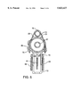
- FIG. 5 is an enlarged sectional view of the lower end of the snow making tower illustrated in FIG. 4 as seen along section line V--V, and
- FIG. 6 is an enlarged view in partial vertical section of the lower end of the snow making tower illustrated in FIG. 1 as seen along section line III--III with the tower support removed for clarity and which illustrates variations in the control valving mechanism shown in FIG. 3.
- FIG. 1 wherein there is shown a snow making tower 10 incorporating the method and apparatus of the present invention.
- This apparatus shown is one of a plurality of snow making towers 10 which are positioned along a ski slope at ground level as indicated at 11 adjacent to a ski trail as illustrated in Herman K. Dupre U.S. Pat. No. 3,706,414.
- the snow making tower 10 includes a support in the form of wood pole 12 anchored in the ground 11.
- Other support mechanisms even of the adjustable type, may be employed such as disclosed in Dupre U.S. Pat. No. 5,360,163.
- the support 12 supports elongated water conduit 13 which is fabricated of metallic thermally conducting material such as aluminum.
- Aluminum provides necessary lightness and strength to permit the tower to exceed desired heights above the ground when supported from pole 12 and is also a good heat conductor.
- Elongated hollow conduit 13 may be comprised of a single aluminum tubular extrusion or it may be comprised, as illustrated, of four pipe sections 14, 15, 16 and 17. Pipe sections 15, 16 and 17 are joined by aluminum couplings 19, and pipe sections 14 and 15 are joined together by steel coupling 20.
- coupling 20 is fabricated of steel, instead of aluminum, is that the underside of coupling 20 rests upon support bracket 21, which in turn is through bolted to pole 12 as indicated. This permits the entire elongated conduit 13 to be rotated about its vertical axis as indicated by the arrow in order to position the upper pipe section 17 with its incorporated water spray nozzles and air discharge orifices anywhere within a 360° pattern about the vertical axis of conduit 13 to compensate for varying wind conditions. Steel coupling 20 will not wear down as readily as would an aluminum coupling when bearing down on the upper surface of support bracket 21.
- Support brackets 21 and 21' in this instant merely consist each of a hinge wherein a portion of one hinge leaf is bent in the form of a loop to loosely enclose pipe section 14.
- Air under pressure is supplied to the air discharge orifices 35 at the top of tower 10 for discharging the supplied air therethrough under pressure into the ambient atmosphere in the form of jet streams 37.
- This air under pressure is supplied from a more remote source underground through pipe 56 and it may be valved off by supply valve 59.
- Water is also independently supplied under pressure through internal conduit 23, that jackets air conduit 27, to a second point of discharge above the ground or to water discharge nozzle 31 (see FIGS. 2 and 4) for discharge of water under pressure in the form of sprays 33.
- Air discharge orifices 35 and water nozzles 31 are positioned with respect to each other such that air is discharged from each air nozzle 35 is discharged in the form of a jet stream 37 which is directed into the throat of a water spray thereby forming a plume 33 of atomized water to produce snow in subfreezing conditions.
- Second water discharge nozzles 41 are provided adjacent to the first discharge nozzle and air orifice combinations 31, 35 for directing at least a portion of water discharged therefrom in the form of sprays as indicated at 44 under pressure into respective plumes 33.
- water under pressure is supplied from a remote source through underground pipe 55, which supplies water conduit 23 through flexible hose 28.
- This supply of water to conduit 23 is regulated by valve 58.
- valve 60 the supply of water from pipe 55 to outer or additional conduit 13 is regulated by valve 60 and passes to the conduit through flexible hose 61.
- the water supply to additional water nozzles 41 may be independently controlled from the supply of water to first water nozzles 31. Therefore, when the ambient subfreezing atmosphere reaches 25° or warmer, the water supply to nozzles 41 may be shut down through the use of valve 60 at the base of the tower or remotely by solenoid operation.
- flexible hose 57 is connected to air supply conduit 27 through the use of a conventional quick connect coupler 45 and in a similar fashion a flexible water hose 28 is respectively connected to conduits 23 and 13 with quick connect couplings 46 and 47.
- first water discharge nozzles 31 and air discharge orifices 35 it is preferable to use a plurality of first water discharge nozzles 31 and air discharge orifices 35 in combination and to place them about the top of the tower so that they form a plurality of respective plumes in a uniform pattern of distribution. Accordingly, the large torque arm forces applied to the upper end of tower 10 by discharge of air and water under pressure cannot damage the tower since the respective water discharge nozzle 31 and air discharge orifice 35 combinations are positioned opposite each other whereby the forces cancel each other.
- FIG. 2 four water discharge nozzle and air discharge orifice combinations 31, 35 are illustrated whereby they are positioned 90° from each other in the upper set pair and in the lower set pair to uniformly distribute the discharge therefrom to form four uniformly distributed atomized water plumes to produce snow in subfreezing ambient conditions.
- angles 32 and 34 between water nozzles 31 and conduit 23 are illustrated as 45°. Additionally, the angles between air jets 37 and water nozzles 31 is also 45°. Angle 42 of additional water nozzles 41 relative to conduit 23 is set at approximately 35°, instead of 45°, so that more of the additional water spray 44 will find its way into plumes 33 thereabove.
- angle 32 is maintained at approximately 30°, instead of 45° so that the resultant atomized plumes 33 as deflected by upper air jet streams 37 are actually deflected at an angle 32 which is something greater than 30°. This provides maximum coverage of snow fall in front of or in close to the tower while still maintaining the proper angle between jet streams 37 and upper water nozzles 31 at 45°.
- angles 34 of water nozzles 31 relative to conduit 23 might preferably be maintained at approximately 35°.
- the atomized plumes 33 in actuality maintain an angle 34 which is 45°, instead of 35°, relative to conduit 23. This provides maximum throw and spread of the plumes 33 coming from lower nozzles 31 and provides maximum snow ground coverage beyond the reach of upper nozzles 31 to thereby provide a more uniform ground coverage with the combination of the upper two sets of water nozzles 31 and air nozzles 35 in combination with the lower set of combination water nozzles 31 and air nozzles 35.
- Angles 42 of lower additional water nozzles 41 are maintained at approximately 35°, as previously mentioned, so that at least most of the water spray 44 will be directed into upper atomized plumes 33.
- the snow making tower shown in FIGS. 4 and 5 is adapted or converted to perform by externally adding on an extra or additional water conduit 13 to the tower structure with additional water nozzles 41 being provided at the upper end thereof, at the same angles and for the same purposes as water nozzles 41 shown in the embodiment of FIG. 2.
- Additional water conduit 13 is secured to first water conduit 23 and the rest of the tower 10 by means of brackets 75.
- the water supply to couplings 45 and 47 is supplied in the same fashion as shown in FIG. 1 with water supply line 28 and additional water valve 60 to selectively valve off or on the water supply to conduit 13.
- the structure and function of valve 16 will be explained in more detail hereinafter in regard to FIG. 6.
- the snow tower structure 10 illustrated in FIGS. 4 and 5 varies from the basic structure shown in FIG. 1 in that the tower 10 of FIGS. 4 and 5 is a lean-out tower which pivots or rotates not only in a horizontal plane, but also rotates about its base 74 at pivot point 73 in a vertical plane.
- Rotation in a horizontal plane is provided by support pipe 71 which is rotatably received over the upper end of ground support pipe or pole 12. Relative rotation between upper support pipe 71 and ground support pole 12 may be locked in at any desired position in a conventional manner by a set screw.
- a conventional jack screw 77 is pivotally mounted at its lower end 78 to support pipe 71 and also pivotly mounted at its upper end 79 to arm 72.
- the upper threads 81 of jack 77 are left hand threads and the lower threads 82 are right hand threads so that when the ratchet mechanism of jack 77 is operated by manipulation of handle 80, arm 72 is either raised or lowered by pivoting about pivot point 73, depending upon the ratchet drive direction selection made on jack 77.
- conduits 13, 23 and arm 72 vertically about pivot 73 are further assisted by the use of stretch counterbalance springs 84.
- FIG. 6 a variation of the control valve mechanism for the second water conduit 13 is illustrated.
- the control valve 60 is provided with an inlet 61 which is positioned in-line as illustrated in the figure with water supply conduit 28, which is supplied with water under pressure from a remote source. This creates significant water turbulence at the valve inlet 61 thereby preventing water freeze-up within the inlet and also the warmth of the turbulent water prevents valve 60 from otherwise freezing.
- Control valve 60 is secured by independent fasteners or bolts 62, via pipe flange 63, directly to supply conduit 28 whereby inlet 61 is positioned as close as possible to the supply of water under pressure within pipe 28 to prevent freeze-up of the control valve.
- This connection prevents the requirement of conventional threaded pipe connections which would add considerable length to the connection and would further remove inlet 61 of valve 60 from the water supplied under pressure within pipe 28.
- Control valve 60 is a ball valve controlled by lever 64 which turns valve ball 65 by stem 66 in order to turn the valve on and off.
- ball valve 60 is shown in its on position whereby ball valve passage 67 is aligned to provide the passage of water under pressure from pipe 28 through the valve passage on into the second water conduit 13.
- Ball valve 60 is a three-way valve so that when valve handle 64 is turned to the off position, drain passage 68 in the housing 70 of ball valve 60 will drain water directly from the inside of second or additional water conduit 13 through ball valve passage 67 and out drain passage 68. This drains all of the water from the second conduit 13 of the water tower so that water will not freeze-up within second water conduit 13.
Landscapes
- Engineering & Computer Science (AREA)
- Physics & Mathematics (AREA)
- Mechanical Engineering (AREA)
- Thermal Sciences (AREA)
- General Engineering & Computer Science (AREA)
- Nozzles (AREA)
- Buildings Adapted To Withstand Abnormal External Influences (AREA)
- Electrical Discharge Machining, Electrochemical Machining, And Combined Machining (AREA)
- Confectionery (AREA)
- Separation By Low-Temperature Treatments (AREA)
- Spray Control Apparatus (AREA)
Priority Applications (1)
| Application Number | Priority Date | Filing Date | Title |
|---|---|---|---|
| US08/875,627 US5823427A (en) | 1995-11-13 | 1996-11-12 | Method and apparatus for making snow |
Applications Claiming Priority (3)
| Application Number | Priority Date | Filing Date | Title |
|---|---|---|---|
| US654995P | 1995-11-13 | 1995-11-13 | |
| US08/875,627 US5823427A (en) | 1995-11-13 | 1996-11-12 | Method and apparatus for making snow |
| PCT/US1996/018051 WO1997018421A1 (en) | 1995-11-13 | 1996-11-12 | Method and apparatus for making snow |
Publications (1)
| Publication Number | Publication Date |
|---|---|
| US5823427A true US5823427A (en) | 1998-10-20 |
Family
ID=21721418
Family Applications (1)
| Application Number | Title | Priority Date | Filing Date |
|---|---|---|---|
| US08/875,627 Expired - Lifetime US5823427A (en) | 1995-11-13 | 1996-11-12 | Method and apparatus for making snow |
Country Status (7)
| Country | Link |
|---|---|
| US (1) | US5823427A (ja) |
| EP (1) | EP0861405B1 (ja) |
| JP (1) | JP2000500220A (ja) |
| AT (1) | ATE240498T1 (ja) |
| CA (1) | CA2237428C (ja) |
| DE (1) | DE69628185D1 (ja) |
| WO (1) | WO1997018421A1 (ja) |
Cited By (18)
| Publication number | Priority date | Publication date | Assignee | Title |
|---|---|---|---|---|
| US6032872A (en) * | 1998-05-11 | 2000-03-07 | Dupre; Herman K. | Apparatus and method for making snow |
| WO2000060291A1 (en) * | 1999-04-01 | 2000-10-12 | Dupre Herman K | Portable snow making system for home use |
| US6152380A (en) * | 2000-01-31 | 2000-11-28 | Dupre; Herman K. | Snow making tower |
| US6161769A (en) * | 1997-12-16 | 2000-12-19 | Boyne Usa, Inc. | Adjustable snow making tower |
| US6182905B1 (en) * | 2000-06-19 | 2001-02-06 | Herman K. Dupre | Apparatus and method for making snow |
| US6543699B1 (en) * | 2001-10-15 | 2003-04-08 | Herman K. Dupre | Method and apparatus for making snow |
| US6547157B2 (en) | 2000-01-06 | 2003-04-15 | Topgun Snow Making Systems, Inc. | Method and device for making snow |
| US20050189442A1 (en) * | 2004-03-01 | 2005-09-01 | Hussaini Akbar S. | Applicator head for applying fluid material to substrate |
| US20060018719A1 (en) * | 2004-07-08 | 2006-01-26 | Stern Adam M | Apparatus and method for the prevention of polar ice mass depletion |
| US20060060711A1 (en) * | 2004-09-23 | 2006-03-23 | Foianini Curt M | Spray array apparatus |
| US20060065756A1 (en) * | 2004-09-29 | 2006-03-30 | Dupre Herman K | Apparatus for making snow |
| WO2006076458A1 (en) * | 2005-01-13 | 2006-07-20 | Santry Charles N | Freeze-proof water valve for supplying secondary water to a snow making apparatus |
| US7114662B1 (en) * | 2002-12-20 | 2006-10-03 | Nikkanen John P | Snow making using low pressure air and water injection |
| US7290722B1 (en) * | 2003-12-16 | 2007-11-06 | Snow Machines, Inc. | Method and apparatus for making snow |
| EP2071258A1 (de) * | 2007-12-14 | 2009-06-17 | Bächler Top Track AG | Nukleatordüse, Verwendung einer Nukleatordüse, Schneekanone, Schneilanze und Verfahren zum Erzeugen von Eiskeimen und von künstlichem Schnee |
| US20090283607A1 (en) * | 2008-05-19 | 2009-11-19 | Santry Charles N | Snow making apparatus |
| CN106733318A (zh) * | 2015-11-19 | 2017-05-31 | 北京中联佳华科技有限公司 | 一种模块式造雪机端部雾化头 |
| MD4533B1 (ro) * | 2011-10-01 | 2017-11-30 | Okeanos Corporation | Dispozitiv hidraulic de producere a zăpezii din apă |
Families Citing this family (8)
| Publication number | Priority date | Publication date | Assignee | Title |
|---|---|---|---|---|
| FR2784905B1 (fr) | 1998-10-23 | 2001-01-12 | York Neige | Tete de pulverisation polyvalente utilisable notamment pour la fabrication de neige artificielle |
| AU6345399A (en) * | 1998-10-23 | 2000-05-15 | York Neige | Multipurpose spray head useful in particular for making artificial snow |
| JP4486360B2 (ja) | 2001-12-11 | 2010-06-23 | ニヴィス ジーエムビーエイチ エス・アール・エル | 製雪装置とその運転法 |
| KR101266069B1 (ko) * | 2011-09-19 | 2013-05-21 | 김종민 | 인공설 살포 시스템의 급수전 결빙 방지장치 |
| FR3010643A1 (fr) * | 2013-09-13 | 2015-03-20 | Snowstar | Systeme de pulverisation pour enneigeur a alimentation bi-fluide |
| CN107062727B (zh) * | 2017-03-28 | 2020-06-02 | 南京师范大学 | 一种冷冻冷藏柜性能测试装置用造雪系统 |
| FR3103030B1 (fr) | 2019-11-07 | 2022-06-17 | Technoalpin France | Dispositif de pulvérisation pour la fabrication de neige artificielle et son procédé de mise en œuvre |
| IT202100029231A1 (it) * | 2021-11-18 | 2023-05-18 | Demaclenko It S R L | Apparecchiatura per la generazione di neve |
Citations (15)
| Publication number | Priority date | Publication date | Assignee | Title |
|---|---|---|---|---|
| US3408005A (en) * | 1966-05-09 | 1968-10-29 | Willard R. Struble | Snow making nozzle |
| US3761020A (en) * | 1972-02-17 | 1973-09-25 | J Tropeano | Method and apparatus for snow making |
| US3762176A (en) * | 1969-09-18 | 1973-10-02 | B Coggins | Method and apparatus for making snow |
| US3822825A (en) * | 1973-08-08 | 1974-07-09 | H Dupre | Snow making apparatus and system |
| US3829013A (en) * | 1971-11-03 | 1974-08-13 | H Ratnik | Snow making apparatus |
| US3908903A (en) * | 1974-02-11 | 1975-09-30 | Jr Samuel L Burns | Snow making apparatus and method |
| US3923247A (en) * | 1974-07-15 | 1975-12-02 | Command Engineering Internatio | Snowmaking device |
| US3952949A (en) * | 1973-08-08 | 1976-04-27 | Dupre Herman K | Method of making snow |
| US3964682A (en) * | 1975-03-17 | 1976-06-22 | Tropeano Philip L | Method and apparatus for making snow produced by cumulative crystallization of snow particles |
| US4101073A (en) * | 1977-08-25 | 1978-07-18 | Spray Engineering Company | Two-fluid spray nozzle producing fine atomization of liquid |
| US4480788A (en) * | 1982-01-18 | 1984-11-06 | Michael Manhart | Snow gun |
| US4813597A (en) * | 1987-08-17 | 1989-03-21 | Rogers Corporation | Anti-icing snowgun |
| US4919331A (en) * | 1987-07-17 | 1990-04-24 | Mt. Holly, Inc. | Snow making apparatus and method for making snow |
| JPH02208471A (ja) * | 1989-02-06 | 1990-08-20 | Kiyoshi Tanaka | 降雪ノズル |
| US5360163A (en) * | 1993-05-17 | 1994-11-01 | Dupre Herman K | Adjustable snow making tower |
Family Cites Families (1)
| Publication number | Priority date | Publication date | Assignee | Title |
|---|---|---|---|---|
| US5004151A (en) * | 1989-11-20 | 1991-04-02 | Dupre Herman K | Method and apparatus for making snow |
-
1996
- 1996-11-12 WO PCT/US1996/018051 patent/WO1997018421A1/en active IP Right Grant
- 1996-11-12 AT AT96940365T patent/ATE240498T1/de not_active IP Right Cessation
- 1996-11-12 US US08/875,627 patent/US5823427A/en not_active Expired - Lifetime
- 1996-11-12 EP EP96940365A patent/EP0861405B1/en not_active Expired - Lifetime
- 1996-11-12 JP JP9506991A patent/JP2000500220A/ja not_active Ceased
- 1996-11-12 CA CA002237428A patent/CA2237428C/en not_active Expired - Lifetime
- 1996-11-12 DE DE69628185T patent/DE69628185D1/de not_active Expired - Lifetime
Patent Citations (15)
| Publication number | Priority date | Publication date | Assignee | Title |
|---|---|---|---|---|
| US3408005A (en) * | 1966-05-09 | 1968-10-29 | Willard R. Struble | Snow making nozzle |
| US3762176A (en) * | 1969-09-18 | 1973-10-02 | B Coggins | Method and apparatus for making snow |
| US3829013A (en) * | 1971-11-03 | 1974-08-13 | H Ratnik | Snow making apparatus |
| US3761020A (en) * | 1972-02-17 | 1973-09-25 | J Tropeano | Method and apparatus for snow making |
| US3952949A (en) * | 1973-08-08 | 1976-04-27 | Dupre Herman K | Method of making snow |
| US3822825A (en) * | 1973-08-08 | 1974-07-09 | H Dupre | Snow making apparatus and system |
| US3908903A (en) * | 1974-02-11 | 1975-09-30 | Jr Samuel L Burns | Snow making apparatus and method |
| US3923247A (en) * | 1974-07-15 | 1975-12-02 | Command Engineering Internatio | Snowmaking device |
| US3964682A (en) * | 1975-03-17 | 1976-06-22 | Tropeano Philip L | Method and apparatus for making snow produced by cumulative crystallization of snow particles |
| US4101073A (en) * | 1977-08-25 | 1978-07-18 | Spray Engineering Company | Two-fluid spray nozzle producing fine atomization of liquid |
| US4480788A (en) * | 1982-01-18 | 1984-11-06 | Michael Manhart | Snow gun |
| US4919331A (en) * | 1987-07-17 | 1990-04-24 | Mt. Holly, Inc. | Snow making apparatus and method for making snow |
| US4813597A (en) * | 1987-08-17 | 1989-03-21 | Rogers Corporation | Anti-icing snowgun |
| JPH02208471A (ja) * | 1989-02-06 | 1990-08-20 | Kiyoshi Tanaka | 降雪ノズル |
| US5360163A (en) * | 1993-05-17 | 1994-11-01 | Dupre Herman K | Adjustable snow making tower |
Cited By (27)
| Publication number | Priority date | Publication date | Assignee | Title |
|---|---|---|---|---|
| US6161769A (en) * | 1997-12-16 | 2000-12-19 | Boyne Usa, Inc. | Adjustable snow making tower |
| US6032872A (en) * | 1998-05-11 | 2000-03-07 | Dupre; Herman K. | Apparatus and method for making snow |
| WO2000060291A1 (en) * | 1999-04-01 | 2000-10-12 | Dupre Herman K | Portable snow making system for home use |
| US6547157B2 (en) | 2000-01-06 | 2003-04-15 | Topgun Snow Making Systems, Inc. | Method and device for making snow |
| US6152380A (en) * | 2000-01-31 | 2000-11-28 | Dupre; Herman K. | Snow making tower |
| US6182905B1 (en) * | 2000-06-19 | 2001-02-06 | Herman K. Dupre | Apparatus and method for making snow |
| US6543699B1 (en) * | 2001-10-15 | 2003-04-08 | Herman K. Dupre | Method and apparatus for making snow |
| US7114662B1 (en) * | 2002-12-20 | 2006-10-03 | Nikkanen John P | Snow making using low pressure air and water injection |
| US7290722B1 (en) * | 2003-12-16 | 2007-11-06 | Snow Machines, Inc. | Method and apparatus for making snow |
| US20050189442A1 (en) * | 2004-03-01 | 2005-09-01 | Hussaini Akbar S. | Applicator head for applying fluid material to substrate |
| US7253218B2 (en) | 2004-03-01 | 2007-08-07 | H.B. Fuller Company | Sound damping compositions and methods for applying and baking same onto substrates |
| US20060018719A1 (en) * | 2004-07-08 | 2006-01-26 | Stern Adam M | Apparatus and method for the prevention of polar ice mass depletion |
| US7225999B2 (en) * | 2004-09-23 | 2007-06-05 | The United States Of America As Represented By The Secretary Of The Navy | Spray array apparatus |
| US20060060711A1 (en) * | 2004-09-23 | 2006-03-23 | Foianini Curt M | Spray array apparatus |
| US20060065756A1 (en) * | 2004-09-29 | 2006-03-30 | Dupre Herman K | Apparatus for making snow |
| WO2006076458A1 (en) * | 2005-01-13 | 2006-07-20 | Santry Charles N | Freeze-proof water valve for supplying secondary water to a snow making apparatus |
| US20070152079A1 (en) * | 2005-01-13 | 2007-07-05 | Santry Charles N | Freeze-proof water valve for supplying secondary water to snow making apparatus |
| US7311266B2 (en) * | 2005-01-13 | 2007-12-25 | Santry Charles N | Freeze-proof water valve for supplying secondary water to snow making apparatus |
| US10527336B2 (en) | 2007-12-14 | 2020-01-07 | Baechler Top Track Ag | Arrangement, use of an arrangement, device, snow lance and method for producing ice nuclei and artificial snow |
| WO2009077211A1 (de) * | 2007-12-14 | 2009-06-25 | Bächler Top Track Ag | Anordnung, verwendung einer anordnung, vorrichtung, schneilanze und verfahren zum erzeugen von eiskeimen und von künstlichem schnee |
| EP2071258A1 (de) * | 2007-12-14 | 2009-06-17 | Bächler Top Track AG | Nukleatordüse, Verwendung einer Nukleatordüse, Schneekanone, Schneilanze und Verfahren zum Erzeugen von Eiskeimen und von künstlichem Schnee |
| US20110049258A1 (en) * | 2007-12-14 | 2011-03-03 | Baechler Top Track Ag | Arrangement, Use of an Arrangement, Device, Snow Lance and Method for Producing Ice Nuclei and Artificial Snow |
| US9470449B2 (en) * | 2007-12-14 | 2016-10-18 | Baechler Top Track Ag | Arrangement, use of an arrangement, device, snow lance and method for producing ice nuclei and artificial snow |
| US20090283607A1 (en) * | 2008-05-19 | 2009-11-19 | Santry Charles N | Snow making apparatus |
| US7874500B2 (en) * | 2008-05-19 | 2011-01-25 | Santry Charles N | Snow making apparatus |
| MD4533B1 (ro) * | 2011-10-01 | 2017-11-30 | Okeanos Corporation | Dispozitiv hidraulic de producere a zăpezii din apă |
| CN106733318A (zh) * | 2015-11-19 | 2017-05-31 | 北京中联佳华科技有限公司 | 一种模块式造雪机端部雾化头 |
Also Published As
| Publication number | Publication date |
|---|---|
| EP0861405B1 (en) | 2003-05-14 |
| CA2237428C (en) | 2003-03-18 |
| EP0861405A4 (ja) | 1998-10-14 |
| ATE240498T1 (de) | 2003-05-15 |
| DE69628185D1 (de) | 2003-06-18 |
| JP2000500220A (ja) | 2000-01-11 |
| WO1997018421A1 (en) | 1997-05-22 |
| CA2237428A1 (en) | 1997-05-22 |
| EP0861405A1 (en) | 1998-09-02 |
Similar Documents
| Publication | Publication Date | Title |
|---|---|---|
| US5823427A (en) | Method and apparatus for making snow | |
| US5004151A (en) | Method and apparatus for making snow | |
| US3952949A (en) | Method of making snow | |
| CA2146013C (en) | Machine for making artificial snow and method | |
| US3706414A (en) | Apparatus for making snow | |
| US3964682A (en) | Method and apparatus for making snow produced by cumulative crystallization of snow particles | |
| EP2526355B1 (en) | Snow making apparatus and method | |
| US6119956A (en) | Snow gun for making artificial snow | |
| EP1613435B1 (en) | Nozzles | |
| US6152380A (en) | Snow making tower | |
| US5890654A (en) | Snow making tower | |
| US6547157B2 (en) | Method and device for making snow | |
| US5593090A (en) | Snow gun | |
| US20070152079A1 (en) | Freeze-proof water valve for supplying secondary water to snow making apparatus | |
| US5890652A (en) | Self-regulating snowmaking nozzle, system and method | |
| CN112774888A (zh) | 用于制造人造雪的喷射设备及其使用方法 | |
| WO1995033962A1 (en) | Compressed air hydrant heater device | |
| CA2276016C (en) | Snow gun for making artificial snow | |
| JPH09210526A (ja) | 人工雪の製造装置及び方法 | |
| KR20040040776A (ko) | 인공설의 제조장치 | |
| JPH07239164A (ja) | 氷散布設備用散水装置 | |
| AU2004226877B2 (en) | Nozzles | |
| AU2024200564A1 (en) | Remote Multi Functional snow making machine | |
| KR200303621Y1 (ko) | 인공설의 제조장치 | |
| US20120074242A1 (en) | Axial rotatable snow making spray head and method for making snow |
Legal Events
| Date | Code | Title | Description |
|---|---|---|---|
| AS | Assignment |
Owner name: SNOW ECONOMICS, INC., MASSACHUSETTS Free format text: ASSIGNMENT OF ASSIGNORS INTEREST;ASSIGNORS:DUPRE, HERMAN K.;SANTRY, CHARLES N.;REEL/FRAME:008827/0361;SIGNING DATES FROM 19970522 TO 19970617 |
|
| STCF | Information on status: patent grant |
Free format text: PATENTED CASE |
|
| FEPP | Fee payment procedure |
Free format text: PAYOR NUMBER ASSIGNED (ORIGINAL EVENT CODE: ASPN); ENTITY STATUS OF PATENT OWNER: SMALL ENTITY |
|
| FEPP | Fee payment procedure |
Free format text: PAT HOLDER CLAIMS SMALL ENTITY STATUS, ENTITY STATUS SET TO SMALL (ORIGINAL EVENT CODE: LTOS); ENTITY STATUS OF PATENT OWNER: SMALL ENTITY |
|
| FPAY | Fee payment |
Year of fee payment: 4 |
|
| FPAY | Fee payment |
Year of fee payment: 8 |
|
| FPAY | Fee payment |
Year of fee payment: 12 |