US5790966A - Method for determining steering position of automotive steering mechanism - Google Patents
Method for determining steering position of automotive steering mechanism Download PDFInfo
- Publication number
- US5790966A US5790966A US08/625,966 US62596696A US5790966A US 5790966 A US5790966 A US 5790966A US 62596696 A US62596696 A US 62596696A US 5790966 A US5790966 A US 5790966A
- Authority
- US
- United States
- Prior art keywords
- signal
- steering
- center position
- steering wheel
- wheel angle
- Prior art date
- Legal status (The legal status is an assumption and is not a legal conclusion. Google has not performed a legal analysis and makes no representation as to the accuracy of the status listed.)
- Expired - Lifetime
Links
Images


Classifications
-
- B—PERFORMING OPERATIONS; TRANSPORTING
- B60—VEHICLES IN GENERAL
- B60G—VEHICLE SUSPENSION ARRANGEMENTS
- B60G17/00—Resilient suspensions having means for adjusting the spring or vibration-damper characteristics, for regulating the distance between a supporting surface and a sprung part of vehicle or for locking suspension during use to meet varying vehicular or surface conditions, e.g. due to speed or load
- B60G17/015—Resilient suspensions having means for adjusting the spring or vibration-damper characteristics, for regulating the distance between a supporting surface and a sprung part of vehicle or for locking suspension during use to meet varying vehicular or surface conditions, e.g. due to speed or load the regulating means comprising electric or electronic elements
- B60G17/0195—Resilient suspensions having means for adjusting the spring or vibration-damper characteristics, for regulating the distance between a supporting surface and a sprung part of vehicle or for locking suspension during use to meet varying vehicular or surface conditions, e.g. due to speed or load the regulating means comprising electric or electronic elements characterised by the regulation being combined with other vehicle control systems
-
- B—PERFORMING OPERATIONS; TRANSPORTING
- B60—VEHICLES IN GENERAL
- B60G—VEHICLE SUSPENSION ARRANGEMENTS
- B60G17/00—Resilient suspensions having means for adjusting the spring or vibration-damper characteristics, for regulating the distance between a supporting surface and a sprung part of vehicle or for locking suspension during use to meet varying vehicular or surface conditions, e.g. due to speed or load
- B60G17/015—Resilient suspensions having means for adjusting the spring or vibration-damper characteristics, for regulating the distance between a supporting surface and a sprung part of vehicle or for locking suspension during use to meet varying vehicular or surface conditions, e.g. due to speed or load the regulating means comprising electric or electronic elements
- B60G17/016—Resilient suspensions having means for adjusting the spring or vibration-damper characteristics, for regulating the distance between a supporting surface and a sprung part of vehicle or for locking suspension during use to meet varying vehicular or surface conditions, e.g. due to speed or load the regulating means comprising electric or electronic elements characterised by their responsiveness, when the vehicle is travelling, to specific motion, a specific condition, or driver input
- B60G17/0162—Resilient suspensions having means for adjusting the spring or vibration-damper characteristics, for regulating the distance between a supporting surface and a sprung part of vehicle or for locking suspension during use to meet varying vehicular or surface conditions, e.g. due to speed or load the regulating means comprising electric or electronic elements characterised by their responsiveness, when the vehicle is travelling, to specific motion, a specific condition, or driver input mainly during a motion involving steering operation, e.g. cornering, overtaking
-
- B—PERFORMING OPERATIONS; TRANSPORTING
- B60—VEHICLES IN GENERAL
- B60G—VEHICLE SUSPENSION ARRANGEMENTS
- B60G17/00—Resilient suspensions having means for adjusting the spring or vibration-damper characteristics, for regulating the distance between a supporting surface and a sprung part of vehicle or for locking suspension during use to meet varying vehicular or surface conditions, e.g. due to speed or load
- B60G17/015—Resilient suspensions having means for adjusting the spring or vibration-damper characteristics, for regulating the distance between a supporting surface and a sprung part of vehicle or for locking suspension during use to meet varying vehicular or surface conditions, e.g. due to speed or load the regulating means comprising electric or electronic elements
- B60G17/019—Resilient suspensions having means for adjusting the spring or vibration-damper characteristics, for regulating the distance between a supporting surface and a sprung part of vehicle or for locking suspension during use to meet varying vehicular or surface conditions, e.g. due to speed or load the regulating means comprising electric or electronic elements characterised by the type of sensor or the arrangement thereof
-
- B—PERFORMING OPERATIONS; TRANSPORTING
- B62—LAND VEHICLES FOR TRAVELLING OTHERWISE THAN ON RAILS
- B62D—MOTOR VEHICLES; TRAILERS
- B62D15/00—Steering not otherwise provided for
- B62D15/02—Steering position indicators ; Steering position determination; Steering aids
-
- B—PERFORMING OPERATIONS; TRANSPORTING
- B60—VEHICLES IN GENERAL
- B60G—VEHICLE SUSPENSION ARRANGEMENTS
- B60G2400/00—Indexing codes relating to detected, measured or calculated conditions or factors
- B60G2400/20—Speed
- B60G2400/204—Vehicle speed
-
- B—PERFORMING OPERATIONS; TRANSPORTING
- B60—VEHICLES IN GENERAL
- B60G—VEHICLE SUSPENSION ARRANGEMENTS
- B60G2400/00—Indexing codes relating to detected, measured or calculated conditions or factors
- B60G2400/40—Steering conditions
- B60G2400/41—Steering angle
-
- B—PERFORMING OPERATIONS; TRANSPORTING
- B60—VEHICLES IN GENERAL
- B60G—VEHICLE SUSPENSION ARRANGEMENTS
- B60G2400/00—Indexing codes relating to detected, measured or calculated conditions or factors
- B60G2400/40—Steering conditions
- B60G2400/41—Steering angle
- B60G2400/412—Steering angle of steering wheel or column
-
- B—PERFORMING OPERATIONS; TRANSPORTING
- B60—VEHICLES IN GENERAL
- B60G—VEHICLE SUSPENSION ARRANGEMENTS
- B60G2401/00—Indexing codes relating to the type of sensors based on the principle of their operation
-
- B—PERFORMING OPERATIONS; TRANSPORTING
- B60—VEHICLES IN GENERAL
- B60G—VEHICLE SUSPENSION ARRANGEMENTS
- B60G2600/00—Indexing codes relating to particular elements, systems or processes used on suspension systems or suspension control systems
- B60G2600/18—Automatic control means
- B60G2600/187—Digital Controller Details and Signal Treatment
-
- B—PERFORMING OPERATIONS; TRANSPORTING
- B60—VEHICLES IN GENERAL
- B60G—VEHICLE SUSPENSION ARRANGEMENTS
- B60G2600/00—Indexing codes relating to particular elements, systems or processes used on suspension systems or suspension control systems
- B60G2600/70—Computer memory; Data storage, e.g. maps for adaptive control
-
- B—PERFORMING OPERATIONS; TRANSPORTING
- B60—VEHICLES IN GENERAL
- B60G—VEHICLE SUSPENSION ARRANGEMENTS
- B60G2800/00—Indexing codes relating to the type of movement or to the condition of the vehicle and to the end result to be achieved by the control action
- B60G2800/01—Attitude or posture control
- B60G2800/012—Rolling condition
-
- B—PERFORMING OPERATIONS; TRANSPORTING
- B60—VEHICLES IN GENERAL
- B60G—VEHICLE SUSPENSION ARRANGEMENTS
- B60G2800/00—Indexing codes relating to the type of movement or to the condition of the vehicle and to the end result to be achieved by the control action
- B60G2800/24—Steering, cornering
-
- B—PERFORMING OPERATIONS; TRANSPORTING
- B60—VEHICLES IN GENERAL
- B60G—VEHICLE SUSPENSION ARRANGEMENTS
- B60G2800/00—Indexing codes relating to the type of movement or to the condition of the vehicle and to the end result to be achieved by the control action
- B60G2800/24—Steering, cornering
- B60G2800/246—Understeer
-
- B—PERFORMING OPERATIONS; TRANSPORTING
- B60—VEHICLES IN GENERAL
- B60G—VEHICLE SUSPENSION ARRANGEMENTS
- B60G2800/00—Indexing codes relating to the type of movement or to the condition of the vehicle and to the end result to be achieved by the control action
- B60G2800/24—Steering, cornering
- B60G2800/248—Neutral steering behaviour
-
- B—PERFORMING OPERATIONS; TRANSPORTING
- B60—VEHICLES IN GENERAL
- B60G—VEHICLE SUSPENSION ARRANGEMENTS
- B60G2800/00—Indexing codes relating to the type of movement or to the condition of the vehicle and to the end result to be achieved by the control action
- B60G2800/70—Estimating or calculating vehicle parameters or state variables
- B60G2800/702—Improving accuracy of a sensor signal
-
- B—PERFORMING OPERATIONS; TRANSPORTING
- B60—VEHICLES IN GENERAL
- B60G—VEHICLE SUSPENSION ARRANGEMENTS
- B60G2800/00—Indexing codes relating to the type of movement or to the condition of the vehicle and to the end result to be achieved by the control action
- B60G2800/90—System Controller type
- B60G2800/91—Suspension Control
- B60G2800/912—Attitude Control; levelling control
- B60G2800/9122—ARS - Anti-Roll System Control
-
- B—PERFORMING OPERATIONS; TRANSPORTING
- B60—VEHICLES IN GENERAL
- B60G—VEHICLE SUSPENSION ARRANGEMENTS
- B60G2800/00—Indexing codes relating to the type of movement or to the condition of the vehicle and to the end result to be achieved by the control action
- B60G2800/90—System Controller type
- B60G2800/91—Suspension Control
- B60G2800/914—Height Control System
-
- B—PERFORMING OPERATIONS; TRANSPORTING
- B60—VEHICLES IN GENERAL
- B60G—VEHICLE SUSPENSION ARRANGEMENTS
- B60G2800/00—Indexing codes relating to the type of movement or to the condition of the vehicle and to the end result to be achieved by the control action
- B60G2800/90—System Controller type
- B60G2800/92—ABS - Brake Control
-
- B—PERFORMING OPERATIONS; TRANSPORTING
- B60—VEHICLES IN GENERAL
- B60G—VEHICLE SUSPENSION ARRANGEMENTS
- B60G2800/00—Indexing codes relating to the type of movement or to the condition of the vehicle and to the end result to be achieved by the control action
- B60G2800/90—System Controller type
- B60G2800/96—ASC - Assisted or power Steering control
Definitions
- This invention relates to an apparatus for determining the steering position of a vehicular steering mechanism. This method is useful for controlling a vehicular braking system and other automotive devices.
- steering angle sensors to provide steering input for the control of suspension units.
- Systems employing fixed steering angle sensors are prone to failure due to calibration of the sensor.
- sensors are unable to compensate for steering system changes, such as wheel misalignment, road crown and cross wind compensation in addition to wear within the steering mechanism.
- the steering sensor system disclosed in U.S. Pat. No. 4,848,791 which is assigned to the assignee of the present invention, utilizes a software program in which steering center position is statistically determined over a fixed period of time sufficient to insure an accurate center position. While this system eliminates the calibration problems associated with fixed sensors, the system described requires significant time during initial operation to converge on a center position, thereby reducing the accuracy of the calculated instantaneous steering position.
- a method for determining the steering position of an automotive steering mechanism to be used for controlling an automotive device comprises the following steps:
- FIG. 1 is a perspective drawing of a motor vehicle including a system according to the present invention. This figure shows various components of a system embodying the present invention.
- FIG. 2 is a plan view, partially cut away, of a steering sensor comprising a component part of a system according to the present invention.
- FIG. 3 is a cross sectional view of the steering sensor of the present invention taken along the line 3--3 of FIG. 2.
- FIG. 4 is an overall system block diagram in accordance with an embodiment of this invention.
- FIG. 5A illustrates the output waveforms of the detectors employed in the steering sensor illustrated in FIGS. 2 and 3 for clockwise rotation.
- FIG. 5B illustrates the output waveforms of the detectors employed in the steering sensor illustrated in FIGS. 2 and 3 for counterclockwise rotation.
- FIG. 6 is a truth table illustrating the outputs of detectors A and B shown in FIGS. 2-3 as the steering sensor of the present invention is rotated counterclockwise and clockwise.
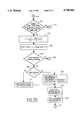
- FIGS. 7A, 7B and 7C are logic flow block diagrams in accordance with the principles of the present invention.
- FIG. 8 shows a time based plot of some variables generated during the execution of algorithms in accordance with the principles of the present invention.
- a method according to the present invention is intended for use with electronically controlled hydraulic braking systems and also steering gears typically found in automotive vehicles.
- the motor vehicle shown in FIG. 1 is equipped with electronically controlled hydraulic braking systems having controlled brake actuators 12 which cooperate with wheel and tire assemblies 10.
- These brake actuators may be constructed in a known manner such as that commonly employed on Ford Motor vehicles in use today.
- a method according to the present invention could be utilized in the control of other adjustable vehicular devices such as adjustable suspension units, hydraulic crossover suspension systems, variable volume air suspension springs, or variable stabilizer bars.
- system according to the present invention could be employed with semi-active and active suspension devices.
- control module 14 receives inputs from steering sensor 20, speed sensor 16, yaw sensor 17 and brake sensor 18.
- speed sensor 16 speed sensor 16
- yaw sensor 17 speed sensor 16
- brake sensor 18 brake sensor 18.
- height sensors and accelerometers could be employed with a suspension control system utilizing the present invention.
- a system according to the present invention could, as previously noted, be used with braking systems or other automotive equipment with which it is necessary to know the position of the steering mechanism.
- speed sensor 16 could comprise any of a variety of devices or systems employed in automotive vehicles.
- One type of automotive speed sensor suitable for use with a system according to the present invention comprises a speed module for receiving input from multiple speed sensors adapted to indicate the speed of the individual wheels.
- the speed module derives a longitudinal vehicle speed signal by combining the signals from the speed sensors.
- One such type of speed signal module is embodied in brake control modules presently used in Ford Motor Company vehicles.
- the individual wheel speeds are ascertained using pulse generators disposed at each wheel.
- a control module may output commands to brake actuators 12 (controlled devices 12, FIG. 4).
- the processor within the control module and its associated peripheral equipment could be structured according to several different architectures. In a preferred embodiment, however, the processor is configured so that a control program is sequentially read for each unit command from a read-only memory (ROM) 26 which stores preset control programs. Unit commands are executed by a central processing unit (CPU) 28.
- the processor integrally includes an input-output control circuit (I/O) 30 for exchanging data with external devices and a random access memory (RAM) 32 for temporarily holding data while the data are being processed.
- I/O input-output control circuit
- RAM random access memory
- Steering sensor 20, acting in conjunction with control module 14, includes means for measuring the excursion angle of the steering mechanism as a series of marker counts or steps measured from the initial position which the steering mechanism occupied when the system was activated by an operator keying on the ignition of the vehicle.
- steering sensor 20 comprises shutter wheel 36 attached to steering shaft 38, which shaft rotates in unison with the steering wheel as the steering wheel is turned by the driver of the vehicle.
- Shutter wheel 36 has a plurality of apertures 40, in this case 48 in number, which apertures serve to trigger the activity of spaced apart detectors A and B as the shutter wheel is rotated with the steering system of the vehicle. Detectors A and B detect movement of the shutter wheel. Because there are 48 apertures contained within shutter wheel 36, the steering sensor provides a signal 192 times during one revolution of the steering wheel and as a result each of the 192 counts or steps indicates 1.875 degrees of rotation of the steering mechanism.
- each of detectors A and B includes a light emitting diode (LED) 42 and a photo diode 44.
- the combination of the LED and photo diode is used to detect movement of shutter wheel 36 and, hence, the steering mechanism.
- the photo diodes have two states; i.e., they are bi-stable.
- a conducting state occurs whenever light from the paired LED passes through an aperture 40 in the shutter wheel and impinges upon the photo diode.
- the output of the detector circuit then rises to approximately 10 volts.
- a nonconducting state exists whenever the shutter wheel blocks the transmission of light between the LED and the photo diode.
- clockwise rotation of shutter wheel 36 produces a waveform pattern for the detectors in which detector A undergoes its transition prior to detector B. In other words, detector A leads detector B.
- counterclockwise rotation of the steering sensor produces a waveform pattern for the detectors in which detector A undergoes its transition after detector B and detector A thus lags detector B.
- the outputs of detectors A and B are fed into the control module, and in this manner the control module is allowed to track the direction of the steering mechanism's movement.
- Increasing the number of apertures on shutter wheel 36 improves the resolution of the sensor.
- the present invention allows a significant increase in the number of apertures while maintaining the ability to reject meaningless steering wheel excursions (by determining a finer resolution).
- FIG. 6 is a tabulation of the waveforms shown in FIGS. 5A and 5B in a digital format.
- the approximately 10 volts maximum output of the detectors is treated as a logical "1", while the zero output state is treated as a logical "0".
- FIG. 6 shows each of the possible logic pair states which could be output by detectors A and B. The pairs are arranged in the order in which they will be received by the control module for both counterclockwise and clockwise rotation. As seen in FIG. 6, counterclockwise rotation is read from the bottom of the figure to the upper part of the figure with clockwise rotation being read from the top of the tabulation to the lower part of the tabulation.
- detector devices A and B generate a cyclical series of two-bit, binary coded data (SWA), corresponding to a finite amount of rotation of steering shaft 38 relative to the initial position of the steering mechanism at startup.
- SWACENTER binary coded data
- SWAEST a corresponding estimate of the actual steering angle
- the present invention provides an improvement in determining the estimated center position necessary for calculating the steering position from the raw steering data (SWA) obtained from the steering sensor 20.
- SWA raw steering data
- the present invention determines the location of the center position according to one of three techniques, an initial center algorithm, an interim center algorithm and a final center algorithm.
- the primary difference among the algorithms is the speed with which they converge on a center position estimate and the accuracy or reliability of this center position estimate.
- the initial center algorithm is used to provide a very rapid estimate of the center position.
- the processor switches over and uses the interim center algorithm.
- the processor makes this switch when it senses the steering mechanism is substantially positioned in the estimated center position. Once the switch has been made, the processor will not return to the initial center algorithm until the ignition is switched from off to on.
- the processor will refine the estimate of the center position using the interim center algorithm until further operating characteristics are satisfied. When these characteristics are satisfied, the processor switches to the final center algorithm for providing the final adjustments to the center position estimate. Similarly, the processor will not exit the final center algorithm until the ignition is switched off. The operation of these three center position estimating algorithms and how they are integrated into a system will be described below.
- the processor starts the illustrated algorithm when the operator keys on the vehicle ignition.
- the processor then moves to block 102 where the various sensors are read and their data input to the processor. If this is the first time through the algorithm all of the variables are initialized with predetermined values.
- the processor then steps to block 104 where maximum yaw velocity and acceleration limits (MaxYawV, MaxYawAcc) are set depending on the vehicle longitudinal speed read at block 102.
- the processor then proceeds to block 106 and calculates the yaw acceleration (YawAcc) and other variables from the yaw rate data read at block 102.
- the processor then advances to block 108.
- the processor updates minimum and maximum steering wheel angles (SWAMIN, SWAMAX) experienced thus far by comparing their present values with the present steering wheel angle data (SWA).
- SWAMIN minimum and maximum steering wheel angles
- SWAMAX present steering wheel angle data
- the processor then advances to block 110 and calculates a quantitative straight path indicator (SWAPOC) of the likelihood that the vehicle is traveling in a straight line.
- SWAPOC ranges from 0 to 100, with 100 indicating a strong likelihood that the vehicle is traveling straight.
- SWAPOC is calculated according to one of two formulas. First, the operating characteristics of the motor vehicle are assessed to determine which of two formulas to use to update SWAPOC.
- a first formula will be used. If these conditions are satisfied, the processor uses the first relationship to increase the value for SWAPOC, indicating that the vehicle is likely operating in a straight path. The assumption is that if the vehicle operates under these conditions long enough, then the vehicle is traveling straight. If, on the other hand, these conditions are not satisfied, then the processor uses a second relationship to decrease SWAPOC.
- the first relationship takes the following form:
- the processor ascertains whether or not the final center routine has been started by checking the status of a flag, FOUNDCENTER. At the outset, the FOUNDCENTER flag will be false, or 0, and the processor will proceed to conditional block 114. At conditional block 114 the processor evaluates the indicator SWAPOC to determine whether or not SWAPOC has attained a value greater than 95. Similarly, at the outset SWAPOC will be less than 95 and the processor will proceed through advance block 115 to block 116.
- the processor evaluates several vehicle conditions at the conditional block 116 to determine whether or not the vehicle is operating in a state for which a center position should be estimated.
- this conditional block is satisfied by the existence of the following conditions: the ignition has been switched on long enough for the yaw sensor to power-up and stabilize; the vehicle is traveling at less than a predetermined minimum, which in the present invention is 7 kph; and the IVD system is inactive. If any one of these conditions is not satisfied the processor forgoes updating the center position and proceeds via advance block 119 to block 118.
- the processor uses the existing estimate of SWACENTER to determine the estimate of the steering angle, SWAEST according to the following relationship:
- SWA is the uncentered signal generated by the steering wheel angle sensor.
- SWAEST would assume a value equal to SWA since SWACENTER would still have its initialized value of 0.
- the processor then proceeds to block 122 where the present value of the yaw rate signal, YawVRaw, is stored in memory as YawVRawZ1 for use in first order filtering devices.
- the processor then proceeds to block 102 via advance block 123.
- the sensors are read and the variables are updated based on the new data.
- the processor proceeds through blocks 104, 106, 108 and 110 as previously described.
- conditional block 112 assume FOUNDCENTER remains "false” and the processor proceeds to block 114. Also assume that SWAPOC has not yet exceeded a value of 95.
- the processor proceeds via advance block 115 to conditional block 116, where the processor will once again assess the operating characteristics of the vehicle. Assume this time the characteristics described above are satisfied and the processor proceeds to block 124.
- r the yaw rate of the vehicle
- the processor can compute a yaw measurement based steering wheel angle, SWAFromYAW.
- the processor calculates SWAFromYAW according to the following relationship:
- KSteer2SWA steering ratio, a constant dependent on the steering mechanism and steering geometry.
- the processor determines whether the absolute value of SWAFromYAW is less than a predetermined limit, SWAFromYAWlimit.
- This predetermined limit represents boundaries within which a steering angle would be considered to represent straight line travel. For instance, the predetermined limit could be set to 5 degrees. If the absolute value of SWAFromYAW is less than 5 degrees, then the processor will assume the vehicle is going straight or transitioning through the straight line steer position. The first time this occurs is referred to an "initial crossing". A crossing refers to the crossing from a non-zero steering position into a boundary representative of substantially straight ahead driving, or zero steering angle. The crossing may also be referred to as a zero crossing. Assuming that the absolute value SWAFromYAW is greater than SWAFromYAWlimit, the processor proceeds to block 132 via advance block 129.
- the processor sets the initial center flag, INITIALCENTER, equal to "true” or "1" at block 132 to indicate that the processor has started the initial center algorithm.
- the initial center algorithm first determines if the present steering event is greater than a predetermined minimum. It has been observed that SWACENTER values calculated when steering wheel angles are less than 180 degrees are more accurate than values calculated when the steering wheel angles are greater than 180 degrees. Therefore, it is advantageous to use data taken during steering events having steering wheel angles less than 180 degrees. The present embodiment of the initial center algorithm benefits from this observation.
- conditional block 134 the processor evaluates the steering angle calculated from the yaw data, SWAFromYAW to determine whether it is less than 180 degrees. Assuming SWAFromYAW is not less than 180 degrees, the processor proceeds to conditional block 135. There, the processor checks a counter, FSETTLE180, to determine whether the processor has calculated SWACENTER using SWAFromYAW data of less than 180 degrees. If FSETTLE180 is greater than zero, the processor skips to block 118 via advance block 119 where SWAEST is updated using the existing SWACENTER value. This prevents the processor from recalculating SWACENTER if it has been calculated using SWAFromYAW data of less than 180 degrees. If FSETTLE180 is equal to 0, then the processor continues to conditional block 137.
- the processor determines whether SWAFromYAW is less than 360 degrees. This is necessary because it has been determined in practice that for very large steering angles, a more accurate SWACENTER can be obtained if a unique value is used for the steering ratio, KSteer2SWA. Assuming SWAFromYAW is not less than 360 degrees, the processor will proceed to conditional block 143. There, the processor checks another counter, FSETTLE500, which counts the number of times the initial center algorithm calculates SWACENTER when SWAFromYAW is greater than or equal to 180 degrees, but less than 360 degrees. Here, SWACENTER will only be calculated if FSETTLE500 is equal to zero, indicating that SWACENTER has not been calculated using data less than 360 degrees.
- SWADynamic represents the SWA signal from the steering angle sensor after it has been passed through a second order filter.
- SWACENTER is filtered by a first order filter and SWACENTERold is set to equal the new filtered SWACENTER.
- the processor proceeds to block 118 via advance block 119. The processor then proceeds to calculate SWAEST and return back through the loop to ultimately end up in the initial center routine again, assuming that SWAPOC had not exceeded 95 or SWAFromYAW had not fallen below SWAFromYAWlimit.
- conditional block 139 if FSETTLE500 is greater than 300 the processor would proceed to block 118 via advance block 119, indicating that no additional calculations need be made using this range of data. If FSETTLE500 is less than 300, the processor proceeds to block 138, where FSETTLE500 is incremented and SWACENTER is calculated according to the following relationship:
- the processor filters the SWACENTER signal through a first order filter and updates SWACENTERold with the new SWACENTER value.
- the processor then proceeds to block 118 via advance block 119 where SWAEST is updated using the new SWACENTER value. Assuming that SWAPOC had not exceeded 95 or SWAFromYAW had not fallen below SWAFromYAWlimit, the processor returns to the initial center algorithm.
- SWAFromYAW is less than 180 degrees.
- the processor proceeds to conditional block 150 to evaluate FSETTLE180, to determine if it is below a predetermined limit.
- This counter serves two purposes. First, once the initial center algorithm makes its first center position estimate using data acquired with SWAFromYAW less than 180 degrees, the processor increments the counter and the routine will not recalculate SWACENTER when SWAFromYAW is greater than or equal to 180 degrees. The second purpose eliminates redundant computation. It has been observed that the SWACENTER does not improve after a predetermined number of calculations, that is to say it converges within the limits of accuracy of the initial center algorithm. In the presently preferred embodiment, this corresponds to 300 iterations.
- FSETTLE180 is greater than 300, the processor proceeds directly to block 118 via advance block 119 preventing any further updating of SWACENTER by the initial center algorithm. If FSETTLE180 is less than 300, the processor proceeds to block 151, where FSETTLE180 is incremented and SWACENTER is calculated according to the following relationship:
- the processor filters SWACENTER signal through a first order filter and updates SWACENTERold with the new SWACENTER value.
- the processor then proceeds to block 118 via advance block 119 where SWAEST is updated using the new SWACENTER value.
- the processor will continue in the initial center algorithm until SWAPOC becomes greater than 95 or the SWAFromYAW becomes less than the SWAFromYAWlimit at block 128.
- the interim center algorithm is initially entered at block 154 when the absolute value of SWAFromYAW becomes less than the SWAFromYAWlimit as tested at conditional block 128.
- additional criteria may be used to determine the stability of the zero crossing. For instance, it may be advantageous to determine the frequency of zero crossings. If the frequency exceeds a threshold, the zero crossing data may be rejected. If these conditions are satisfied, then this corresponds to the initial center crossing.
- the processor checks a flag, FIRSTSWADYN, to determine if this is the initial center crossing.
- FIRSTSWADYN is "true” or "1”
- this pass represents the initial center crossing and the processor proceeds to block 156.
- the processor sets the flag, FIRSTSWADYN, to "false” or "0", indicating that subsequent center crossings will not be the initial center crossing.
- the processor also sets another flag, INTERIMCENTER, to "1" to indicate that the interim center algorithm has been entered, which will prevent the processor from returning to the initial center algorithm.
- the processor sets SWACENTERMIN and SWACENTERMAX to the current value of SWADYNAMIC. At this point SWADYNAMIC represents the best estimate of SWACENTER and therefore it is also the most accurate boundaries for future SWACENTER filtering.
- SWACTRFLTIN for use in a first order filter
- SWACTRFLTIN enables the use of a dynamic first order filter, which, in essence ensures that the filtered SWACENTER signal falls between the boundaries of SWACENTERMIN and SWACENTERMAX. This filtering occurs at block 162.
- the processor then proceeds to block 118 via advance block 119.
- the processor will continue to determine and refine SWACENTER using the interim center algorithm as long as SWAPOC is less than 95 and the final center algorithm has not been entered. It should be noted that the interim center algorithm updates SWACENTER only when the system is involved in a zero crossing, as determined at block 128. Otherwise, the processor proceeds using the previously determined SWACENTER via advance block 129. Assuming the absolute value SWAFromYAW is less than SWAFromYAWlimit at block 128, the processor proceeds from conditional block 154 to block 171 where SWACENTERMIN and SWACENTERMAX are updated using the present values of SWADYNAMIC, but only if they provide a tighter set of boundaries than the previous SWACENTERMIN and SWACENTERMAX. The processor then proceeds through block 160 as described above. It should be noted that it may be desirable to incorporate a delay loop in the interim center algorithm to eliminate redundant computations while the steering system is operated within a single zero crossing event. The interim center algorithm is repeated until SWAPOC at logic block 114 exceeds 95.
- the processor will be directed to block 174 by block 114.
- the final center algorithm flag, FOUNDCENTER will be set "true” or "1", indicating that the final center algorithm has been entered.
- the processor will not return to the interim center algorithm until after the ignition key is turned off and then on.
- the processor also sets SWACENTER equal to the current reading of SWA.
- SWAPOC is now greater than 95, the assumption is that the vehicle is traveling along a straight path.
- the processor is then directed via advance block 119 to block 118 where SWAEST will be once again determined in the usual fashion.
- the processor will once again return to logic block 112 where the FOUNDCENTER flag will indicate that the final center algorithm has been initiated and the processor will be directed to logic block 176.
- the processor determines if SWAPOC is greater than 95. In the event SWAPOC is greater than 95 the processor will proceed to block 178 where SWACENTER is filtered with the current SWA by a first order filter using the previous SWACENTER data. If SWAPOC is less than 95, the processor proceeds to block 118 and calculates SWAEST using the existing value of SWACENTER and the current SWA.
- a plot illustrates values of the several variables as the processor proceeds through each of the three algorithms described above.
- the scenario depicted is for illustrative purposes and does not reflect actual performance of the present invention as one would anticipate under normal driving conditions.
- the plot does illustrate the rapid convergence and unparalleled accuracy for a sample worst case scenario. Generally, convergence will occur almost simultaneously with the vehicle attaining 7 kph.
- the ordinate on the left of the plot indicates the actual steering wheel angle, which is what the invention is trying to determine.
- the ordinate on the right indicates the signal generated by the steering wheel sensor, SWA.
- SWA non-calibrated signal
- the challenge arises from having a non-calibrated signal, SWA, generated by the steering wheel sensor. That is, every time the vehicle is keyed on, the sensor indicates a zero value output for the present steering position. This must be calibrated by a process such as the present invention to obtain the actual steering wheel angle as indicated by the left ordinate.
- the initial portion refers to the initial center algorithm. It can be seen that, initially, the steering wheel angle exceeds 360 degrees. By the end of A 1 , the system has calculated a value for SWACENTER. This means the system has an estimate for controlling the vehicle dynamics shortly after keying the ignition on. The most significant delay represents the time the vehicle took to get to 7 kph.
- the processor recalculates and reconverges SWACENTER, as can be seen by the slight "ripple" in the SWACENTER plot.
- a 3 the steering system encounters the first center crossing. This triggers the interim center algorithm, shown as portion B along the time axis.
- the processor adjusts SWACENTERMIN and SWACENTERMAX from their initialized values. These values are maintained until the start of B 2 , where the next crossing occurs. As can be seen, at each crossing B 1 , B 2 , B 3 , etc. minor refinements in SWACENTERMIN and SWACENTERMAX are made, resulting in small changes in the filter through which SWACENTER is processed.
- SWAPOC reaches a value exceeding 95 and the processor enters the final center algorithm. Due to the scale of the drawing, SWAPOC appears to be a step function, however it is actually gradually built up through successive iterations by the processor.
- SWACENTER is set equal to SWA, which appears in the present example to be approximately 360 degrees.
- SWAPOC drops below 95 for a period, C 1 .
- the processor does not update SWACENTER again until SWAPOC exceeds 95, which occurs several times during period C 2 .
- the processor continues in the final center algorithm until the vehicle ignition is keyed off.
Landscapes
- Engineering & Computer Science (AREA)
- Mechanical Engineering (AREA)
- Chemical & Material Sciences (AREA)
- Combustion & Propulsion (AREA)
- Transportation (AREA)
- Automation & Control Theory (AREA)
- Steering Control In Accordance With Driving Conditions (AREA)
- Length Measuring Devices With Unspecified Measuring Means (AREA)
Priority Applications (4)
| Application Number | Priority Date | Filing Date | Title |
|---|---|---|---|
| US08/625,966 US5790966A (en) | 1996-04-01 | 1996-04-01 | Method for determining steering position of automotive steering mechanism |
| EP97301578A EP0799755B1 (de) | 1996-04-01 | 1997-03-10 | Verfahren zum Ermitteln der Stellung der Lenkung eines Kraftfahrzeuges |
| DE69714806T DE69714806T2 (de) | 1996-04-01 | 1997-03-10 | Verfahren zum Ermitteln der Stellung der Lenkung eines Kraftfahrzeuges |
| CA002201196A CA2201196C (en) | 1996-04-01 | 1997-03-27 | Method for determining steering position of automotive steering mechanism |
Applications Claiming Priority (1)
| Application Number | Priority Date | Filing Date | Title |
|---|---|---|---|
| US08/625,966 US5790966A (en) | 1996-04-01 | 1996-04-01 | Method for determining steering position of automotive steering mechanism |
Publications (1)
| Publication Number | Publication Date |
|---|---|
| US5790966A true US5790966A (en) | 1998-08-04 |
Family
ID=24508383
Family Applications (1)
| Application Number | Title | Priority Date | Filing Date |
|---|---|---|---|
| US08/625,966 Expired - Lifetime US5790966A (en) | 1996-04-01 | 1996-04-01 | Method for determining steering position of automotive steering mechanism |
Country Status (4)
| Country | Link |
|---|---|
| US (1) | US5790966A (de) |
| EP (1) | EP0799755B1 (de) |
| CA (1) | CA2201196C (de) |
| DE (1) | DE69714806T2 (de) |
Cited By (32)
| Publication number | Priority date | Publication date | Assignee | Title |
|---|---|---|---|---|
| US6050360A (en) * | 1998-06-24 | 2000-04-18 | General Motors Corporation | Apparatus and method for producing a desired return torque in a vehicle power steering system having a rotational steering position sensor |
| US6085860A (en) * | 1997-03-22 | 2000-07-11 | Robert Bosch Gmbh | Method and apparatus for operating a steering system for a motor vehicle |
| US6141605A (en) * | 1999-06-25 | 2000-10-31 | Ford Global Technologies, Inc. | Determining the direction of travel of an automotive vehicle from yaw rate and relative steering wheel angle |
| US6186267B1 (en) | 1997-03-22 | 2001-02-13 | Robert Bosch Gmbh | Method and apparatus for operating a steering system for a motor vehicle |
| US6226579B1 (en) | 1997-03-22 | 2001-05-01 | Robert Bosch Gmbh | Method and apparatus for operating a steering system for a motor vehicle |
| US6266596B1 (en) * | 2000-06-13 | 2001-07-24 | Caterpillar Inc. | Method and apparatus for controlling a mobile machine during start-up |
| US6367576B1 (en) * | 2000-03-09 | 2002-04-09 | Delphi Technologies, Inc. | Method and system for applying return torque in a vehicle power steering system |
| US6431660B2 (en) * | 2000-03-10 | 2002-08-13 | Siemens Aktiengesellschaft | Method for automatically detecting the installation position of brake force generating units of an electromagnetic motor vehicle brake system |
| US6498971B2 (en) | 2001-03-13 | 2002-12-24 | Delphi Technologies, Inc. | Apparatus for determining steer angle of a motor vehicle |
| US6502025B1 (en) | 2001-10-02 | 2002-12-31 | Kelsey-Hayes Company | Relative steering angle sensor diagnostic for momentary signal dropout |
| US6560518B1 (en) | 1998-11-06 | 2003-05-06 | Ford Motor Company | Algorithm for computing vehicle's steering ratio under dynamic maneuver |
| US6574539B1 (en) * | 2000-12-20 | 2003-06-03 | Visteon Global Technologies, Inc. | Steering wheel torque-based detection of misalignment of a vehicle's steering system |
| US6595045B1 (en) | 2000-10-16 | 2003-07-22 | Veridian Engineering, Inc. | Vehicular sensors |
| US20040024565A1 (en) * | 2002-08-05 | 2004-02-05 | Jingsheng Yu | Vehicle operating parameter determination system and method |
| US20040061500A1 (en) * | 2002-09-30 | 2004-04-01 | Continental Teves, Inc. | Offset calibration of a semi-relative steering wheel angle sensor |
| US6738699B2 (en) | 2002-08-26 | 2004-05-18 | Visteon Global Technologies, Inc. | Vehicle steering system control based on a model-matching strategy |
| US6763293B2 (en) | 2002-12-11 | 2004-07-13 | Continental Teves, Inc. | Calibration procedure for a permanently powered relative steering wheel angle sensor with power-loss indication |
| US6775604B2 (en) | 2002-12-11 | 2004-08-10 | Continental Teves, Inc. | Steering wheel angle determination |
| US6789017B2 (en) | 2002-02-15 | 2004-09-07 | Robert Bosch Corporation | Vehicle steering angle position determination method |
| US20050216146A1 (en) * | 2004-03-23 | 2005-09-29 | Continental Teves, Inc. | Body state estimation of a vehicle |
| US20050216154A1 (en) * | 2004-03-23 | 2005-09-29 | Lehmann Kurt S | Active rollover protection |
| US20050222727A1 (en) * | 2004-04-02 | 2005-10-06 | Continental Teves, Inc. | Active rollover protection utilizing steering angle rate map |
| US20060122758A1 (en) * | 2004-12-08 | 2006-06-08 | Bauer Geoffrey B | Reduced order parameter identification for vehicle rollover control system |
| US20060190143A1 (en) * | 2005-02-22 | 2006-08-24 | Continental Teves, Inc. | System to measure wheel liftoff |
| US20070032932A1 (en) * | 2005-08-05 | 2007-02-08 | Yeoh Chin H | Method and apparatus for providing a visual indication of a position of a steerable wheel, and components thereof |
| US7278511B1 (en) | 2003-01-27 | 2007-10-09 | Polaris Industries Inc. | Controller for steering a vehicle |
| US7316288B1 (en) | 2003-01-27 | 2008-01-08 | Polaris Industries Inc. | All terrain vehicle with multiple steering modes |
| US20090287375A1 (en) * | 2008-05-14 | 2009-11-19 | Erick Michael Lavoie | Method for determining absolute steering wheel angle from a single-turn steering wheel angle sensor |
| US20090292454A1 (en) * | 2008-05-26 | 2009-11-26 | Jtekt Corporation | Vehicle control apparatus |
| US20110093163A1 (en) * | 2009-10-15 | 2011-04-21 | Mando Corporation | Method and apparatus for detecting steering angle sensor initialization fault |
| WO2012032133A1 (de) | 2010-09-09 | 2012-03-15 | Continental Teves Ag & Co. Ohg | Lenkwinkelbestimmung für ein kraftfahrzeug |
| US20210061052A1 (en) * | 2019-08-30 | 2021-03-04 | Hyundai Mobis Co., Ltd. | Stabilizer bar control apparatus and method |
Families Citing this family (6)
| Publication number | Priority date | Publication date | Assignee | Title |
|---|---|---|---|---|
| DE19919860C2 (de) * | 1999-04-30 | 2001-12-06 | Daimler Chrysler Ag | Verfahren zum Abgleich eines Lenkwinkelsignals |
| JP4039210B2 (ja) | 2002-10-29 | 2008-01-30 | トヨタ自動車株式会社 | 車輌の運動制御装置 |
| DE10326384A1 (de) * | 2003-06-12 | 2004-12-30 | Zf Lenksysteme Gmbh | Verfahren und Lenksystem für die Mehrachslenkung eines Kraftfahrzeuges |
| FR2894550B1 (fr) * | 2005-12-14 | 2008-01-11 | Koyo Steering Europ K S E Soc | Procede de determination de la position angulaire absolue du volant de conduite d'une direction assistee electrique de vehicule automobile |
| DE102008063567A1 (de) | 2008-10-17 | 2010-04-22 | Continental Teves Ag & Co. Ohg | Einschlagwinkelbestimmung für ein Fahrzeug |
| US9796421B1 (en) * | 2016-04-07 | 2017-10-24 | GM Global Technology Operations LLC | Autonomous vehicle lateral control for path tracking and stability |
Citations (13)
| Publication number | Priority date | Publication date | Assignee | Title |
|---|---|---|---|---|
| US4722545A (en) * | 1987-05-04 | 1988-02-02 | Ford Motor Company | Method and apparatus for determining the center position of a vehicular steering system |
| US4803629A (en) * | 1986-01-08 | 1989-02-07 | Hitachi, Ltd. | Power steering apparatus and control system for power steering apparatus having a steering wheel angle detection device |
| US4867466A (en) * | 1987-12-16 | 1989-09-19 | Ford Motor Company | Distance based method and apparatus for determining the center position of a vehicular steering system |
| US4882693A (en) * | 1987-12-28 | 1989-11-21 | Ford Motor Company | Automotive system for dynamically determining road adhesion |
| US4939654A (en) * | 1987-06-12 | 1990-07-03 | Nissan Motor Company, Limited | Fail-safe system for vehicular driving characteristics control system |
| US4961474A (en) * | 1988-07-11 | 1990-10-09 | Koyo Seiko Co., Ltd. | Steering angle middle point detecting apparatus |
| US4999776A (en) * | 1989-11-30 | 1991-03-12 | Ford Motor Company | Method and apparatus for determining the center position of a vehicular steering system |
| US5032996A (en) * | 1988-09-16 | 1991-07-16 | Nissan Motor Company, Limited | Apparatus and method for detecting neutral steering angle of steering wheel system for vehicle |
| US5065323A (en) * | 1989-05-15 | 1991-11-12 | Nissan Motor Co., Ltd. | Steering handle neutral position estimating apparatus |
| US5253172A (en) * | 1990-01-25 | 1993-10-12 | Mitsubishi Jidosha Kogyo Kabushiki Kaisha | Method and apparatus for learning neutral position of vehicle steering angle |
| US5311432A (en) * | 1991-12-10 | 1994-05-10 | Mitsubishi Jidosha Kogyo Kabushiki Kaisha | Method and system for estimating the neutral point of a steering wheel |
| US5343393A (en) * | 1990-06-04 | 1994-08-30 | Nippondenso Co., Ltd. | Steering angle detecting apparatus for motor vehicles based on the phase difference between a steering angle detection signal and steering angle estimated signal |
| US5422810A (en) * | 1994-05-05 | 1995-06-06 | Ford Motor Company | Method and apparatus for determining steering position of automotive steering mechanism |
Family Cites Families (6)
| Publication number | Priority date | Publication date | Assignee | Title |
|---|---|---|---|---|
| US4848791A (en) * | 1988-01-06 | 1989-07-18 | Ford Motor Company | Method and apparatus for determining steering position of automotive steering mechanism |
| US5001637A (en) * | 1988-08-01 | 1991-03-19 | Honda Giken Kogyo Kabushiki Kaisha | Steering wheel turning angle detector and method for controlling yawing for vehicle |
| JP2748456B2 (ja) * | 1988-11-25 | 1998-05-06 | トヨタ自動車株式会社 | 車両の操舵角検出装置 |
| JP2552380B2 (ja) * | 1990-05-14 | 1996-11-13 | 日産自動車株式会社 | 検出値オフセット量除去装置 |
| JPH04306177A (ja) * | 1991-04-02 | 1992-10-28 | Toyota Motor Corp | 舵角センサのための補正装置 |
| JP2753782B2 (ja) * | 1992-09-28 | 1998-05-20 | 本田技研工業株式会社 | 車両用センサの絶対誤差検出装置 |
-
1996
- 1996-04-01 US US08/625,966 patent/US5790966A/en not_active Expired - Lifetime
-
1997
- 1997-03-10 EP EP97301578A patent/EP0799755B1/de not_active Expired - Lifetime
- 1997-03-10 DE DE69714806T patent/DE69714806T2/de not_active Expired - Lifetime
- 1997-03-27 CA CA002201196A patent/CA2201196C/en not_active Expired - Lifetime
Patent Citations (13)
| Publication number | Priority date | Publication date | Assignee | Title |
|---|---|---|---|---|
| US4803629A (en) * | 1986-01-08 | 1989-02-07 | Hitachi, Ltd. | Power steering apparatus and control system for power steering apparatus having a steering wheel angle detection device |
| US4722545A (en) * | 1987-05-04 | 1988-02-02 | Ford Motor Company | Method and apparatus for determining the center position of a vehicular steering system |
| US4939654A (en) * | 1987-06-12 | 1990-07-03 | Nissan Motor Company, Limited | Fail-safe system for vehicular driving characteristics control system |
| US4867466A (en) * | 1987-12-16 | 1989-09-19 | Ford Motor Company | Distance based method and apparatus for determining the center position of a vehicular steering system |
| US4882693A (en) * | 1987-12-28 | 1989-11-21 | Ford Motor Company | Automotive system for dynamically determining road adhesion |
| US4961474A (en) * | 1988-07-11 | 1990-10-09 | Koyo Seiko Co., Ltd. | Steering angle middle point detecting apparatus |
| US5032996A (en) * | 1988-09-16 | 1991-07-16 | Nissan Motor Company, Limited | Apparatus and method for detecting neutral steering angle of steering wheel system for vehicle |
| US5065323A (en) * | 1989-05-15 | 1991-11-12 | Nissan Motor Co., Ltd. | Steering handle neutral position estimating apparatus |
| US4999776A (en) * | 1989-11-30 | 1991-03-12 | Ford Motor Company | Method and apparatus for determining the center position of a vehicular steering system |
| US5253172A (en) * | 1990-01-25 | 1993-10-12 | Mitsubishi Jidosha Kogyo Kabushiki Kaisha | Method and apparatus for learning neutral position of vehicle steering angle |
| US5343393A (en) * | 1990-06-04 | 1994-08-30 | Nippondenso Co., Ltd. | Steering angle detecting apparatus for motor vehicles based on the phase difference between a steering angle detection signal and steering angle estimated signal |
| US5311432A (en) * | 1991-12-10 | 1994-05-10 | Mitsubishi Jidosha Kogyo Kabushiki Kaisha | Method and system for estimating the neutral point of a steering wheel |
| US5422810A (en) * | 1994-05-05 | 1995-06-06 | Ford Motor Company | Method and apparatus for determining steering position of automotive steering mechanism |
Cited By (45)
| Publication number | Priority date | Publication date | Assignee | Title |
|---|---|---|---|---|
| US6085860A (en) * | 1997-03-22 | 2000-07-11 | Robert Bosch Gmbh | Method and apparatus for operating a steering system for a motor vehicle |
| US6186267B1 (en) | 1997-03-22 | 2001-02-13 | Robert Bosch Gmbh | Method and apparatus for operating a steering system for a motor vehicle |
| US6226579B1 (en) | 1997-03-22 | 2001-05-01 | Robert Bosch Gmbh | Method and apparatus for operating a steering system for a motor vehicle |
| US6050360A (en) * | 1998-06-24 | 2000-04-18 | General Motors Corporation | Apparatus and method for producing a desired return torque in a vehicle power steering system having a rotational steering position sensor |
| US6560518B1 (en) | 1998-11-06 | 2003-05-06 | Ford Motor Company | Algorithm for computing vehicle's steering ratio under dynamic maneuver |
| US6141605A (en) * | 1999-06-25 | 2000-10-31 | Ford Global Technologies, Inc. | Determining the direction of travel of an automotive vehicle from yaw rate and relative steering wheel angle |
| US6367576B1 (en) * | 2000-03-09 | 2002-04-09 | Delphi Technologies, Inc. | Method and system for applying return torque in a vehicle power steering system |
| US6431660B2 (en) * | 2000-03-10 | 2002-08-13 | Siemens Aktiengesellschaft | Method for automatically detecting the installation position of brake force generating units of an electromagnetic motor vehicle brake system |
| US6266596B1 (en) * | 2000-06-13 | 2001-07-24 | Caterpillar Inc. | Method and apparatus for controlling a mobile machine during start-up |
| US6595045B1 (en) | 2000-10-16 | 2003-07-22 | Veridian Engineering, Inc. | Vehicular sensors |
| US6574539B1 (en) * | 2000-12-20 | 2003-06-03 | Visteon Global Technologies, Inc. | Steering wheel torque-based detection of misalignment of a vehicle's steering system |
| US6498971B2 (en) | 2001-03-13 | 2002-12-24 | Delphi Technologies, Inc. | Apparatus for determining steer angle of a motor vehicle |
| US6502025B1 (en) | 2001-10-02 | 2002-12-31 | Kelsey-Hayes Company | Relative steering angle sensor diagnostic for momentary signal dropout |
| US6789017B2 (en) | 2002-02-15 | 2004-09-07 | Robert Bosch Corporation | Vehicle steering angle position determination method |
| US6816799B2 (en) | 2002-08-05 | 2004-11-09 | Robert Bosch Corporation | Vehicle operating parameter determination system and method |
| US20040024565A1 (en) * | 2002-08-05 | 2004-02-05 | Jingsheng Yu | Vehicle operating parameter determination system and method |
| US6738699B2 (en) | 2002-08-26 | 2004-05-18 | Visteon Global Technologies, Inc. | Vehicle steering system control based on a model-matching strategy |
| US20040061500A1 (en) * | 2002-09-30 | 2004-04-01 | Continental Teves, Inc. | Offset calibration of a semi-relative steering wheel angle sensor |
| DE10344267A1 (de) * | 2002-09-30 | 2005-04-21 | Continental Teves Inc | Kalibrierung des Versatzes eines halbrelativen Lenkwinkelsensors |
| US6895357B2 (en) | 2002-09-30 | 2005-05-17 | Continental Teves, Inc. | Offset calibration of a semi-relative steering wheel angle sensor |
| US6763293B2 (en) | 2002-12-11 | 2004-07-13 | Continental Teves, Inc. | Calibration procedure for a permanently powered relative steering wheel angle sensor with power-loss indication |
| US6775604B2 (en) | 2002-12-11 | 2004-08-10 | Continental Teves, Inc. | Steering wheel angle determination |
| US7278511B1 (en) | 2003-01-27 | 2007-10-09 | Polaris Industries Inc. | Controller for steering a vehicle |
| US7316288B1 (en) | 2003-01-27 | 2008-01-08 | Polaris Industries Inc. | All terrain vehicle with multiple steering modes |
| US20050216146A1 (en) * | 2004-03-23 | 2005-09-29 | Continental Teves, Inc. | Body state estimation of a vehicle |
| US20050216154A1 (en) * | 2004-03-23 | 2005-09-29 | Lehmann Kurt S | Active rollover protection |
| US7031816B2 (en) | 2004-03-23 | 2006-04-18 | Continental Teves, Inc. | Active rollover protection |
| US7831354B2 (en) | 2004-03-23 | 2010-11-09 | Continental Teves, Inc. | Body state estimation of a vehicle |
| US20050222727A1 (en) * | 2004-04-02 | 2005-10-06 | Continental Teves, Inc. | Active rollover protection utilizing steering angle rate map |
| US7369927B2 (en) | 2004-04-02 | 2008-05-06 | Continental Teves, Inc. | Active rollover protection utilizing steering angle rate map |
| US20060122758A1 (en) * | 2004-12-08 | 2006-06-08 | Bauer Geoffrey B | Reduced order parameter identification for vehicle rollover control system |
| US7239952B2 (en) | 2004-12-08 | 2007-07-03 | Continental Teves, Inc. | Reduced order parameter identification for vehicle rollover control system |
| US20060190143A1 (en) * | 2005-02-22 | 2006-08-24 | Continental Teves, Inc. | System to measure wheel liftoff |
| US7557697B2 (en) | 2005-02-22 | 2009-07-07 | Continental Teves, Inc. | System to measure wheel liftoff |
| US20070032932A1 (en) * | 2005-08-05 | 2007-02-08 | Yeoh Chin H | Method and apparatus for providing a visual indication of a position of a steerable wheel, and components thereof |
| US8090503B2 (en) * | 2008-05-14 | 2012-01-03 | Ford Global Technologies | Method for determining absolute steering wheel angle from a single-turn steering wheel angle sensor |
| US20090287375A1 (en) * | 2008-05-14 | 2009-11-19 | Erick Michael Lavoie | Method for determining absolute steering wheel angle from a single-turn steering wheel angle sensor |
| US20090292454A1 (en) * | 2008-05-26 | 2009-11-26 | Jtekt Corporation | Vehicle control apparatus |
| US8082079B2 (en) * | 2008-05-26 | 2011-12-20 | Jtekt Corporation | Vehicle control apparatus |
| US20110093163A1 (en) * | 2009-10-15 | 2011-04-21 | Mando Corporation | Method and apparatus for detecting steering angle sensor initialization fault |
| WO2012032133A1 (de) | 2010-09-09 | 2012-03-15 | Continental Teves Ag & Co. Ohg | Lenkwinkelbestimmung für ein kraftfahrzeug |
| DE102011082364A1 (de) | 2010-09-09 | 2012-03-22 | Continental Teves Ag & Co. Ohg | Lenkwinkelbestimmung für ein Kraftfahrzeug |
| US9330061B2 (en) | 2010-09-09 | 2016-05-03 | Continental Teves Ag & Co. Ohg | Determination of steering angle for a motor vehicle |
| US20210061052A1 (en) * | 2019-08-30 | 2021-03-04 | Hyundai Mobis Co., Ltd. | Stabilizer bar control apparatus and method |
| US11685222B2 (en) * | 2019-08-30 | 2023-06-27 | Hyundai Mobis Co., Ltd. | Stabilizer bar control apparatus and method |
Also Published As
| Publication number | Publication date |
|---|---|
| EP0799755B1 (de) | 2002-08-21 |
| EP0799755A3 (de) | 2000-03-29 |
| CA2201196A1 (en) | 1997-10-01 |
| DE69714806D1 (de) | 2002-09-26 |
| DE69714806T2 (de) | 2002-12-19 |
| EP0799755A2 (de) | 1997-10-08 |
| CA2201196C (en) | 2000-12-05 |
Similar Documents
| Publication | Publication Date | Title |
|---|---|---|
| US5787375A (en) | Method for determining steering position of automotive steering mechanism | |
| US5790966A (en) | Method for determining steering position of automotive steering mechanism | |
| US4722545A (en) | Method and apparatus for determining the center position of a vehicular steering system | |
| US6073065A (en) | Method for detecting a bank angle experienced by a moving vehicle | |
| US5809434A (en) | Method and apparatus for dynamically determically determining an operating state of a motor vehicle | |
| EP0962379B1 (de) | Verfahren und Vorrichtung zur Bestimmung der Neutralstellung eines Lenksystems | |
| US5742918A (en) | Method and apparatus for dynamically compensating a lateral acceleration of a motor vehicle | |
| US5742919A (en) | Method and apparatus for dynamically determining a lateral velocity of a motor vehicle | |
| US5422810A (en) | Method and apparatus for determining steering position of automotive steering mechanism | |
| US4853860A (en) | Control system for adjustable automotive suspension unit | |
| US5977869A (en) | Motor vehicle speed control method and arrangement | |
| US4704541A (en) | Propulsion control system for motor vehicles | |
| US4999776A (en) | Method and apparatus for determining the center position of a vehicular steering system | |
| EP0321082B1 (de) | Verfahren und Vorrichtung zur Bestimmung der Mittelstelle eines Fahrzeuglenkungssystems | |
| US5136507A (en) | System for correctively controlling turning movement of vehicle | |
| KR19990071465A (ko) | 차량운동을나타내는운동량을조정하기위한방법및장치 | |
| US6626563B2 (en) | Automatic optical-axis adjusting device for automatically adjusting optical axes of front lights of vehicle with reduced number of signals | |
| JPH0672348A (ja) | 走行ダイナミック特性制御方法 | |
| US5040115A (en) | System for monitoring vehicle slip angle | |
| US5968105A (en) | Process for finding the transverse acceleration of a vehicle | |
| US4848791A (en) | Method and apparatus for determining steering position of automotive steering mechanism | |
| US6266599B1 (en) | Method and device for adjusting an amount of movement representing the vehicle motion | |
| US5826204A (en) | Circuit configuration for evaluation of the signals from a yaw rate sensor | |
| JP2848055B2 (ja) | 車両用走行制御装置 | |
| JP2625583B2 (ja) | 車両用後輪操舵装置 |
Legal Events
| Date | Code | Title | Description |
|---|---|---|---|
| AS | Assignment |
Owner name: FORD MOTOR COMPANY, MICHIGAN Free format text: ASSIGNMENT OF ASSIGNORS INTEREST;ASSIGNORS:MADAU, DINU PETRE;ASHRAFI, BEHROUZ;REEL/FRAME:007943/0987 Effective date: 19960326 |
|
| AS | Assignment |
Owner name: FORD GLOBAL TECHNOLOGIES, INC., MICHIGAN Free format text: ASSIGNMENT OF ASSIGNORS INTEREST;ASSIGNOR:FORD MOTOR COMPANY;REEL/FRAME:008564/0053 Effective date: 19970430 |
|
| AS | Assignment |
Owner name: FORD GLOBAL TECHNOLOGIES, INC., MICHIGAN Free format text: ASSIGNMENT OF ASSIGNORS INTEREST;ASSIGNOR:FORD MOTOR COMPANY;REEL/FRAME:009128/0338 Effective date: 19980327 |
|
| STCF | Information on status: patent grant |
Free format text: PATENTED CASE |
|
| FPAY | Fee payment |
Year of fee payment: 4 |
|
| FPAY | Fee payment |
Year of fee payment: 8 |
|
| FPAY | Fee payment |
Year of fee payment: 12 |