US5722956A - Multi-dose syringe driver - Google Patents
Multi-dose syringe driver Download PDFInfo
- Publication number
- US5722956A US5722956A US08/696,479 US69647996A US5722956A US 5722956 A US5722956 A US 5722956A US 69647996 A US69647996 A US 69647996A US 5722956 A US5722956 A US 5722956A
- Authority
- US
- United States
- Prior art keywords
- syringe
- carriage
- frame
- proximal
- distal end
- Prior art date
- Legal status (The legal status is an assumption and is not a legal conclusion. Google has not performed a legal analysis and makes no representation as to the accuracy of the status listed.)
- Expired - Lifetime
Links
Images


Classifications
-
- A—HUMAN NECESSITIES
- A61—MEDICAL OR VETERINARY SCIENCE; HYGIENE
- A61M—DEVICES FOR INTRODUCING MEDIA INTO, OR ONTO, THE BODY; DEVICES FOR TRANSDUCING BODY MEDIA OR FOR TAKING MEDIA FROM THE BODY; DEVICES FOR PRODUCING OR ENDING SLEEP OR STUPOR
- A61M5/00—Devices for bringing media into the body in a subcutaneous, intra-vascular or intramuscular way; Accessories therefor, e.g. filling or cleaning devices, arm-rests
- A61M5/14—Infusion devices, e.g. infusing by gravity; Blood infusion; Accessories therefor
- A61M5/142—Pressure infusion, e.g. using pumps
- A61M5/145—Pressure infusion, e.g. using pumps using pressurised reservoirs, e.g. pressurised by means of pistons
- A61M5/1452—Pressure infusion, e.g. using pumps using pressurised reservoirs, e.g. pressurised by means of pistons pressurised by means of pistons
- A61M5/1454—Pressure infusion, e.g. using pumps using pressurised reservoirs, e.g. pressurised by means of pistons pressurised by means of pistons spring-actuated, e.g. by a clockwork
-
- A—HUMAN NECESSITIES
- A61—MEDICAL OR VETERINARY SCIENCE; HYGIENE
- A61M—DEVICES FOR INTRODUCING MEDIA INTO, OR ONTO, THE BODY; DEVICES FOR TRANSDUCING BODY MEDIA OR FOR TAKING MEDIA FROM THE BODY; DEVICES FOR PRODUCING OR ENDING SLEEP OR STUPOR
- A61M5/00—Devices for bringing media into the body in a subcutaneous, intra-vascular or intramuscular way; Accessories therefor, e.g. filling or cleaning devices, arm-rests
- A61M5/14—Infusion devices, e.g. infusing by gravity; Blood infusion; Accessories therefor
- A61M5/142—Pressure infusion, e.g. using pumps
- A61M5/145—Pressure infusion, e.g. using pumps using pressurised reservoirs, e.g. pressurised by means of pistons
- A61M5/1452—Pressure infusion, e.g. using pumps using pressurised reservoirs, e.g. pressurised by means of pistons pressurised by means of pistons
- A61M5/1456—Pressure infusion, e.g. using pumps using pressurised reservoirs, e.g. pressurised by means of pistons pressurised by means of pistons with a replaceable reservoir comprising a piston rod to be moved into the reservoir, e.g. the piston rod is part of the removable reservoir
-
- Y—GENERAL TAGGING OF NEW TECHNOLOGICAL DEVELOPMENTS; GENERAL TAGGING OF CROSS-SECTIONAL TECHNOLOGIES SPANNING OVER SEVERAL SECTIONS OF THE IPC; TECHNICAL SUBJECTS COVERED BY FORMER USPC CROSS-REFERENCE ART COLLECTIONS [XRACs] AND DIGESTS
- Y10—TECHNICAL SUBJECTS COVERED BY FORMER USPC
- Y10S—TECHNICAL SUBJECTS COVERED BY FORMER USPC CROSS-REFERENCE ART COLLECTIONS [XRACs] AND DIGESTS
- Y10S128/00—Surgery
- Y10S128/12—Pressure infusion
Definitions
- the invention relates to syringe drivers and systems for effecting a controlled infusion of a medical fluid from a syringe.
- Certain medical fluids are administered by controlled parenteral infusion and require a slow but non-rate critical flow.
- Infusion of a medical fluid in this manner has been generally accomplished by use of a drip bag gravity-feed system or an electronic infusion pump.
- the drip bag provides non-rate critical flow with a simple and relatively inexpensive apparatus.
- the use of disposable syringes is preferred to drip bags.
- the disposable syringe is a commodity item. Syringes may be prepared in large quantities and stored for later use, thereby reducing costs and providing greater reliability and repeatability of preparation.
- a single syringe may be used to provide multiple doses, simply by advancing the syringe plunger in fixed increments. For example, it may be desired to fill a 60 cc syringe with 40 cc of fluid and to then administer the fluid in 10 cc doses, with a flow rate such that a single dose is delivered in twenty to forty minutes. Doses may then be repeated at fixed intervals, with four doses being delivered from a single disposable syringe.
- a single large syringe is less expensive than several small syringes or other single dose devices.
- Significant time savings can be realized in filling, handling, and administering the syringes since the overall number of operations is greatly reduced.
- a typical syringe pump is a motorized, programmable device on which a syringe is mounted, and which expels fluid from the syringe by advancing the syringe plunger at a controlled rate.
- the motorized pump advances the syringe plunger at a predetermined velocity, applying force as required to maintain this velocity.
- the flow rate is therefore independent of fluid resistance unless the resistance becomes so high that the pump cannot safely provide the corresponding force required.
- Typical pumps are battery powered, microprocessor controlled, provide numerous programming options and annunciators, and require detailed operator training and ongoing maintenance and inspection. Much of the cost and complexity of the syringe pump is directed to the requirements of rate critical applications and is not required for non-rate critical applications. See, U.S. Pat. Nos. 4,804,368 (Skakoon); 4,544,369 (Skakoon); and 4,943,279 (Samiotes).
- a second option is based the use of a predetermined force, rather than a predetermined velocity, that is applied to the syringe plunger so that fluid resistance acts to control the flow rate.
- This force may be applied by a simple mechanism, such as a weight, or compressed or extended spring of appropriate stiffness. See, U.S. Pat. No. 4,132,231 (Puccio).
- the resulting flow rate can be engineered to a desired level.
- Fluid resistance may be controlled by varying the length and internal diameter of the tubing that connects the syringe to the patient.
- Appropriate tubing for this application is known as precision microbore tubing because it has a significantly smaller bore diameter than standard tubing used with drip bags or motorized pumps, and because it is manufactured to defined tolerances and specific end points having to do with resistance to fluid flow.
- a commercial device based on this alternative is the "Medifuse” device available from 3M Healthcare.
- a "Neg'ator” rolled spring is used to apply an approximately constant force to a syringe plunger. This is combined with a selection of microbore tubing sizes, each with a different internal diameter to provide control of flow rate.
- a somewhat complicated roller and track mechanism is required to counteract the applied torque that is a consequence of the use of the "Neg'ator” spring.
- the “Medifuse” device functions as intended but its applicability is limited because it does not provide control of multiple doses from a single syringe.
- the "Neg'ator” spring because of its rolled design, is susceptible to changes in spring force due to contamination by sticky, abrasive, or particulate material. Moreover, a spring of this type may be easily damaged by improper handling during cleaning.
- An additional limitation is that the activating mechanism for initiating a dose on the "Medifuse” device involves pivoting a large cover component, which can be clumsy and which requires additional clearance. Also, a syringe cannot be mounted within a “Medifuse” device without initiating fluid delivery from the syringe.
- Another commercial device employs microbore tubing but applies force to the syringe plunger using an elastomeric element, such as a stretched band of latex rubber.
- This device is extremely simple but, again, does not enable delivery of multiple doses. Also, it does not provide a constant or nearly constant flow rate because the force applied by the elastomeric element varies significantly over the range of plunger travel. This device further requires manual stretching of the elastomeric element and provides no mechanism to assist in this action.
- a syringe cannot be mounted in a "Band-It” unit without causing fluid to be delivered from the syringe.
- the present invention overcomes the disadvantages of the prior art by providing a driver device for effecting a controlled, parenteral infusion of a medical fluid using an available disposable syringe.
- the driver device is intended for non-rate critical applications, and provides ease of use, intrinsic safety, robustness, and low cost.
- the invention consists of two main components: (i) a syringe driver device within which a syringe is removably mountable and which employs a compressed spring element to apply a driving force to the syringe plunger, and (ii) a length of microbore tubing having a small inner diameter through which fluid flows after exiting the syringe, and which provides resistance to limit the rate of flow.
- a syringe driver device within which a syringe is removably mountable and which employs a compressed spring element to apply a driving force to the syringe plunger
- a length of microbore tubing having a small inner diameter through which fluid flows after exiting the syringe, and which provides resistance to limit the rate of flow.
- the syringe driver device of the invention includes a frame and a selectively positionable carriage that is slidably mounted on the frame, preferably adjacent to the proximal end of the frame.
- a force applying element that is preferably disposed in or on the carriage is biased to extend from the distal end of the carriage.
- a spring element disposed within the carriage, applies a biasing force to the force applying element.
- Cooperating locking elements are disposed on the frame and carriage to secure the carriage to the frame in a desired position.
- One or more elements for securing and maintaining a syringe within the frame are associated with the frame.
- Desired carriage positions include (i) an unlocked, slidable position; (ii) at least one locked, force applying position in which the force applying element is at least partially retracted within the carriage; and (iii) a locked, non-force applying position in which the force applying element is fully extended from the carriage.
- the syringe driver system constructed according to the present invention includes a syringe, which is secured within the frame, and a microbore tubing assembly secured to the distal end of the syringe.
- the microbore tubing assembly has proximal and distal ends with a fluid passageway extending there between.
- the proximal end typically includes a mechanism, such as a "Luer Lock,” to facilitate detachable coupling to an outlet end of the syringe.
- a family of microbore tubing assemblies is provided.
- each type of microbore tubing has an internal passageway with a different inner diameter and other characteristics necessary to achieve a specified resistance to fluid flow.
- Each type of microbore tubing assembly may have an adapter mechanism with a different external geometry and/or dimensions corresponding to a given resistance to fluid flow.
- the various adapter mechanisms may cooperate selectively with a socket or other engagement means associated with an appropriate driver device having mechanical characteristics suitable to the intended fluid delivery application.
- the present invention provides a novel driver device that overcomes problems that are presented by the prior art.
- An ordinary, compression type coil spring, or a similar means is employed to provide the driving force to the syringe.
- the spring must be moved and recompressed for the delivery of each dose. This mechanism thus enables the magnitude of the spring force to be maintained for sequential doses.
- the structure of the device that recompresses the spring for each dose is such that it is not possible to set the device to deliver more than one dose continuously. At the end of the delivery of a dose, any further extension of the spring, and resulting delivery of fluid, is prevented by a non-removable stop so that continuous, "run away" delivery of fluid is not possible.
- siphoning or drainage of fluid from the syringe or tubing assembly is prevented by non-removable stops which engage the plunger and the syringe barrel, respectively, to counteract any hydrostatic force which may tend to bias the plunger towards full insertion when the carriage is in the locked, non-force applying position.
- the invention provides a driver device for slowly ejecting one or more fluid volumes from a specified medical container (e.g., a syringe) having a rigid barrel, graduated markings, an outlet port, a gripping flange, and a plunger with tip and disk mechanism.
- a specified medical container e.g., a syringe
- FIG. 1 is a perspective view of a syringe driver assembly constructed according to the present invention.
- FIG. 2A is a perspective view from the rear (proximal) end of the syringe driver shown in FIG. 1, without the syringe.
- FIG. 2B is a perspective view from the from (distal) end of the syringe driver shown in FIG. 1, without the syringe.
- FIGS. 3A through 3D schematically illustrate the operation of the syringe driver assembly shown in FIG. 1.
- FIG. 4 is an exploded view of the syringe driver device shown in FIG. 2A.
- FIG. 5 is an exploded view of the syringe driver device shown in FIG. 2B.
- FIG. 7 is a side view, partially cut away, illustrating the internal mechanism of the carriage element of the driver device.
- FIG. 8 is a side view of one rail of the track forming the syringe driver assembly of FIG. 1.
- FIG. 9 is a side view of the track shown in FIG. 8, rotated 90 in the clockwise direction about the longitudinal axis of the rail.
- FIG. 10 is a side view of another embodiment of a syringe driver device constructed according to the present invention, having a folding frame shown in the closed position.
- FIG. 11 is a side view of the syringe driver device of FIG. 10, in the partially opened position.
- FIG. 12 is a side view of the syringe driver of FIG. 10, in the fully opened position and housing a syringe.
- FIG. 13 is a side view of another embodiment of the syringe driver device according to the present invention, having a telescoping frame assembly.
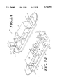
- FIG. 14A illustrates a syringe mounted within the front end of the driver device constructed according to one embodiment of the invention.
- FIG. 14B is a perspective view of a front end, partially cut away, of the driver device illustrated in FIG. 14A.
- FIG. 15A is a detailed view of a male luer lock fitting.
- FIGS. 15B and C are detailed views of alternative adapter elements useful with the microbore tubing assembly.
- FIG. 16 illustrates another embodiment of the driver device of the invention.
- FIG. 17 is an exploded view of the driver device of FIG. 16.
- the syringe driver of the invention is useful to facilitate multiple sequential doses of a fluid, such as a medicament, from a syringe at a controlled, predetermined flow rate.
- the driver device 10 as illustrated in FIGS. 1-9, comprises a frame 12, a carriage 14, a syringe 16, mounted within the frame, and an outflow tubing assembly 18.
- the syringe 16 used with the driver device can be any type of syringe used to dispense medical fluids such as medicaments and the like.
- the syringe can be of any one of a variety of sizes, ranging, for example, from 5 cc to 60 cc volume capacity.
- the syringe includes a barrel (with graduated markings) 20, an outlet tip 22 at the distal end of the syringe, which connects to outflow tubing assembly 18, a syringe plunger 24, a syringe flange 23, and a plunger disk 26 at a proximal end of the plunger.
- the plunger is slidable between withdrawn and inserted positions to expel fluid from within the syringe barrel.
- the frame 12 has distal 25, and proximal 27 ends, and comprises a track 28, formed of adjacent, parallel rails 30, 32.
- a carriage 14 is mounted upon the rails 30, 32 of track 28 at the proximal end 27 of the frame, and is able to slide along the track proximally and distally.
- the distal end 25 of the frame 12 includes a syringe mounting element 36 which secures the syringe within the frame 12.
- FIGS. 1-5 illustrate an embodiment in which the syringe mounting element 36 is a yoke element 38 that mates with the syringe flange 23 to help secure the syringe 20 within the frame 12.
- the yoke element 38 also acts as an end stop for the carriage motion.
- the yoke element 38 comprises a longitudinal groove structure 40 for receiving the syringe barrel 24 and plunger assembly.
- the space separating the adjacent gripping flange 46 and the distal flange 48 forms a transverse slot 50 which is able to engage securely the syringe flange 23, such as through a mechanical fit.
- the yoke element 38 also serves to prevent movement of the syringe barrel 20, in the proximal or distal directions, relative to the syringe plunger 24.
- the syringe mounting element 36 can also be in the form of a socket element 54 which cooperatively engages and supports the distal end 56 of syringe 16 and/or the proximal portion of outflow tubing assembly 18.
- the socket element 54 is shaped and dimensioned to cooperatively engage the distal end 56 of the syringe.
- Socket 54 preferably, includes an aperture 58 through which the outlet tip 22 of the syringe, the male luer 67, and the outflow tubing 18 may extend.
- the socket element 54 may be dimensioned selectively to engage and support an adapter element 34 of the microbore tubing assembly 18 shown in FIGS. 15B and 15C.
- the proximal end 27 of the frame 12 includes a stop element 52 for preventing further proximal movement of the carriage 14.
- a hanger device 53 is associated with the stop 52 to enable the apparatus to be suspended.
- the carriage 14 includes a structure that enables the carriage to mount and slide upon rails 30, 32 of frame track 28.
- the carriage may include a longitudinally oriented slot 60 on each side of the carriage.
- the slot 60 mates with a horizontal lip 62 formed on each rail 30, 32. This engagement allows the carriage to slide freely on the track 28, while at the same time preventing any vertical, dislodging movement of the carriage.
- the carriage 14 comprises a housing 15 which contains a spring element 66.
- a piston device 68 is displaceably positioned within and is biased to project from an aperture 70 formed in a distal end 72 of the housing.
- Dual finger grip flanges 74 also extend from the distal end of the housing.
- Each finger grip flange comprises an outwardly flared finger grip element 76.
- the interior surface of each finger grip flange includes an anti-siphon latch or stop element 78 that prevents further distal movement of the syringe plunger (relative to the syringe barrel) independent of movement of the carriage or piston 68.
- Cooperating locking elements are associated with the carriage 14 and the frame 12 to secure the carriage to the frame.
- the cooperating locking elements enable the carriage to be secured in the following positions: (i) an unlocked position; (ii) at least one locked, force applying position in which the piston 68 is at least partially retracted within the carriage; and (iii) a locked, non-force applying position in which the piston 68 is fully extended from the carriage.
- the cooperating locking elements can comprise the combination of a pawl mechanism 80 formed on the carriage and a plurality of detents 82 formed on at least one of rails 30, 32.
- Detents 82 can be of virtually any useful shape and dimension.
- FIGS. 8 and 9 illustrate an exemplary detent shape in which a distal part of detents 82 has a wall 201 which angles outwardly at a gradual rate before reaching a rounded out detent area 203 that it bordered, at its proximal end, by wall 205.
- each detent 82 can span a distance, from proximal to distal ends, of about 0.2 to 0.4 inch, and have a depth, at its detent area 203, of about 0.1 to 0.2 inch.
- FIGS. 1 through 5 illustrate that the proximal end of the housing contains a release button 64.
- the release button which can be mounted on a side of the housing, is a spring loaded pawl mechanism that engages detents or grooves 82 formed in an interior surface of one of rails 30, 32 of the track 28. Compression of the release button 64 retracts the pawl 80 and allows the carriage to move forward (distally) or rearward (proximally) within the track 28. Once the pawl 80 is released it is forced (e.g., by spring biasing) against the interior wall 86 of the rail 30. Linear movement of the carriage is possible until the pawl 80 encounters a detent 82.
- the carriage piston 68 can be in the form of a hollow cylinder that is closed at the distal end 88 thereof that projects from the aperture 70 of housing 15.
- the proximal end of the piston comprises a collar 90 having an increased diameter.
- the interior of the housing 15 optionally includes a dowel 94 which may extend the length of the housing and into the hollow, internal portion of the piston 68.
- the dowel preferably is able to extend through an opening (not shown) in the proximal wall of the housing.
- FIG. 7 illustrates that a compression spring 66 may be mounted around the dowel 94, which extends from a distal end 98 abutting the interior distal end wall 99 of the piston 68 to the interior proximal wall 100 of the housing. As so configured, the piston is biased by the spring element 96 to the extended position.
- the driver device is intended to be fitted with a specific syringe and to deliver a single, specific dose of a medical fluid following spring actuation.
- Such limitations are mainly enforced by (i) the shape and size of the syringe mounting yoke, (ii) the number and locations of ratcheting detents on the track, (iii) the limit of travel of the carriage piston, and (iv) the shape and location of antisiphon stop elements 78.
- the syringe mounting element 36 preferably is sized such that a syringe smaller than the correct size for a given driver device will immediately fall out of the driver device, and one of too large a diameter cannot be snapped into place within the driver device. Similarly, a differently proportioned syringe, such as one from a different manufacturer, cannot properly be fitted within the yoke.
- the syringe mounting element 36 also serves to contact and restrain a portion of the syringe, such as the syringe flange or the distal end of the syringe, to maintain the position of the syringe body longitudinally when force is applied to the syringe plunger, or hydrostatic forces (negative pressure) are applied to the outlet tip 22 by the action of gravity on the column of fluid in the tubing assembly 18.
- syringe mounting element and the portion of the frame or track containing the detents may be fabricated as separate components that are joined to the remainder of the device during assembly.
- a spacer, collar, or other retaining element may be added to the carriage piston to further limit its travel within the housing. In this way, variations of the device may be created with a minimum of additional expense.
- An example of one modification is to provide 5 cc, rather than 10 cc, doses for use in pediatric drug delivery. This modification can be accomplished by doubling the number of detents and by adding a collar or other device to limit the travel of the carriage piston to approximately half of its original range.
- FIGS. 1-5 illustrate an embodiment of the invention in which the syringe mounting element 36 comprises yoke 38 which engages syringe flange 23.
- the syringe mounting element 36 comprises a socket element 54 formed at a distal end of the frame 12. Socket element 54 preferably engages a distal end 56 of the syringe 20 while an aperture 58 in the socket engages an element, such as a male luer fitting 67, on the outflow tubing 18.
- the socket element 54 may selectively engage an adapter element 34 of the microbore tubing assembly.
- an overhanging lip (not shown) disposed on the distal end of the frame 12 may provide antisiphon protection by preventing proximal movement of the barrel under conditions of negative pressure.
- a distal end of frame 12 can include an angled ramp portion 65 which will eject from the driver any syringe that is too large or too small for the driver or any syringe which has mounted to it a tubing assembly with an adapter element 34 which is non-cooperating with socket element 54.
- a syringe can be mounted within frame 12 by angularly inserting the distal end 56 of the syringe into the syringe mounting element 36. Next, the syringe is forced downwardly until the syringe plunger is properly positioned adjacent the piston (not shown).
- FIGS. 10-12 illustrate an embodiment of the invention in which frame 12 may include a hinge 106 to facilitate folding of the frame.
- the syringe securing element 36 is formed by a socket 54 having an aperture 58 which accommodates a distal end 25 of syringe 16 or a proximal end of the tubing assembly.
- FIG. 13 illustrates a similar embodiment in which frame 12 is telescoping rather than folding.
- the frame includes a female portion 12A and a male portion 12B.
- a detent tab 121 is formed in a forward end of frame portion 12A. In the open position the detent 121 extends through an aperture 123 formed in the frame portion 12A to lock the frame in the open position.
- the frame can be closed by simply depressing tab element 121 and sliding frame portion 12B within frame portion 12A.
- FIGS. 3A through 3D sequentially illustrate the manner in which the driver device of the invention may be utilized, e.g., to deliver the first of a total of four medication doses.
- the carriage 14 Before the syringe 16 is mounted, the carriage 14 is placed in its fully retracted position at the proximal end 27 of the track 28. Proper insertion of the syringe places the syringe plunger disk 26 so that it is adjacent to the extended carriage piston 68 and contained by the two anti-siphon latches 78. (See FIG. 3A). The extension of the carriage piston 68 is caused by force applied to it by the main spring 66 and is limited by an internal stop (e.g., the collar 90 of the piston). A length of microbore tubing 18 of known dimensions (i.e., length and internal diameter) and performance (i.e., resistance to flow of a specified fluid) is connected to the outlet port 22 of the syringe.
- a length of microbore tubing 18 of known dimensions (i.e., length and internal diameter) and performance (i.e., resistance to flow of a specified fluid) is connected to the outlet port 22 of the syringe.
- the carriage is advanced forwardly (distally) along the track 28 by manual external force until the pawl 80 engages a desired detent 82 in the track.
- the carriage piston 68 exerts a force on the syringe plunger 24 and neither the piston nor the plunger can advance due to the presence of fluid in the syringe, the flow of which is restricted by the small diameter of the microbore tubing. This action causes the main spring 66 within the carriage to compress and thereby to apply a driving force to the plunger through the piston.
- the design of the pawl and the detents in the track, shown in FIGS. 8 and 9, and the biasing force of the auxiliary pawl biasing spring (now shown) are optimized for several considerations.
- a rearward force of the main spring will not free the pawl from a detent.
- a moderate advancing force is needed to lift the pawl out of a detent, such as by a human user advancing the carriage distally to begin medication delivery.
- the force needed to lift the pawl out of a detent is sufficient to resist previously described typical negative pressures within the syringe barrel as may act on the locking elements through the plunger disk, anti-siphon stop elements 78 and carriage housing 15.
- the detents are so positioned that, until a given dose is completed, it is impossible to advance the pawl into the detent corresponding to the following dose. If such an attempt is made, the carriage will advance only a limited distance and will spring back to its correct positions as soon as the external force is removed.
- a dose is to be delivered from a partially-filled syringe (e.g., containing, for example, only two of four possible 10-ml doses)
- the user first observes (using the graduated markings on the syringe barrel) the fill volume of the syringe, in this instance 20 ml.
- the carriage is then advanced (by depressing release button 64) distally along the rails of the frame, with a manual sliding motion until the pawl engages the detent corresponding to the locked, non force-applying position for a syringe filled to 20 ml.
- a rail (30)--mounted label assists the user in so positioning the carriage.
- the syringe is then inserted, and the spring is actuated for dose delivery, as described above. Confirmation of dose completion is visual by the user, involving observation of device status and plunger tip position with respect to the graduated markings on the syringe barrel.
- driver device of the invention delivers multiple doses of fluid from a single syringe and that delivery of each dose is initiated by recompressing a drive spring by a simple, individual, manual action such that inadvertent delivery of multiple doses by an individual action is impossible.
- Another feature of the driver device of the invention is that one is able to advance the carriage by applying manual force to the two adjacent grip flanges 74 on the carriage and the two adjacent gripping flanges 46 that form part of the syringe mounting element 36.
- These elements allow the user to grip the device with the thumb and forefinger of both hands and easily to apply sufficient force to advance the carriage.
- These grips are positioned so that they are within the natural range of motion of an ordinary adult hand. The apparatus does not require additional space or clearance during the operation of advancing the carriage.
- An additional feature of the invention relates to removal of the syringe and retraction of the carriage. After all doses have been expelled from the syringe, the syringe may be lifted away from the apparatus with a snapping action.
- the release button 64 on the side of the carriage, connected to the pawl 80, is depressed causing the pawl 80 to retract into the carriage body. While holding the release button down, the user may easily slide the carriage to its fully retracted position at the proximal end of the frame 12 so that a new syringe may be inserted.
- the driver device of the invention includes an anti-siphon element which prevents movement of the plunger independent of movement of the carriage or the force applying element.
- This element is intended to prevent the syringe plunger from being drawn into the syringe barrel if negative pressure is applied to the syringe outlet port via the connecting tubing, causing an inadvertent delivery of additional fluid.
- the anti-siphon element comprises of a pair of latches 78 formed on the internal surfaces of grip flanges 74 that constrain the syringe plunger disk.
- the gripping flange 46, in cooperation with the distal flange 48 helps to constrain the syringe flange 23. The combination of these elements prevents the plunger 24 from moving forward into the syringe barrel 20 after a dose is completed, and also prevents the syringe barrel 20 from sliding backwards over the plunger.
- the shape of the latches 78 is such that if syringe plunger disk 26 is not fully constrained by the latches 78 during insertion into the device, a sharp advancing force, manually applied, will cause the latches 78 to snap over the plunger disk 26 and to be properly engaged by the latches. The first dose cannot be initiated until this action has been taken.
- a pivoting arm 118 has a substantially centrally located pivot 120 mounted on a laterally protruding portion 122 of the arm.
- a proximal end of arm 118 includes a ratcheting pawl 114 while a distal end of arm 126 includes a tapered catch 116.
- the arm 118 mounts within carriage 14, as shown in FIGS. 18 and 19, such that a spring mechanism (not shown) biases the pawl 114 into contact with detents (not shown) in the track 28.
- the catch 116 engages the syringe plunger disk 26 whenever the plunger disk 26 is disposed within plunger housing 124 appended to the distal end of carriage 14.
- the geometry of the pivoting arm 118 is such that any pulling force on the catch 116 (due to a potential siphoning action) tends to increase the holding force on the detent and thus prevents movement of the carriage.
- the release button 128, which is attached to the pawl both the pawl 114 and the catch 116 are disengaged, allowing the carriage 14 to be retracted and the syringe to be released for unloading.
- An additional feature of the invention is that the spring force applied to the syringe plunger 24 does not change significantly during the travel required to deliver a dose. Accordingly, the flow rate also does not change significantly during delivery of the dose.
- the spring is compressed to less than about half of its unstressed length before being assembled into the carriage. The additional compression of the spring required to advance the carriage during use is only a small fraction of the total compression applied to the spring, resulting in only a small change in reaction force. Further, the spring is recompressed for each dose. Because the spring need only be compressed sufficiently to deliver a single dose, rather than multiple doses, it must be compressed only a small amount for subsequent doses in addition to the compression provided during assembly of the apparatus.
- a further advantage of the driver device of the invention is that a simple coil spring is preferably employed as the main spring 66. This spring acts directly in line with the syringe plunger, minimizing frictional forces that might act to disturb the force applied to the syringe.
- the adapter element 34 of the microbore tubing assembly can have a non-standard geometry and/or dimensions that are adapted to fit only within complementarily sized and shaped sockets 54 of the syringe mounting element 36, as described above.
- FIG. 15A illustrates a typical male luer fitting 67 which may form a proximal end of the microbore tubing assembly 18 to facilitate connection to the syringe.
- FIGS. 15B and C illustrate different embodiments of an adapter element 34 for a microbore tubing assembly 18. In these embodiments the adapter is illustrated to be generally oval or circle-shaped, however various other geometries may be used as well.
- Proximal to adapter 34 is a male Luer lock fitting 67 which can mate with outlet tip 22 and female luer components of syringe distal end 56.
- filled syringes are distributed with a tubing set attached or in a combined package. Operating protocol would require that such syringes always be used with the tubing sets with which they are packaged, and that any unused syringes or tube sets must be disposed of or returned to the distributor.
- Table 1 illustrates the approximate spring force and length requirements for use of 20 cc and 60 cc syringes, in which units are in inches and pounds.
- the smaller syringe requires lower force because of its smaller piston area.
- spring wire diameter and spring length and pitch By appropriate choice of spring wire diameter and spring length and pitch, a ratio of maximum to minimum force can be maintained comparable to that used with the 60 cc syringe, without greatly extending the working spring length.
- spring force of about 8 pounds is suitable for use with a 60 cc syringe.
- the flow rate through a circular tube under laminar conditions is determined by Poisseuille's law, which can be stated as: ##EQU1## where Q is the volumetric flow rate, r is the internal radius of the tube, ⁇ is the fluid viscosity, L is the length of the tube, and p is the pressure drop along the tube length.
- the pressure drop can be expanded as:
- p i is the applied pressure at the inlet end
- p o is the applied pressure at the outlet end
- g is the gravitational constant
- z is the difference in height between the two ends of the tube.
- p o is the venous blood pressure of the patient (typically less than 10 cm H 2 0)
- z is the height of the syringe relative to the patient's body.
- the inlet pressure, p i is the force, F, acting on the syringe plunger divided by the plunger surface area, A, and less the friction loss between the plunger and syringe wall, n.
- the force generated by the compressed spring is known from Hooke's law. In this case Hooke's law may be written as:
- k is the spring constant (essentially the stiffness of the spring)
- l p is the pre-load deflection applied during assembly
- l d is the additional deflection applied to activate a dose.
- Mechanical considerations require that l p always be somewhat less than the unloaded spring length, particularly for compression springs.
- the value of l d is at a maximum at the start of a dose, and goes to zero at the completion of a dose.
- the design of the present invention provides for l d to be small compared to l p , and, as can be seen from the above equation, this minimizes the change in force during a dose.
Landscapes
- Health & Medical Sciences (AREA)
- Vascular Medicine (AREA)
- Engineering & Computer Science (AREA)
- Anesthesiology (AREA)
- Biomedical Technology (AREA)
- Heart & Thoracic Surgery (AREA)
- Hematology (AREA)
- Life Sciences & Earth Sciences (AREA)
- Animal Behavior & Ethology (AREA)
- General Health & Medical Sciences (AREA)
- Public Health (AREA)
- Veterinary Medicine (AREA)
- Infusion, Injection, And Reservoir Apparatuses (AREA)
Priority Applications (2)
| Application Number | Priority Date | Filing Date | Title |
|---|---|---|---|
| US08/696,479 US5722956A (en) | 1995-08-24 | 1996-08-14 | Multi-dose syringe driver |
| US09/030,093 US5954695A (en) | 1995-08-24 | 1998-02-25 | Multi-dose syringe driver |
Applications Claiming Priority (2)
| Application Number | Priority Date | Filing Date | Title |
|---|---|---|---|
| US277195P | 1995-08-24 | 1995-08-24 | |
| US08/696,479 US5722956A (en) | 1995-08-24 | 1996-08-14 | Multi-dose syringe driver |
Related Child Applications (1)
| Application Number | Title | Priority Date | Filing Date |
|---|---|---|---|
| US09/030,093 Continuation US5954695A (en) | 1995-08-24 | 1998-02-25 | Multi-dose syringe driver |
Publications (1)
| Publication Number | Publication Date |
|---|---|
| US5722956A true US5722956A (en) | 1998-03-03 |
Family
ID=21702429
Family Applications (2)
| Application Number | Title | Priority Date | Filing Date |
|---|---|---|---|
| US08/696,479 Expired - Lifetime US5722956A (en) | 1995-08-24 | 1996-08-14 | Multi-dose syringe driver |
| US09/030,093 Expired - Fee Related US5954695A (en) | 1995-08-24 | 1998-02-25 | Multi-dose syringe driver |
Family Applications After (1)
| Application Number | Title | Priority Date | Filing Date |
|---|---|---|---|
| US09/030,093 Expired - Fee Related US5954695A (en) | 1995-08-24 | 1998-02-25 | Multi-dose syringe driver |
Country Status (10)
| Country | Link |
|---|---|
| US (2) | US5722956A (de) |
| EP (1) | EP0959916B1 (de) |
| JP (1) | JPH11514255A (de) |
| CN (1) | CN1193917A (de) |
| AT (1) | ATE253387T1 (de) |
| AU (1) | AU705032B2 (de) |
| CA (1) | CA2229547A1 (de) |
| DE (1) | DE69630620D1 (de) |
| MX (1) | MX9801372A (de) |
| WO (1) | WO1997007838A1 (de) |
Cited By (45)
| Publication number | Priority date | Publication date | Assignee | Title |
|---|---|---|---|---|
| US5944693A (en) * | 1998-08-17 | 1999-08-31 | Jacobs; Warren A | Syringe assembly and associated syringe biasing device |
| US5954695A (en) * | 1995-08-24 | 1999-09-21 | The General Hospital Corporation | Multi-dose syringe driver |
| US5968015A (en) * | 1997-03-05 | 1999-10-19 | Sugan Co., Ltd. | Injector head for medical use |
| US6110149A (en) * | 1996-09-13 | 2000-08-29 | Novo Nordisk A/S | Syringe |
| WO2001019428A2 (en) | 1999-09-13 | 2001-03-22 | Vitro Diagnostics, Inc. | Multi-dose syringe driver |
| US6530371B2 (en) * | 1999-10-14 | 2003-03-11 | Becton, Dickinson And Company | Drug delivery system including holder and drug container |
| US20030163090A1 (en) * | 2002-02-28 | 2003-08-28 | Blomquist Michael L. | Syringe pump control systems and methods |
| US20030161744A1 (en) * | 2002-02-28 | 2003-08-28 | Vilks Clinton S. | Cartridge and pump with axial loading |
| US6626862B1 (en) * | 2000-04-04 | 2003-09-30 | Acist Medical Systems, Inc. | Fluid management and component detection system |
| US6652493B1 (en) * | 2000-07-05 | 2003-11-25 | Animas Corporation | Infusion pump syringe |
| US6676635B2 (en) * | 2000-02-10 | 2004-01-13 | Nemoto Kyorindo Co., Ltd. | Syringe barrel and cylinder holder |
| US20040249276A1 (en) * | 2003-06-09 | 2004-12-09 | Shigeru Nemoto | Liquid injection system with cylinder adapter holding cylinder flange of liquid syringe with pair of movable holders |
| US20060069354A1 (en) * | 2004-09-30 | 2006-03-30 | Buenger David R | Syringe activation device |
| US20060069350A1 (en) * | 2004-09-30 | 2006-03-30 | Buenger David R | Medical syringe injector pen |
| US20060178634A1 (en) * | 2004-12-06 | 2006-08-10 | Wyrick Ronald S | Medicine injection devices and methods |
| US20060186143A1 (en) * | 2005-02-24 | 2006-08-24 | Boston Scientific Santa Rosa Corporation | Constant force material delivery system and method |
| US20070017533A1 (en) * | 2004-12-06 | 2007-01-25 | Washington Biotech Corporation | Method and apparatus for delivering epinephrine |
| US20070191784A1 (en) * | 2004-03-30 | 2007-08-16 | Jacobs Alexander T | Medication dispensing apparatus with gear set having drive member accommodating opening |
| US20070197976A1 (en) * | 2004-03-30 | 2007-08-23 | Jacobs Alexander T | Medication dispensing apparatus with spring-driven locking feature enabled by administration of final dose |
| US20070203247A1 (en) * | 2006-02-28 | 2007-08-30 | Elaine Phillips | Epinephrine dosing regimens |
| US20070233004A1 (en) * | 2006-03-29 | 2007-10-04 | The General Hospital Corporation D/B/A Massachusetts General Hospital | Single-Dose Syringe Driver |
| US20070293582A1 (en) * | 2006-06-05 | 2007-12-20 | Malcolm Hill | Epinephrine dosing regimens comprising buccal, lingual or sublingual and injectable dosage forms |
| US20080021396A1 (en) * | 2005-10-28 | 2008-01-24 | Ahmad Momeni | Syringe assist for infusion pump |
| US20080039789A1 (en) * | 2004-12-06 | 2008-02-14 | Wyrick Ronald E | Medicine injection devices and methods |
| US20080243057A1 (en) * | 2002-06-21 | 2008-10-02 | Jacobson James D | Fluid delivery system and flow control therefor |
| US20090043239A1 (en) * | 2005-05-27 | 2009-02-12 | Alfred Gagel | Device and method for transporting medicinal liquids |
| US20090192460A1 (en) * | 2008-01-29 | 2009-07-30 | Medmix Systems Ag | Device with pressure-actuated pistons for dispensing a multiple syringe or multiple cartridge |
| US20100137841A1 (en) * | 2006-10-06 | 2010-06-03 | Khouri Roger K | Constant Pressure Syringe For Surgical Use |
| US20100212663A1 (en) * | 2002-09-27 | 2010-08-26 | Becton, Dickinson & Company | Spray or Injection Device Allowing at Least Two Preset Doses of Product to be Delivered |
| US20100286654A1 (en) * | 2009-05-06 | 2010-11-11 | Cesario Pereira Dos Santos | Multiple Thermal Sensors in a Multiple Processor Environment for Temperature Control in a Drug Delivery Device |
| US7914499B2 (en) | 2006-03-30 | 2011-03-29 | Valeritas, Inc. | Multi-cartridge fluid delivery device |
| US20110152767A1 (en) * | 2009-12-22 | 2011-06-23 | Pinedjian Raffi S | Method and Apparatus for Drug Delivery |
| US20110226646A1 (en) * | 2004-12-06 | 2011-09-22 | Wyrick Ronald E | Kits Containing Medicine Injection Devices And Containers |
| US8070726B2 (en) | 2003-04-23 | 2011-12-06 | Valeritas, Inc. | Hydraulically actuated pump for long duration medicament administration |
| US8366682B2 (en) | 2009-03-04 | 2013-02-05 | Washington Biotech Corporation | Medicine injection apparatuses |
| US8939959B2 (en) | 2008-01-30 | 2015-01-27 | Becton, Dickinson And Company | Dose dividing delivery device |
| US9089636B2 (en) | 2004-07-02 | 2015-07-28 | Valeritas, Inc. | Methods and devices for delivering GLP-1 and uses thereof |
| US9168562B2 (en) | 2013-10-10 | 2015-10-27 | Ann Gilchrist | Syringe-assist device and method for utilizing the same |
| WO2020172323A1 (en) * | 2019-02-19 | 2020-08-27 | Kwolek Marilyn | Exostructure to assist in accurate syringe injection |
| US10881809B2 (en) | 2017-08-22 | 2021-01-05 | KB Medical, LLC | Exostructure to assist in accurate syringe injection |
| US11123494B2 (en) | 2017-08-22 | 2021-09-21 | KB Medical, LLC | Exostructure to assist in accurate syringe injection |
| WO2021236992A1 (en) * | 2020-05-20 | 2021-11-25 | Betaglue Technologies S.P.A. | Methods and apparatus for controlled delivery of a sealant |
| US11883260B2 (en) | 2014-12-23 | 2024-01-30 | Automed Patent Holdco, Llc | Delivery apparatus, system and associated methods |
| US11957542B2 (en) | 2020-04-30 | 2024-04-16 | Automed Patent Holdco, Llc | Sensing complete injection for animal injection device |
| WO2024191637A1 (en) * | 2023-03-14 | 2024-09-19 | Carefusion 303, Inc. | Intravenous set with syringe interface for rapid infusion via reusable driver |
Families Citing this family (33)
| Publication number | Priority date | Publication date | Assignee | Title |
|---|---|---|---|---|
| US6807965B1 (en) | 1998-06-03 | 2004-10-26 | Scott Laboratories, Inc. | Apparatus and method for providing a conscious patient relief from pain and anxiety associated with medical or surgical procedures |
| US6471674B1 (en) | 2000-04-21 | 2002-10-29 | Medrad, Inc. | Fluid delivery systems, injector systems and methods of fluid delivery |
| IL156245A0 (en) * | 2000-12-22 | 2004-01-04 | Dca Design Int Ltd | Drive mechanism for an injection device |
| EP1351730B1 (de) * | 2001-01-18 | 2006-06-28 | Medrad, Inc. | Spritzenanschlussflächen und adaptern für verwendung mit medizinische injektoren |
| US7223253B2 (en) * | 2002-07-29 | 2007-05-29 | Gore Enterprise Holdings, Inc. | Blood aspiration system and methods of use |
| US7539537B2 (en) | 2002-10-03 | 2009-05-26 | Scott Laboratories, Inc. | Systems and methods for providing sensor fusion |
| AU2003275460A1 (en) | 2002-10-03 | 2004-04-23 | Scott Laboratories, Inc. | Systems and methods for providing trend analysis in a sedation and analgesia system |
| US20060173439A1 (en) * | 2005-01-18 | 2006-08-03 | Thorne Gale H Jr | Syringe drive system |
| CA2743320A1 (en) * | 2008-10-31 | 2010-05-06 | Mallinckrodt Inc. | Multi-dose injection system |
| JP5428465B2 (ja) * | 2009-03-31 | 2014-02-26 | パナソニック株式会社 | シリンジ駆動装置 |
| DK2243505T3 (en) | 2009-04-23 | 2018-04-30 | Bayer Healthcare Llc | Spraying devices and methods of producing spraying devices |
| WO2011022618A1 (en) | 2009-08-21 | 2011-02-24 | Becton Dickinson France Sas | Pre-filled active vial having integral plunger assembly |
| JP5172866B2 (ja) * | 2010-01-05 | 2013-03-27 | 株式会社根本杏林堂 | シリンジ、シリンダホルダ、および薬液注入システム |
| CA2736841C (en) * | 2010-04-15 | 2014-02-18 | Teneo Innovations Inc. | Device and electronic controller for syringe piston control |
| CN106110518A (zh) | 2010-06-04 | 2016-11-16 | 拜耳医药保健有限责任公司 | 用于规划和监测在放射性药物注射器上的多剂量放射性药物使用的系统和方法 |
| US20120071837A1 (en) * | 2010-09-21 | 2012-03-22 | O'connor Sean | Auto injector for medication |
| CN102188764B (zh) * | 2011-03-14 | 2015-12-02 | 张亚根 | 一种加压注射器及附件 |
| JP5173055B2 (ja) * | 2012-07-24 | 2013-03-27 | 株式会社根本杏林堂 | シリンジ、シリンダホルダ、および薬液注入システム |
| JP5173054B2 (ja) * | 2012-07-24 | 2013-03-27 | 株式会社根本杏林堂 | シリンジ、シリンダホルダ、および薬液注入システム |
| WO2014046950A1 (en) | 2012-09-24 | 2014-03-27 | Enable Injections, Llc | Medication vial and injector assemblies and methods of use |
| EP4144390A3 (de) | 2013-06-18 | 2023-07-12 | Enable Injections, Inc. | Phiolenübertragungs- und -injektionsvorrichtung und -verfahren |
| EP2829290A1 (de) * | 2013-07-25 | 2015-01-28 | Sanofi-Aventis Deutschland GmbH | Antriebseinheit für eine Arzneimittelabgabevorrichtung |
| AU2014360278B2 (en) | 2013-12-06 | 2017-08-17 | Teleflex Medical Incorporated | Dose divider syringe |
| JP5944451B2 (ja) * | 2014-09-04 | 2016-07-05 | 株式会社根本杏林堂 | シリンジ、シリンダホルダ、および薬液注入システム |
| AU2015360273B2 (en) | 2014-12-12 | 2020-05-07 | Wake Forest University Health Sciences | Incremental syringe |
| MY197087A (en) | 2016-06-27 | 2023-05-24 | Takeda Pharmaceuticals Co | Syringe stabilizer |
| CN109550117A (zh) * | 2016-12-09 | 2019-04-02 | 王才丰 | 无针注射器终端注射组件的取药装置 |
| CN110402157A (zh) * | 2017-03-16 | 2019-11-01 | 泰尔茂株式会社 | 药液给予装置 |
| US11655302B2 (en) | 2019-06-10 | 2023-05-23 | Sanofi | Anti-CD38 antibodies and formulations |
| EP4069743A1 (de) | 2019-12-05 | 2022-10-12 | Sanofi-Aventis U.S. LLC | Formulierungen von anti-cd38-antikörpern zur subkutanen verabreichung |
| WO2022235703A1 (en) * | 2021-05-03 | 2022-11-10 | The Children's Hospital Of Philadelphia | Syringes and controllers for the same |
| CN114522298B (zh) * | 2022-01-07 | 2024-03-15 | 王奇剑 | 一种微量注射泵 |
| EP4342508A1 (de) * | 2022-09-21 | 2024-03-27 | Trasis S.A. | Vorrichtung zum ankoppeln einer spritze an einen aktuator |
Citations (26)
| Publication number | Priority date | Publication date | Assignee | Title |
|---|---|---|---|---|
| US2632445A (en) * | 1951-10-20 | 1953-03-24 | Sr John L Kas | Dosing hypodermic syringe |
| US4059110A (en) * | 1976-10-07 | 1977-11-22 | Timex Corporation | Clockwork driven hypodermic syringe |
| US4132231A (en) * | 1977-05-20 | 1979-01-02 | Vincent Puccio | Injection device |
| US4202333A (en) * | 1978-11-08 | 1980-05-13 | Minnesota Mining And Manufacturing Company | Fluid dispensing device |
| US4298000A (en) * | 1978-11-08 | 1981-11-03 | Minnesota Mining And Manufacturing Company | Fluid dispensing device |
| US4430079A (en) * | 1978-11-08 | 1984-02-07 | Minnesota Mining And Manufacturing Company | Fluid dispensing device |
| US4465478A (en) * | 1982-10-14 | 1984-08-14 | Collagen Corporation | Syringe force amplification device |
| US4498904A (en) * | 1981-02-12 | 1985-02-12 | Turner Robert C | Dose metering plunger devices for use with syringes |
| US4544369A (en) * | 1983-11-22 | 1985-10-01 | C. R. Bard, Inc. | Battery operated miniature syringe infusion pump |
| US4547189A (en) * | 1984-03-05 | 1985-10-15 | John A. Long | Insulin syringe injector apparatus with auto-aspirator feature |
| US4608042A (en) * | 1985-09-25 | 1986-08-26 | Warner-Lambert Company | Apparatus for sequential infusion of medical solutions |
| US4636197A (en) * | 1985-02-15 | 1987-01-13 | Ping Chu | Intravenous fluid infusion device |
| US4652260A (en) * | 1985-03-11 | 1987-03-24 | Strato Medical Corporation | Infusion device |
| US4676122A (en) * | 1984-06-15 | 1987-06-30 | Daltex Medical Sciences, Inc. | Fail-safe mechanical drive for syringe |
| US4804368A (en) * | 1986-12-05 | 1989-02-14 | C. R. Bard, Inc. | Battery operated miniature syringe infusion pump and improved halfnut therefor |
| US4943279A (en) * | 1988-09-30 | 1990-07-24 | C. R. Bard, Inc. | Medical pump with infusion controlled by a detachable coded label |
| US5004124A (en) * | 1988-12-08 | 1991-04-02 | The Trustees Of Columbia In The City Of New York | Method and apparatus for dispensing a fluid substance |
| US5092842A (en) * | 1987-05-08 | 1992-03-03 | Wilhelm Haselmeier Gmbh & Co. | Injection device with a cocking element and a second setting element |
| US5140862A (en) * | 1991-02-06 | 1992-08-25 | Pappalardo Joseph T | Injection pump calibration device |
| US5176646A (en) * | 1991-02-19 | 1993-01-05 | Takayuki Kuroda | Motorized syringe pump |
| US5232459A (en) * | 1989-01-13 | 1993-08-03 | Kabi Pharmacia Ab | Multi-dose syringe |
| US5300041A (en) * | 1992-06-01 | 1994-04-05 | Habley Medical Technology Corporation | Dose setting and repeating syringe |
| US5318539A (en) * | 1986-10-17 | 1994-06-07 | Alexander G. B. O'Neil | Liquid feeding apparatus utilizing capillary tubing, and syringe driver |
| US5328486A (en) * | 1991-11-19 | 1994-07-12 | American Cyanamid Company | Syringe for dispensing multiple dosages |
| US5429607A (en) * | 1994-03-09 | 1995-07-04 | I-Flow Corporation | Elastomeric syringe actuation device |
| US5599315A (en) * | 1995-12-01 | 1997-02-04 | Charles J. McPhee | Syringe actuation device |
Family Cites Families (3)
| Publication number | Priority date | Publication date | Assignee | Title |
|---|---|---|---|---|
| DE69203472T2 (de) * | 1991-02-07 | 1996-01-04 | Terumo Corp | Dosiereinrichtung für Injektor. |
| GB9310163D0 (en) * | 1993-05-18 | 1993-06-30 | Owen Mumford Ltd | Improvements relating to injection devices |
| US5722956A (en) * | 1995-08-24 | 1998-03-03 | The General Hospital Corporation | Multi-dose syringe driver |
-
1996
- 1996-08-14 US US08/696,479 patent/US5722956A/en not_active Expired - Lifetime
- 1996-08-23 AT AT96928975T patent/ATE253387T1/de not_active IP Right Cessation
- 1996-08-23 CN CN96196483A patent/CN1193917A/zh active Pending
- 1996-08-23 WO PCT/US1996/013545 patent/WO1997007838A1/en active IP Right Grant
- 1996-08-23 EP EP96928975A patent/EP0959916B1/de not_active Expired - Lifetime
- 1996-08-23 AU AU68544/96A patent/AU705032B2/en not_active Ceased
- 1996-08-23 JP JP9510411A patent/JPH11514255A/ja active Pending
- 1996-08-23 DE DE69630620T patent/DE69630620D1/de not_active Expired - Lifetime
- 1996-08-23 CA CA002229547A patent/CA2229547A1/en not_active Abandoned
-
1998
- 1998-02-19 MX MX9801372A patent/MX9801372A/es unknown
- 1998-02-25 US US09/030,093 patent/US5954695A/en not_active Expired - Fee Related
Patent Citations (27)
| Publication number | Priority date | Publication date | Assignee | Title |
|---|---|---|---|---|
| US2632445A (en) * | 1951-10-20 | 1953-03-24 | Sr John L Kas | Dosing hypodermic syringe |
| US4059110A (en) * | 1976-10-07 | 1977-11-22 | Timex Corporation | Clockwork driven hypodermic syringe |
| US4132231A (en) * | 1977-05-20 | 1979-01-02 | Vincent Puccio | Injection device |
| US4202333A (en) * | 1978-11-08 | 1980-05-13 | Minnesota Mining And Manufacturing Company | Fluid dispensing device |
| US4298000A (en) * | 1978-11-08 | 1981-11-03 | Minnesota Mining And Manufacturing Company | Fluid dispensing device |
| US4430079A (en) * | 1978-11-08 | 1984-02-07 | Minnesota Mining And Manufacturing Company | Fluid dispensing device |
| US4597754A (en) * | 1978-11-08 | 1986-07-01 | Minnesota Mining And Manufacturing Company | Long capillary tube hose assembly for fluid dispensing device |
| US4498904A (en) * | 1981-02-12 | 1985-02-12 | Turner Robert C | Dose metering plunger devices for use with syringes |
| US4465478A (en) * | 1982-10-14 | 1984-08-14 | Collagen Corporation | Syringe force amplification device |
| US4544369A (en) * | 1983-11-22 | 1985-10-01 | C. R. Bard, Inc. | Battery operated miniature syringe infusion pump |
| US4547189A (en) * | 1984-03-05 | 1985-10-15 | John A. Long | Insulin syringe injector apparatus with auto-aspirator feature |
| US4676122A (en) * | 1984-06-15 | 1987-06-30 | Daltex Medical Sciences, Inc. | Fail-safe mechanical drive for syringe |
| US4636197A (en) * | 1985-02-15 | 1987-01-13 | Ping Chu | Intravenous fluid infusion device |
| US4652260A (en) * | 1985-03-11 | 1987-03-24 | Strato Medical Corporation | Infusion device |
| US4608042A (en) * | 1985-09-25 | 1986-08-26 | Warner-Lambert Company | Apparatus for sequential infusion of medical solutions |
| US5318539A (en) * | 1986-10-17 | 1994-06-07 | Alexander G. B. O'Neil | Liquid feeding apparatus utilizing capillary tubing, and syringe driver |
| US4804368A (en) * | 1986-12-05 | 1989-02-14 | C. R. Bard, Inc. | Battery operated miniature syringe infusion pump and improved halfnut therefor |
| US5092842A (en) * | 1987-05-08 | 1992-03-03 | Wilhelm Haselmeier Gmbh & Co. | Injection device with a cocking element and a second setting element |
| US4943279A (en) * | 1988-09-30 | 1990-07-24 | C. R. Bard, Inc. | Medical pump with infusion controlled by a detachable coded label |
| US5004124A (en) * | 1988-12-08 | 1991-04-02 | The Trustees Of Columbia In The City Of New York | Method and apparatus for dispensing a fluid substance |
| US5232459A (en) * | 1989-01-13 | 1993-08-03 | Kabi Pharmacia Ab | Multi-dose syringe |
| US5140862A (en) * | 1991-02-06 | 1992-08-25 | Pappalardo Joseph T | Injection pump calibration device |
| US5176646A (en) * | 1991-02-19 | 1993-01-05 | Takayuki Kuroda | Motorized syringe pump |
| US5328486A (en) * | 1991-11-19 | 1994-07-12 | American Cyanamid Company | Syringe for dispensing multiple dosages |
| US5300041A (en) * | 1992-06-01 | 1994-04-05 | Habley Medical Technology Corporation | Dose setting and repeating syringe |
| US5429607A (en) * | 1994-03-09 | 1995-07-04 | I-Flow Corporation | Elastomeric syringe actuation device |
| US5599315A (en) * | 1995-12-01 | 1997-02-04 | Charles J. McPhee | Syringe actuation device |
Cited By (114)
| Publication number | Priority date | Publication date | Assignee | Title |
|---|---|---|---|---|
| US5954695A (en) * | 1995-08-24 | 1999-09-21 | The General Hospital Corporation | Multi-dose syringe driver |
| US6110149A (en) * | 1996-09-13 | 2000-08-29 | Novo Nordisk A/S | Syringe |
| US5968015A (en) * | 1997-03-05 | 1999-10-19 | Sugan Co., Ltd. | Injector head for medical use |
| US5944693A (en) * | 1998-08-17 | 1999-08-31 | Jacobs; Warren A | Syringe assembly and associated syringe biasing device |
| WO2001019428A2 (en) | 1999-09-13 | 2001-03-22 | Vitro Diagnostics, Inc. | Multi-dose syringe driver |
| US6530371B2 (en) * | 1999-10-14 | 2003-03-11 | Becton, Dickinson And Company | Drug delivery system including holder and drug container |
| US7695457B2 (en) | 2000-02-02 | 2010-04-13 | Nemoto Kyorindo Co., Ltd. | Syringe barrel with roughened surface |
| US20040087910A1 (en) * | 2000-02-10 | 2004-05-06 | Shigeru Nemoto | Syringe barrel with roughened surface |
| US6676635B2 (en) * | 2000-02-10 | 2004-01-13 | Nemoto Kyorindo Co., Ltd. | Syringe barrel and cylinder holder |
| US20040082919A1 (en) * | 2000-02-10 | 2004-04-29 | Shigeru Nemoto | Cylinder holder for a syringe barrel with rear surface projection |
| US7264612B2 (en) | 2000-02-10 | 2007-09-04 | Nemoto Kyorindo Co., Ltd. | Syringe barrel with guide |
| US20040087908A1 (en) * | 2000-02-10 | 2004-05-06 | Shigeru Nemoto | Cylinder holder for a syringe barrel |
| US20040087909A1 (en) * | 2000-02-10 | 2004-05-06 | Shigeru Nemoto | Syringe barrel with reinforcing rib |
| US20040092881A1 (en) * | 2000-02-10 | 2004-05-13 | Shigeru Nemoto | Syringe barrel with guide |
| US7393341B2 (en) | 2000-02-10 | 2008-07-01 | Shigeru Nemoto | Cylinder holder for a syringe barrel with rear surface projection |
| US7137967B2 (en) | 2000-02-10 | 2006-11-21 | Nemoto Kyorindo Co., Ltd. | Cylinder holder for a syringe barrel |
| US7344520B2 (en) | 2000-02-10 | 2008-03-18 | Nemoto Kyorindo Co Ltd | Syringe barrel with reinforcing rib |
| US6626862B1 (en) * | 2000-04-04 | 2003-09-30 | Acist Medical Systems, Inc. | Fluid management and component detection system |
| US6652493B1 (en) * | 2000-07-05 | 2003-11-25 | Animas Corporation | Infusion pump syringe |
| US20030161744A1 (en) * | 2002-02-28 | 2003-08-28 | Vilks Clinton S. | Cartridge and pump with axial loading |
| US20050234404A1 (en) * | 2002-02-28 | 2005-10-20 | Smiths Medical Md, Inc. | Cartridge and pump with axial loading |
| US7033338B2 (en) * | 2002-02-28 | 2006-04-25 | Smiths Medical Md, Inc. | Cartridge and rod for axially loading medication pump |
| US7041082B2 (en) | 2002-02-28 | 2006-05-09 | Smiths Medical Md, Inc. | Syringe pump control systems and methods |
| US7510544B2 (en) | 2002-02-28 | 2009-03-31 | Smiths Medical Md, Inc. | Cartridge and pump with axial loading |
| US7442186B2 (en) | 2002-02-28 | 2008-10-28 | Smiths Medical Md, Inc. | Syringe pump control systems using a light sensor |
| US20050148938A1 (en) * | 2002-02-28 | 2005-07-07 | Deltec, Inc. | Syringe pump control systems using a light sensor |
| US7905859B2 (en) | 2002-02-28 | 2011-03-15 | Smiths Medical Asd, Inc. | Pump with venting |
| US20030163090A1 (en) * | 2002-02-28 | 2003-08-28 | Blomquist Michael L. | Syringe pump control systems and methods |
| US20070161955A1 (en) * | 2002-02-28 | 2007-07-12 | Smiths Medical Md, Inc. | Pump with Venting |
| US8672876B2 (en) | 2002-06-21 | 2014-03-18 | Baxter International Inc. | Fluid delivery system and flow control therefor |
| US20080243057A1 (en) * | 2002-06-21 | 2008-10-02 | Jacobson James D | Fluid delivery system and flow control therefor |
| US8226597B2 (en) | 2002-06-21 | 2012-07-24 | Baxter International, Inc. | Fluid delivery system and flow control therefor |
| US8231566B2 (en) | 2002-06-21 | 2012-07-31 | Baxter International, Inc. | Fluid delivery system and flow control therefor |
| US20080255502A1 (en) * | 2002-06-21 | 2008-10-16 | Jacobson James D | Fluid delivery system and flow control therefor |
| US20080243058A1 (en) * | 2002-06-21 | 2008-10-02 | Jacobson James D | Fluid delivery system and flow control therefor |
| US7967010B2 (en) * | 2002-09-27 | 2011-06-28 | Becton, Dickinson And Company | Spray or injection device allowing at least two preset doses of product to be delivered |
| US20100212663A1 (en) * | 2002-09-27 | 2010-08-26 | Becton, Dickinson & Company | Spray or Injection Device Allowing at Least Two Preset Doses of Product to be Delivered |
| US9072828B2 (en) | 2003-04-23 | 2015-07-07 | Valeritas, Inc. | Hydraulically actuated pump for long duration medicament administration |
| US10525194B2 (en) | 2003-04-23 | 2020-01-07 | Valeritas, Inc. | Hydraulically actuated pump for fluid administration |
| US11642456B2 (en) | 2003-04-23 | 2023-05-09 | Mannkind Corporation | Hydraulically actuated pump for fluid administration |
| US9125983B2 (en) | 2003-04-23 | 2015-09-08 | Valeritas, Inc. | Hydraulically actuated pump for fluid administration |
| US9511187B2 (en) | 2003-04-23 | 2016-12-06 | Valeritas, Inc. | Hydraulically actuated pump for fluid administration |
| US8070726B2 (en) | 2003-04-23 | 2011-12-06 | Valeritas, Inc. | Hydraulically actuated pump for long duration medicament administration |
| US20040249276A1 (en) * | 2003-06-09 | 2004-12-09 | Shigeru Nemoto | Liquid injection system with cylinder adapter holding cylinder flange of liquid syringe with pair of movable holders |
| US7182751B2 (en) * | 2003-06-09 | 2007-02-27 | Nemoto Kyorindo Co., Ltd. | Liquid injection system with cylinder adapter holding cylinder flange of liquid syringe with pair of movable holders |
| US7857791B2 (en) | 2004-03-30 | 2010-12-28 | Eli Lilly And Company | Medication dispensing apparatus with gear set having drive member accommodating opening |
| US20070197976A1 (en) * | 2004-03-30 | 2007-08-23 | Jacobs Alexander T | Medication dispensing apparatus with spring-driven locking feature enabled by administration of final dose |
| US20070191784A1 (en) * | 2004-03-30 | 2007-08-16 | Jacobs Alexander T | Medication dispensing apparatus with gear set having drive member accommodating opening |
| US7517334B2 (en) | 2004-03-30 | 2009-04-14 | Eli Lilly And Company | Medication dispensing apparatus with spring-driven locking feature enabled by administration of final dose |
| US9089636B2 (en) | 2004-07-02 | 2015-07-28 | Valeritas, Inc. | Methods and devices for delivering GLP-1 and uses thereof |
| US20060069354A1 (en) * | 2004-09-30 | 2006-03-30 | Buenger David R | Syringe activation device |
| US20060069350A1 (en) * | 2004-09-30 | 2006-03-30 | Buenger David R | Medical syringe injector pen |
| US20060178634A1 (en) * | 2004-12-06 | 2006-08-10 | Wyrick Ronald S | Medicine injection devices and methods |
| US20100100039A1 (en) * | 2004-12-06 | 2010-04-22 | Wyrick Ronald E | Medicine Injection Apparatuses |
| US10166334B2 (en) | 2004-12-06 | 2019-01-01 | Washington Biotech Corporation | Medicine injection apparatuses |
| US8187224B2 (en) | 2004-12-06 | 2012-05-29 | Washington Biotech Corporation | Methods performed by medicine injection apparatuses |
| US7927303B2 (en) | 2004-12-06 | 2011-04-19 | Washington Biotech Corporation | Medicine injection devices and methods |
| US20100094217A1 (en) * | 2004-12-06 | 2010-04-15 | Wyrick Ronald E | Methods Performed by Medicine Injection Apparatuses |
| US11865305B2 (en) | 2004-12-06 | 2024-01-09 | Washington Biotech Corporation | Medicine injection devices and methods |
| US20110226646A1 (en) * | 2004-12-06 | 2011-09-22 | Wyrick Ronald E | Kits Containing Medicine Injection Devices And Containers |
| US20080039789A1 (en) * | 2004-12-06 | 2008-02-14 | Wyrick Ronald E | Medicine injection devices and methods |
| US20070017533A1 (en) * | 2004-12-06 | 2007-01-25 | Washington Biotech Corporation | Method and apparatus for delivering epinephrine |
| US7905352B2 (en) | 2004-12-06 | 2011-03-15 | Washington Biotech Corporation | Kits containing medicine injection devices and containers |
| US20080132838A1 (en) * | 2004-12-06 | 2008-06-05 | Washington Biotech Corporation | Methods for injecting medicines to a desired depth |
| US7931618B2 (en) | 2004-12-06 | 2011-04-26 | Washington Biotech Corporation | Apparatuses and methods for injecting medicines to a desired depth |
| US20100170919A1 (en) * | 2005-02-24 | 2010-07-08 | Trivascular2, Inc. | Constant force material delivery system and method |
| US7708163B2 (en) | 2005-02-24 | 2010-05-04 | Trivascular2, Inc. | Constant force material delivery system and method |
| US20060186143A1 (en) * | 2005-02-24 | 2006-08-24 | Boston Scientific Santa Rosa Corporation | Constant force material delivery system and method |
| US7971751B2 (en) * | 2005-02-24 | 2011-07-05 | Trivascular, Inc. | Constant force material delivery system and method |
| US20090043239A1 (en) * | 2005-05-27 | 2009-02-12 | Alfred Gagel | Device and method for transporting medicinal liquids |
| US8430833B2 (en) * | 2005-05-27 | 2013-04-30 | Fresenius Medical Care Deutschland Gmbh | Device and method for transporting medicinal liquids |
| US20080021396A1 (en) * | 2005-10-28 | 2008-01-24 | Ahmad Momeni | Syringe assist for infusion pump |
| US7632249B2 (en) * | 2005-10-28 | 2009-12-15 | Curlin Medical Inc. | Syringe assist for infusion pump |
| US20070203247A1 (en) * | 2006-02-28 | 2007-08-30 | Elaine Phillips | Epinephrine dosing regimens |
| US20070233004A1 (en) * | 2006-03-29 | 2007-10-04 | The General Hospital Corporation D/B/A Massachusetts General Hospital | Single-Dose Syringe Driver |
| US20110092908A1 (en) * | 2006-03-29 | 2011-04-21 | The General Hospital Corporation D/B/A Massachusetts General Hospital | Single-dose syringe driver |
| WO2007126796A2 (en) * | 2006-03-29 | 2007-11-08 | The General Hospital Corporation | Single-dose syringe driver |
| US8231576B2 (en) * | 2006-03-29 | 2012-07-31 | The General Hospital Corporation | Single-dose syringe driver |
| US7867197B2 (en) * | 2006-03-29 | 2011-01-11 | The General Hospital Corporation | Single-dose syringe driver |
| AU2007245178B2 (en) * | 2006-03-29 | 2012-09-13 | The General Hospital Corporation | Single-dose syringe driver |
| AU2007245178A8 (en) * | 2006-03-29 | 2012-10-11 | The General Hospital Corporation | Single-dose syringe driver |
| AU2007245178B8 (en) * | 2006-03-29 | 2012-10-11 | The General Hospital Corporation | Single-dose syringe driver |
| US20120330236A1 (en) * | 2006-03-29 | 2012-12-27 | The General Hospital Corporation D/B/A Massachusetts General Hospital | Single-dose syringe driver |
| WO2007126796A3 (en) * | 2006-03-29 | 2008-05-08 | Gen Hospital Corp | Single-dose syringe driver |
| US8361053B2 (en) | 2006-03-30 | 2013-01-29 | Valeritas, Inc. | Multi-cartridge fluid delivery device |
| US7914499B2 (en) | 2006-03-30 | 2011-03-29 | Valeritas, Inc. | Multi-cartridge fluid delivery device |
| US10493199B2 (en) | 2006-03-30 | 2019-12-03 | Valeritas, Inc. | Multi-cartridge fluid delivery device |
| US9687599B2 (en) | 2006-03-30 | 2017-06-27 | Valeritas, Inc. | Multi-cartridge fluid delivery device |
| US8821443B2 (en) | 2006-03-30 | 2014-09-02 | Valeritas, Inc. | Multi-cartridge fluid delivery device |
| US20070293582A1 (en) * | 2006-06-05 | 2007-12-20 | Malcolm Hill | Epinephrine dosing regimens comprising buccal, lingual or sublingual and injectable dosage forms |
| US11077237B2 (en) | 2006-10-06 | 2021-08-03 | Lipocosm Llc | Constant pressure syringe for surgical use |
| US9744275B2 (en) * | 2006-10-06 | 2017-08-29 | Lipocosm Llc | Constant pressure syringe for surgical use |
| US12102747B2 (en) | 2006-10-06 | 2024-10-01 | Lipocosm, Llc | Constant pressure syringe for surgical use |
| US20100137841A1 (en) * | 2006-10-06 | 2010-06-03 | Khouri Roger K | Constant Pressure Syringe For Surgical Use |
| US8038651B2 (en) * | 2008-01-29 | 2011-10-18 | Medmix Systems Ag | Device with pressure-actuated pistons for dispensing a multiple syringe or multiple cartridge |
| US20090192460A1 (en) * | 2008-01-29 | 2009-07-30 | Medmix Systems Ag | Device with pressure-actuated pistons for dispensing a multiple syringe or multiple cartridge |
| US9579465B2 (en) | 2008-01-30 | 2017-02-28 | Becton, Dickinson And Company | Dose dividing delivery device |
| US8939959B2 (en) | 2008-01-30 | 2015-01-27 | Becton, Dickinson And Company | Dose dividing delivery device |
| US9265886B2 (en) | 2009-03-04 | 2016-02-23 | Washington Biotech Corporation | Medicine injection apparatuses |
| US8366682B2 (en) | 2009-03-04 | 2013-02-05 | Washington Biotech Corporation | Medicine injection apparatuses |
| US20100286632A1 (en) * | 2009-05-06 | 2010-11-11 | Cesario Pereira Dos Santos | Multi-Layer Heat Assembly For A Drug Delivery Device |
| US20100286654A1 (en) * | 2009-05-06 | 2010-11-11 | Cesario Pereira Dos Santos | Multiple Thermal Sensors in a Multiple Processor Environment for Temperature Control in a Drug Delivery Device |
| US8632511B2 (en) | 2009-05-06 | 2014-01-21 | Alcon Research, Ltd. | Multiple thermal sensors in a multiple processor environment for temperature control in a drug delivery device |
| US8372036B2 (en) | 2009-05-06 | 2013-02-12 | Alcon Research, Ltd. | Multi-layer heat assembly for a drug delivery device |
| US8177747B2 (en) | 2009-12-22 | 2012-05-15 | Alcon Research, Ltd. | Method and apparatus for drug delivery |
| US20110152767A1 (en) * | 2009-12-22 | 2011-06-23 | Pinedjian Raffi S | Method and Apparatus for Drug Delivery |
| US9168562B2 (en) | 2013-10-10 | 2015-10-27 | Ann Gilchrist | Syringe-assist device and method for utilizing the same |
| US11883260B2 (en) | 2014-12-23 | 2024-01-30 | Automed Patent Holdco, Llc | Delivery apparatus, system and associated methods |
| US10881809B2 (en) | 2017-08-22 | 2021-01-05 | KB Medical, LLC | Exostructure to assist in accurate syringe injection |
| US11123494B2 (en) | 2017-08-22 | 2021-09-21 | KB Medical, LLC | Exostructure to assist in accurate syringe injection |
| WO2020172323A1 (en) * | 2019-02-19 | 2020-08-27 | Kwolek Marilyn | Exostructure to assist in accurate syringe injection |
| US11957542B2 (en) | 2020-04-30 | 2024-04-16 | Automed Patent Holdco, Llc | Sensing complete injection for animal injection device |
| WO2021236992A1 (en) * | 2020-05-20 | 2021-11-25 | Betaglue Technologies S.P.A. | Methods and apparatus for controlled delivery of a sealant |
| WO2024191637A1 (en) * | 2023-03-14 | 2024-09-19 | Carefusion 303, Inc. | Intravenous set with syringe interface for rapid infusion via reusable driver |
Also Published As
| Publication number | Publication date |
|---|---|
| DE69630620D1 (de) | 2003-12-11 |
| CN1193917A (zh) | 1998-09-23 |
| EP0959916A4 (de) | 2000-03-08 |
| WO1997007838A1 (en) | 1997-03-06 |
| US5954695A (en) | 1999-09-21 |
| EP0959916A1 (de) | 1999-12-01 |
| MX9801372A (es) | 1998-11-29 |
| EP0959916B1 (de) | 2003-11-05 |
| CA2229547A1 (en) | 1997-03-06 |
| AU6854496A (en) | 1997-03-19 |
| ATE253387T1 (de) | 2003-11-15 |
| AU705032B2 (en) | 1999-05-13 |
| JPH11514255A (ja) | 1999-12-07 |
Similar Documents
| Publication | Publication Date | Title |
|---|---|---|
| US5722956A (en) | Multi-dose syringe driver | |
| WO1997007838A9 (en) | Multi-dose syringe driver | |
| US4608042A (en) | Apparatus for sequential infusion of medical solutions | |
| DE60026147T2 (de) | Stiftförmige medikamentenabgabevorrichtung | |
| US6854620B2 (en) | Drive system for an infusion pump | |
| RU2578540C2 (ru) | Управляемое пациентом устройство для введения жидкого лекарственного средства (варианты) | |
| AU2002339416B2 (en) | Injector device for placing a subcutaneous infusion set | |
| US20110092908A1 (en) | Single-dose syringe driver | |
| KR20020010649A (ko) | 주사기 장치 및 그 조작 방법 | |
| EP3672665B1 (de) | Exostruktur zur unterstützung der genauen spritzeninjektion | |
| EP1146922A1 (de) | Federgetriebene infusionspumpe | |
| US20040039344A1 (en) | System, method and apparatus for administering medical liquids | |
| US5385558A (en) | Angiographic control syringe | |
| US6726655B1 (en) | Medication delivery system | |
| AU2024203640A1 (en) | Syringe Infusion Devices And Systems For Delivery Of Active Agents | |
| CA2389981A1 (en) | Medication delivery apparatus and methods for intravenous infusions | |
| JPH09173448A (ja) | 流体注入器 | |
| JP6663855B2 (ja) | コンパクトな医療用ポンプ | |
| MXPA00008658A (en) | Retractable dental syringe |
Legal Events
| Date | Code | Title | Description |
|---|---|---|---|
| AS | Assignment |
Owner name: GENERAL HOSPITAL CORPORATION, THE, MASSACHUSETTS Free format text: ASSIGNMENT OF ASSIGNORS INTEREST;ASSIGNORS:SIMS, NATHANIEL M.;WOLLOWITZ, MICHAEL H.;WRIGHTSON, DAVID M.;REEL/FRAME:008166/0748;SIGNING DATES FROM 19960813 TO 19960814 |
|
| STCF | Information on status: patent grant |
Free format text: PATENTED CASE |
|
| FPAY | Fee payment |
Year of fee payment: 4 |
|
| FEPP | Fee payment procedure |
Free format text: PAYOR NUMBER ASSIGNED (ORIGINAL EVENT CODE: ASPN); ENTITY STATUS OF PATENT OWNER: LARGE ENTITY |
|
| REMI | Maintenance fee reminder mailed | ||
| FPAY | Fee payment |
Year of fee payment: 8 |
|
| SULP | Surcharge for late payment |
Year of fee payment: 7 |
|
| FEPP | Fee payment procedure |
Free format text: PAT HOLDER NO LONGER CLAIMS SMALL ENTITY STATUS, ENTITY STATUS SET TO UNDISCOUNTED (ORIGINAL EVENT CODE: STOL); ENTITY STATUS OF PATENT OWNER: LARGE ENTITY |
|
| FPAY | Fee payment |
Year of fee payment: 12 |