US5653136A - Locating device for numeral wheel of numeral lock - Google Patents
Locating device for numeral wheel of numeral lock Download PDFInfo
- Publication number
- US5653136A US5653136A US08/395,953 US39595395A US5653136A US 5653136 A US5653136 A US 5653136A US 39595395 A US39595395 A US 39595395A US 5653136 A US5653136 A US 5653136A
- Authority
- US
- United States
- Prior art keywords
- wheel
- numeral
- latch spring
- notched
- recesses
- Prior art date
- Legal status (The legal status is an assumption and is not a legal conclusion. Google has not performed a legal analysis and makes no representation as to the accuracy of the status listed.)
- Expired - Fee Related
Links
- 230000009191 jumping Effects 0.000 abstract description 7
- 238000009795 derivation Methods 0.000 description 1
Images


Classifications
-
- E—FIXED CONSTRUCTIONS
- E05—LOCKS; KEYS; WINDOW OR DOOR FITTINGS; SAFES
- E05B—LOCKS; ACCESSORIES THEREFOR; HANDCUFFS
- E05B37/00—Permutation or combination locks; Puzzle locks
- E05B37/02—Permutation or combination locks; Puzzle locks with tumbler discs or rings arranged on a single axis, each disc being adjustable independently of the others
- E05B37/025—Permutation or combination locks; Puzzle locks with tumbler discs or rings arranged on a single axis, each disc being adjustable independently of the others in padlocks
-
- Y—GENERAL TAGGING OF NEW TECHNOLOGICAL DEVELOPMENTS; GENERAL TAGGING OF CROSS-SECTIONAL TECHNOLOGIES SPANNING OVER SEVERAL SECTIONS OF THE IPC; TECHNICAL SUBJECTS COVERED BY FORMER USPC CROSS-REFERENCE ART COLLECTIONS [XRACs] AND DIGESTS
- Y10—TECHNICAL SUBJECTS COVERED BY FORMER USPC
- Y10T—TECHNICAL SUBJECTS COVERED BY FORMER US CLASSIFICATION
- Y10T70/00—Locks
- Y10T70/70—Operating mechanism
- Y10T70/7153—Combination
- Y10T70/7181—Tumbler type
- Y10T70/7198—Single tumbler set
- Y10T70/7237—Rotary or swinging tumblers
- Y10T70/726—Individually set
- Y10T70/7305—Manually operable
-
- Y—GENERAL TAGGING OF NEW TECHNOLOGICAL DEVELOPMENTS; GENERAL TAGGING OF CROSS-SECTIONAL TECHNOLOGIES SPANNING OVER SEVERAL SECTIONS OF THE IPC; TECHNICAL SUBJECTS COVERED BY FORMER USPC CROSS-REFERENCE ART COLLECTIONS [XRACs] AND DIGESTS
- Y10—TECHNICAL SUBJECTS COVERED BY FORMER USPC
- Y10T—TECHNICAL SUBJECTS COVERED BY FORMER US CLASSIFICATION
- Y10T70/00—Locks
- Y10T70/70—Operating mechanism
- Y10T70/7153—Combination
- Y10T70/7322—Permutation
- Y10T70/7328—Compound tumblers
- Y10T70/7333—With fastener or holder
-
- Y—GENERAL TAGGING OF NEW TECHNOLOGICAL DEVELOPMENTS; GENERAL TAGGING OF CROSS-SECTIONAL TECHNOLOGIES SPANNING OVER SEVERAL SECTIONS OF THE IPC; TECHNICAL SUBJECTS COVERED BY FORMER USPC CROSS-REFERENCE ART COLLECTIONS [XRACs] AND DIGESTS
- Y10—TECHNICAL SUBJECTS COVERED BY FORMER USPC
- Y10T—TECHNICAL SUBJECTS COVERED BY FORMER US CLASSIFICATION
- Y10T70/00—Locks
- Y10T70/70—Operating mechanism
- Y10T70/7153—Combination
- Y10T70/735—Operating elements
- Y10T70/7367—Tumbler structure and position
- Y10T70/739—Motion-restraining means
Definitions
- the present invention relates to a locating device for a numeral wheel of a numeral lock, which enables the numeral wheel to be rotarily adjusted and located without totally disengaging from the notched wheel so as to avoid poor location and jumping of the numeral wheel.
- FIGS. 1 to 3 A conventional numeral lock is shown in FIGS. 1 to 3.
- Several numeral wheels 2a are disposed on the surface of a lock body 1a. Only when the numeral wheels 2a are rotated and located in accordance with a preset lock code of the numeral wheels 2a, the lock body 1a can be unlocked.
- a spring 5a is used to abut against fixing leaf springs 6a with the protuberances 61a thereof engaged with a recessed edge 42a of a notched wheel 4a so as to create locating feeling during rotation.
- a pushing pin 3a is passed through a hole 11a of the lock body 1a into the interior thereof to push the notched wheel 4a fitted in the numeral wheel 2a.
- the notched wheel 4a has several projections 41a on the surface for engaging with the recesses formed on inner periphery of the numeral wheel 2a. Accordingly, the lock code can be reset by means of adjusting the engagement position between the projections 41a and the recesses 21a.
- the numeral wheel 2a can be freely rotated and located at a desired position. Thereafter, the pushing pin 3a is removed from the notched wheel 4a and the notched wheel 4a is resiliently restored to its home position and again fitted into the numeral wheel 2a. Thereby, the lock code of the numeral wheel 2a is changed.
- the numeral wheel 2a becomes freely rotatable without any locating force.
- the second one may be rotated therewith and when rotating the second numeral wheel, the third one may be rotated therewith. Therefore, after the user rotates the numeral wheel 2a to a new position and releases the notched wheel 4a, it is quite possible that the projections 41a of the notched wheel 4a are not aligned with the recesses 21a of the numeral wheel 2a to cause jumping of the numeral wheel and result in error of the reset lock code.
- the latch spring has upward projecting portions, whereby when the notched wheel is fitted into the numeral wheel, the projecting portions of the latch spring and the projections of the notched wheel are all engaged with the recesses of the numeral wheel.
- the pushing pin is used to push the notched wheel backward so as to disengage the projections from the recesses while keeping the projecting portions of the latch spring resiliently engaged with the recesses.
- the numeral wheel can be rotarily adjusted and located without totally disengaging from the notched wheel and the projecting portions of the latch spring enable the user to perform the adjustment stage by stage. Therefore, after releasing the notched wheel, the lock code is accurately reset and the jumping of the numeral and difficulty in adjustment are eliminated.
- FIG. 1 is a perspective view of a conventional numeral lock
- FIG. 2 is a cross-sectional view of the conventional numeral lock
- FIG. 3 is a side sectional view of the conventional numeral lock
- FIG. 3A is a perspective exploded view of the conventional numeral lock
- FIG. 4 is a perspective exploded view of an embodiment of the present invention.
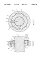
- FIG. 5 is a cross-sectional view thereof
- FIG. 6 is a side sectional view thereof
- FIG. 7 is a cross-sectional view showing another embodiment of the present invention which includes a bow-like latch spring
- FIG. 8 is a side sectional view according to FIG. 7;
- FIG. 9 is a perspective exploded view of still another embodiment of the present invention which includes a U-shaped latch spring
- FIG. 10 is a cross-sectional view according to FIG. 9;
- FIG. 11 is a perspective exploded view of still another embodiment of the present invention.
- FIG. 12 is a cross-sectional view according to FIG. 11.
- the numeral wheel locating device of the present invention includes a conventional lock body 1, several numeral wheels 2, notched wheels 3 and springs 5.
- FIGS. 4 to 6 On the inner periphery of the numeral wheel 2 are formed several recesses 21 and on the outer periphery of the notched wheel 3 are formed several projections 31 for engaging with the recesses 21 so as to set the lock code of the numeral wheel 2. Only when the numeral wheel 2 is rotated to the set lock code, is the lock body 1 unlocked.
- a locating channel 32 is formed on the surface of the notched wheel 3 and a latch spring 6 is disposed in the locating channel 32.
- the latch spring 6 is M-shaped, including two lateral shoulder portions 61 and a central V-shaped conic portion 62.
- the locating channel 32 is shaped corresponding to the latch spring 6 and is positioned axially slightly in front of the projections 31, whereby when the notched wheel 3 is fitted into the numeral wheel 2, the projecting shoulder portions 61 of the latch spring 6 and the projections 31 of the notched wheel 3 are all engaged with the recesses 21 of the numeral wheel 2.
- the central V-shaped conic portion 62 of the latch spring 6 is engaged with a flute 91 of a shaft 9 of the lock body 1 so as to lock the notched wheel 3 with the shaft 9, whereby when a user rotates the numeral wheel 2, by means of the engagement between the V-shaped conic portion 62 and the flute 91 of the shaft 9, the user can feel that each numeral is for one location.
- a pushing pin 7 is used to push the notched wheel 3 backward as shown by phantom line of FIG. 6 so as to disengage the projections 31 from the recesses 21 while keeping the shoulder portions 61 of the latch spring 6 resiliently engaged with the recesses 21 as shown in FIGS. 5 and 6.
- the notched wheel 3 is prevented from separating from the numeral wheel 2 and because the notched wheel 3 is still locked with the shaft 9, the notched wheel 3 will not rotate relative to the shaft 9.
- the projections 31 are disengaged from the recesses 21, the numeral wheel 2 can be rotated relative to the notched wheel 3 for resetting the lock code.
- the numeral wheel 2 is rotated and located on a stage by stage basis, that is, the user can clearly recognize the rotation and location of the numeral wheel 2.
- the shaft 9 can be designed with different shapes in cross-section.
- the cross-section of the shaft 9 can be hexagonal or octagonal to suit the V-shaped conic portion 62 of the M-shaped latch spring 6.
- the shape of the cross-section of the shaft 9 is not limited and all those which can cooperate with the conic portion 62 should be included in the scope of the present invention.
- FIGS. 7 and 8 show another embodiment of the present invention, wherein the latch spring 8 is substantially bow-like and the notched wheel 3 is formed with a radial locating tunnel 32' cooperating with the bow-like latch spring 8.
- the latch spring 8 has an upper projecting portion for resiliently engaging with the recess 21 of the numeral wheel 2 and a lower projecting portion for resiliently engaging with the flute 91 of the shaft 9 to achieve the same function as the forgoing M-shaped latch spring 6.
- FIGS. 9 and 10 show still another embodiment of the present invention, wherein the latch spring 10 is U-shaped, having two lateral shoulder portions 101 which engage with the recesses 21 of the numeral wheel 2 as the projections 31 do.
- a projecting fulcrum 103 is formed on the surface of the notched wheel 3 under a center of the latch spring 10 for supporting the same.
- fixing leaf springs 102 are disposed beside the notched wheel 3 for the spring 5 to abut against the leaf springs 102 so as to lock the notched wheel 3.
- the U-shaped latch spring 10 cooperates with the conventional leaf springs 102 to achieve the same function as the forgoing M-shaped latch spring 6.
- FIGS. 11 and 12 show still another embodiment of the present invention, wherein the latch spring 10' is substantially M-shaped, having two lateral shoulder portions 101' for engaging with the recesses 21 of the numeral wheel 2.
- the latch spring 10' is formed with a V-shaped fulcrum at the central portion which is supported on a central portion of a surface of the notched wheel 3.
- the fixing leaf springs 102 are disposed beside the notched wheel 3 for locking the same.
- the numeral wheel locating device of the present invention employs the resilient latch spring so that when resetting the lock code of the numeral lock, the numeral wheel is rotarily adjusted in position and located stage by stage without totally disengaging from the notched wheel. Therefore, the present invention not only avoids jumping of the numeral but also facilitates the operation and recognition of the numeral lock.
Landscapes
- Lock And Its Accessories (AREA)
Abstract
A locating device for a numeral wheel of a numeral lock, comprising a lock body, several numeral wheels, notched wheels and springs, wherein a locating channel is formed on a surface of the notched wheel in front of projections thereof and a latch spring is disposed in the locating channel. The latch spring has upward projecting portions, whereby when the notched wheel is fitted into the numeral wheel, the projecting portions of the latch spring and the projections of the notched wheel are all engaged with recesses of the numeral wheel. When it is desired to adjust or change a lock code, a pushing pin is used to push the notched wheel backward so as to disengage the projections from the recesses while keeping the projecting portions of the latch spring resiliently engaged with the recesses. Therefore, the numeral wheel can be rotarily adjusted and located without totally disengaging from the notched wheel so as to avoid poor location and jumping of the numeral wheel.
Description
The present invention relates to a locating device for a numeral wheel of a numeral lock, which enables the numeral wheel to be rotarily adjusted and located without totally disengaging from the notched wheel so as to avoid poor location and jumping of the numeral wheel.
A conventional numeral lock is shown in FIGS. 1 to 3. Several numeral wheels 2a are disposed on the surface of a lock body 1a. Only when the numeral wheels 2a are rotated and located in accordance with a preset lock code of the numeral wheels 2a, the lock body 1a can be unlocked. A spring 5a is used to abut against fixing leaf springs 6a with the protuberances 61a thereof engaged with a recessed edge 42a of a notched wheel 4a so as to create locating feeling during rotation. However, when the user wishes to reset the look code of the numeral wheels 2a, a pushing pin 3a is passed through a hole 11a of the lock body 1a into the interior thereof to push the notched wheel 4a fitted in the numeral wheel 2a. The notched wheel 4a has several projections 41a on the surface for engaging with the recesses formed on inner periphery of the numeral wheel 2a. Accordingly, the lock code can be reset by means of adjusting the engagement position between the projections 41a and the recesses 21a. As mentioned above, after the pushing pin 3a resiliently pushes the notched wheel 4a backward to make the projections 41a thereof disengage from the recesses 21a of the numeral wheel 2a, the numeral wheel 2a can be freely rotated and located at a desired position. Thereafter, the pushing pin 3a is removed from the notched wheel 4a and the notched wheel 4a is resiliently restored to its home position and again fitted into the numeral wheel 2a. Thereby, the lock code of the numeral wheel 2a is changed.
However, according to the above arrangements, after the pushing pin 3a pushes the notched wheel 4a and disengages the same from the numeral wheel 2a, the numeral wheel 2a becomes freely rotatable without any locating force. As a result, when rotating the first numeral wheel, the second one may be rotated therewith and when rotating the second numeral wheel, the third one may be rotated therewith. Therefore, after the user rotates the numeral wheel 2a to a new position and releases the notched wheel 4a, it is quite possible that the projections 41a of the notched wheel 4a are not aligned with the recesses 21a of the numeral wheel 2a to cause jumping of the numeral wheel and result in error of the reset lock code.
It is therefore a primary object of the present invention to provide a locating device for a numeral wheel of a numeral lock, wherein a locating channel is formed on a surface of the notched wheel in front of the projections thereof and a latch spring is disposed in the locating channel. The latch spring has upward projecting portions, whereby when the notched wheel is fitted into the numeral wheel, the projecting portions of the latch spring and the projections of the notched wheel are all engaged with the recesses of the numeral wheel. When it is desired to adjust or change a lock code, the pushing pin is used to push the notched wheel backward so as to disengage the projections from the recesses while keeping the projecting portions of the latch spring resiliently engaged with the recesses. Therefore, the numeral wheel can be rotarily adjusted and located without totally disengaging from the notched wheel and the projecting portions of the latch spring enable the user to perform the adjustment stage by stage. Therefore, after releasing the notched wheel, the lock code is accurately reset and the jumping of the numeral and difficulty in adjustment are eliminated.
The present invention can be best understood through the following description and accompanying drawing, wherein:
FIG. 1 is a perspective view of a conventional numeral lock;
FIG. 2 is a cross-sectional view of the conventional numeral lock;
FIG. 3 is a side sectional view of the conventional numeral lock;
FIG. 3A is a perspective exploded view of the conventional numeral lock;
FIG. 4 is a perspective exploded view of an embodiment of the present invention;
FIG. 5 is a cross-sectional view thereof;
FIG. 6 is a side sectional view thereof;
FIG. 7 is a cross-sectional view showing another embodiment of the present invention which includes a bow-like latch spring;
FIG. 8 is a side sectional view according to FIG. 7;
FIG. 9 is a perspective exploded view of still another embodiment of the present invention which includes a U-shaped latch spring;
FIG. 10 is a cross-sectional view according to FIG. 9;
FIG. 11 is a perspective exploded view of still another embodiment of the present invention; and
FIG. 12 is a cross-sectional view according to FIG. 11.
Please refer to FIG. 4. The numeral wheel locating device of the present invention includes a conventional lock body 1, several numeral wheels 2, notched wheels 3 and springs 5.
Please refer to FIGS. 4 to 6. On the inner periphery of the numeral wheel 2 are formed several recesses 21 and on the outer periphery of the notched wheel 3 are formed several projections 31 for engaging with the recesses 21 so as to set the lock code of the numeral wheel 2. Only when the numeral wheel 2 is rotated to the set lock code, is the lock body 1 unlocked.
In order to eliminate the problem of jumping of the numeral which occurs in the conventional device when resetting the lock code, a locating channel 32 is formed on the surface of the notched wheel 3 and a latch spring 6 is disposed in the locating channel 32. The latch spring 6 is M-shaped, including two lateral shoulder portions 61 and a central V-shaped conic portion 62. The locating channel 32 is shaped corresponding to the latch spring 6 and is positioned axially slightly in front of the projections 31, whereby when the notched wheel 3 is fitted into the numeral wheel 2, the projecting shoulder portions 61 of the latch spring 6 and the projections 31 of the notched wheel 3 are all engaged with the recesses 21 of the numeral wheel 2. At this time, the central V-shaped conic portion 62 of the latch spring 6 is engaged with a flute 91 of a shaft 9 of the lock body 1 so as to lock the notched wheel 3 with the shaft 9, whereby when a user rotates the numeral wheel 2, by means of the engagement between the V-shaped conic portion 62 and the flute 91 of the shaft 9, the user can feel that each numeral is for one location. However, when it is desired to adjust or change the lock code, a pushing pin 7 is used to push the notched wheel 3 backward as shown by phantom line of FIG. 6 so as to disengage the projections 31 from the recesses 21 while keeping the shoulder portions 61 of the latch spring 6 resiliently engaged with the recesses 21 as shown in FIGS. 5 and 6. Therefore, by means of the resilient engagement between the shoulder portions 61 of the latch spring 6 and the recesses 21, the notched wheel 3 is prevented from separating from the numeral wheel 2 and because the notched wheel 3 is still locked with the shaft 9, the notched wheel 3 will not rotate relative to the shaft 9. However, since the projections 31 are disengaged from the recesses 21, the numeral wheel 2 can be rotated relative to the notched wheel 3 for resetting the lock code. At this time, by means of the resilient engagement between the shoulder portions 61 of the latch spring 6 and the recesses 21, the numeral wheel 2 is rotated and located on a stage by stage basis, that is, the user can clearly recognize the rotation and location of the numeral wheel 2. After adjusted, the notched wheel 3 is released and the projections 31 thereof can be accurately re-engaged with and located in the recesses 21 without jumping of the numeral or difficulty in operation. The shaft 9 can be designed with different shapes in cross-section. For example, the cross-section of the shaft 9 can be hexagonal or octagonal to suit the V-shaped conic portion 62 of the M-shaped latch spring 6. However, the shape of the cross-section of the shaft 9 is not limited and all those which can cooperate with the conic portion 62 should be included in the scope of the present invention.
Moreover, please refer to FIGS. 7 and 8 which show another embodiment of the present invention, wherein the latch spring 8 is substantially bow-like and the notched wheel 3 is formed with a radial locating tunnel 32' cooperating with the bow-like latch spring 8. The latch spring 8 has an upper projecting portion for resiliently engaging with the recess 21 of the numeral wheel 2 and a lower projecting portion for resiliently engaging with the flute 91 of the shaft 9 to achieve the same function as the forgoing M-shaped latch spring 6.
FIGS. 9 and 10 show still another embodiment of the present invention, wherein the latch spring 10 is U-shaped, having two lateral shoulder portions 101 which engage with the recesses 21 of the numeral wheel 2 as the projections 31 do. A projecting fulcrum 103 is formed on the surface of the notched wheel 3 under a center of the latch spring 10 for supporting the same. In order to securely lock the notched wheel 3 with the shaft 9, fixing leaf springs 102 are disposed beside the notched wheel 3 for the spring 5 to abut against the leaf springs 102 so as to lock the notched wheel 3. The U-shaped latch spring 10 cooperates with the conventional leaf springs 102 to achieve the same function as the forgoing M-shaped latch spring 6.
Finally, please refer to FIGS. 11 and 12 which show still another embodiment of the present invention, wherein the latch spring 10' is substantially M-shaped, having two lateral shoulder portions 101' for engaging with the recesses 21 of the numeral wheel 2. In addition, the latch spring 10' is formed with a V-shaped fulcrum at the central portion which is supported on a central portion of a surface of the notched wheel 3. Similar to the above mentioned embodiment, the fixing leaf springs 102 are disposed beside the notched wheel 3 for locking the same.
In conclusion, the numeral wheel locating device of the present invention employs the resilient latch spring so that when resetting the lock code of the numeral lock, the numeral wheel is rotarily adjusted in position and located stage by stage without totally disengaging from the notched wheel. Therefore, the present invention not only avoids jumping of the numeral but also facilitates the operation and recognition of the numeral lock.
It is to be understood that the above description and drawings are only used for illustrating one embodiment of the present invention, not intended to limit the scope thereof. Any variation and derivation from the above description and drawings should be included in the scope of the present invention.
Claims (3)
1. A locating device for a numeral wheel of a numeral lock, comprising:
a lock body,
a plurality of numeral wheels, notched wheels, and springs, wherein
on an inner periphery of each said numeral wheel are formed several recesses and on an outer periphery of each said notched wheel are formed several projections for engaging with said recesses,
a locating channel is formed on a surface of each said notched wheel and a latch spring is disposed in said locating channel, each said latch spring having upward projecting portions slightly protruding beyond said locating channel, each said notched wheel being locked with a shaft of said lock body, said locating channel being positioned axially slightly in front of said projecting portions, whereby
when each said notched wheel is fitted into a corresponding numeral wheel, said projecting portions of said latch spring and said projections of each said notched wheel are all engaged with said recesses of said corresponding numeral wheels and when it is desired to adjust or change a lock code, each said notched wheel is pushed backward so as to disengage said projections from said recesses while keeping said projecting portions of said latch spring resiliently engaged with said recesses, and wherein
said latch spring is M-shaped, including two lateral upward projecting portions and a central V-shaped downward projecting conic portion, said conic portion fits into a flute of said shaft of said lock body so as to lock each said notched wheel with said shaft.
2. The locating device as claimed in claim 1 wherein:
each said latch spring is U-shaped, having two lateral shoulder portions for engaging with said recesses of each said numeral wheel, a projecting fulcrum being formed on a surface of each said notched wheel under a center of each said latch spring for supporting each said latch spring, fixing leaf springs being disposed beside each said notched wheel for a corresponding latch spring to abut against said leaf springs so as to lock each said notched wheel.
3. The locating device as claimed in claim 1 wherein:
each said latch spring is substantially M-shaped, having two lateral shoulder portions for engaging with said recesses of each said numeral wheel and a central V-shaped fulcrum supported on a central portion of each said notched wheel, fixing leaf springs being disposed beside each said notched wheel for locking each said notched wheel.
Priority Applications (1)
| Application Number | Priority Date | Filing Date | Title |
|---|---|---|---|
| US08/395,953 US5653136A (en) | 1995-02-28 | 1995-02-28 | Locating device for numeral wheel of numeral lock |
Applications Claiming Priority (1)
| Application Number | Priority Date | Filing Date | Title |
|---|---|---|---|
| US08/395,953 US5653136A (en) | 1995-02-28 | 1995-02-28 | Locating device for numeral wheel of numeral lock |
Publications (1)
| Publication Number | Publication Date |
|---|---|
| US5653136A true US5653136A (en) | 1997-08-05 |
Family
ID=23565237
Family Applications (1)
| Application Number | Title | Priority Date | Filing Date |
|---|---|---|---|
| US08/395,953 Expired - Fee Related US5653136A (en) | 1995-02-28 | 1995-02-28 | Locating device for numeral wheel of numeral lock |
Country Status (1)
| Country | Link |
|---|---|
| US (1) | US5653136A (en) |
Cited By (18)
| Publication number | Priority date | Publication date | Assignee | Title |
|---|---|---|---|---|
| US5934120A (en) * | 1997-12-05 | 1999-08-10 | Kuo; Lambert | Lock with a resettable combination |
| US6062051A (en) * | 1993-09-18 | 2000-05-16 | Nam; Du Hyun | Dial lock slide for a slide fastener |
| US6209368B1 (en) * | 1999-09-08 | 2001-04-03 | Chin Tsun Lee | Combination lock |
| US20040079122A1 (en) * | 2002-10-24 | 2004-04-29 | Cheng-Che Tsai | Combination lock |
| US20060169007A1 (en) * | 2005-02-02 | 2006-08-03 | Staples The Office Superstore, Llc | Resettable lock |
| US20070220929A1 (en) * | 2006-03-21 | 2007-09-27 | Glyn Green | Lock |
| US20080060399A1 (en) * | 2006-09-13 | 2008-03-13 | Aba Ufo International Corp. | Method for reappearing combination of a combination lock and the structure thereof |
| US20090095034A1 (en) * | 2007-10-15 | 2009-04-16 | Acco Brands Usa, Llc | Security apparatus with reset mechanism |
| US20100307208A1 (en) * | 2009-06-04 | 2010-12-09 | Stampp W. Corbin | Locking pill bottle |
| US20110041574A1 (en) * | 2009-08-23 | 2011-02-24 | Kuo-Tsung Yang | Combination lock with dual key numbers |
| US7963132B2 (en) | 2005-11-18 | 2011-06-21 | Acco Brands Usa Llc | Locking device with passage |
| US7997106B2 (en) | 2009-05-29 | 2011-08-16 | Acco Brands Usa Llc | Security apparatus including locking head and attachment device |
| CN102199956A (en) * | 2010-03-24 | 2011-09-28 | 颜群 | Lock head with password dial plate |
| USD651889S1 (en) | 2011-04-19 | 2012-01-10 | Acco Brands Usa Llc | Security apparatus |
| US20130167599A1 (en) * | 2011-12-28 | 2013-07-04 | Meir Avganim | Combination lock with reduced axial length |
| US20160102475A1 (en) * | 2014-10-09 | 2016-04-14 | Lambert Kuo | Code-changeable assembly and dial wheel device |
| CN103835587B (en) * | 2013-11-27 | 2016-04-27 | 浙江中立集团有限公司 | A kind of cipher wheel assembly |
| US11286690B2 (en) * | 2017-07-07 | 2022-03-29 | Schlage Lock Company Llc | Combination lock |
Citations (18)
| Publication number | Priority date | Publication date | Assignee | Title |
|---|---|---|---|---|
| US730719A (en) * | 1903-02-09 | 1903-06-09 | Yale & Towne Mfg Co | Tumbler for combination-locks. |
| US1094735A (en) * | 1912-06-27 | 1914-04-28 | James B Mcchesney | Permutation-padlock. |
| US1240114A (en) * | 1915-07-16 | 1917-09-11 | Jacob Baum | Combination-lock. |
| US1313536A (en) * | 1919-08-19 | Combination-lock | ||
| US1410033A (en) * | 1921-12-28 | 1922-03-21 | Pass Arthur | Combination lock |
| AT89903B (en) * | 1921-10-31 | 1922-11-10 | Adolf Wejmelka | Combination lock. |
| US1497793A (en) * | 1922-11-16 | 1924-06-17 | John L Guerrant | Permutation lock |
| AT101612B (en) * | 1923-04-03 | 1925-11-10 | Jules Crets | Combination lock for safes, theft-proof rooms, etc. like |
| US1583688A (en) * | 1925-07-14 | 1926-05-04 | W H Keyless Lock Company Ltd | Keyless lock |
| US1924987A (en) * | 1932-10-17 | 1933-08-29 | Furino Antonio | Combination lock |
| US1928853A (en) * | 1932-03-04 | 1933-10-03 | William F Doenges | Tumbler for combination locks |
| US3473354A (en) * | 1968-05-31 | 1969-10-21 | Raven Ind Inc | Locking device |
| US4259856A (en) * | 1979-04-03 | 1981-04-07 | Presto Lock Company, Division Of Walter Kidde & Company, Inc. | Combination locks and dial-indexing spring therefor |
| US4312199A (en) * | 1980-05-22 | 1982-01-26 | La Gard Lock, Inc. | Combination lock tumbler wheel construction |
| US4445348A (en) * | 1980-07-30 | 1984-05-01 | Saikosha Works Ltd. | Combination lock |
| US4644767A (en) * | 1984-08-29 | 1987-02-24 | S.Franzen Sohne Gmbh & Co. | Permutation lock having rotary dials and a dial locking spring |
| US5027623A (en) * | 1990-10-15 | 1991-07-02 | Ling Chong Kuan | Combination lock having sensing means for dialing aid and anti-sensing means for security purpose |
| US5235831A (en) * | 1992-01-23 | 1993-08-17 | Robert E. Lauria | Combination lock having resetting feature |
-
1995
- 1995-02-28 US US08/395,953 patent/US5653136A/en not_active Expired - Fee Related
Patent Citations (18)
| Publication number | Priority date | Publication date | Assignee | Title |
|---|---|---|---|---|
| US1313536A (en) * | 1919-08-19 | Combination-lock | ||
| US730719A (en) * | 1903-02-09 | 1903-06-09 | Yale & Towne Mfg Co | Tumbler for combination-locks. |
| US1094735A (en) * | 1912-06-27 | 1914-04-28 | James B Mcchesney | Permutation-padlock. |
| US1240114A (en) * | 1915-07-16 | 1917-09-11 | Jacob Baum | Combination-lock. |
| AT89903B (en) * | 1921-10-31 | 1922-11-10 | Adolf Wejmelka | Combination lock. |
| US1410033A (en) * | 1921-12-28 | 1922-03-21 | Pass Arthur | Combination lock |
| US1497793A (en) * | 1922-11-16 | 1924-06-17 | John L Guerrant | Permutation lock |
| AT101612B (en) * | 1923-04-03 | 1925-11-10 | Jules Crets | Combination lock for safes, theft-proof rooms, etc. like |
| US1583688A (en) * | 1925-07-14 | 1926-05-04 | W H Keyless Lock Company Ltd | Keyless lock |
| US1928853A (en) * | 1932-03-04 | 1933-10-03 | William F Doenges | Tumbler for combination locks |
| US1924987A (en) * | 1932-10-17 | 1933-08-29 | Furino Antonio | Combination lock |
| US3473354A (en) * | 1968-05-31 | 1969-10-21 | Raven Ind Inc | Locking device |
| US4259856A (en) * | 1979-04-03 | 1981-04-07 | Presto Lock Company, Division Of Walter Kidde & Company, Inc. | Combination locks and dial-indexing spring therefor |
| US4312199A (en) * | 1980-05-22 | 1982-01-26 | La Gard Lock, Inc. | Combination lock tumbler wheel construction |
| US4445348A (en) * | 1980-07-30 | 1984-05-01 | Saikosha Works Ltd. | Combination lock |
| US4644767A (en) * | 1984-08-29 | 1987-02-24 | S.Franzen Sohne Gmbh & Co. | Permutation lock having rotary dials and a dial locking spring |
| US5027623A (en) * | 1990-10-15 | 1991-07-02 | Ling Chong Kuan | Combination lock having sensing means for dialing aid and anti-sensing means for security purpose |
| US5235831A (en) * | 1992-01-23 | 1993-08-17 | Robert E. Lauria | Combination lock having resetting feature |
Cited By (31)
| Publication number | Priority date | Publication date | Assignee | Title |
|---|---|---|---|---|
| US6062051A (en) * | 1993-09-18 | 2000-05-16 | Nam; Du Hyun | Dial lock slide for a slide fastener |
| US5934120A (en) * | 1997-12-05 | 1999-08-10 | Kuo; Lambert | Lock with a resettable combination |
| US6209368B1 (en) * | 1999-09-08 | 2001-04-03 | Chin Tsun Lee | Combination lock |
| US20040079122A1 (en) * | 2002-10-24 | 2004-04-29 | Cheng-Che Tsai | Combination lock |
| US6845643B2 (en) * | 2002-10-24 | 2005-01-25 | Cheng-Che Tsai | Combination lock |
| US20060169007A1 (en) * | 2005-02-02 | 2006-08-03 | Staples The Office Superstore, Llc | Resettable lock |
| US7963132B2 (en) | 2005-11-18 | 2011-06-21 | Acco Brands Usa Llc | Locking device with passage |
| US7775073B2 (en) | 2006-03-21 | 2010-08-17 | Henry Squire & Sons Limited | Lock |
| US20070220929A1 (en) * | 2006-03-21 | 2007-09-27 | Glyn Green | Lock |
| EP1837466A3 (en) * | 2006-03-21 | 2008-04-16 | Henry Squire & Sons Limited | Lock |
| US20080060399A1 (en) * | 2006-09-13 | 2008-03-13 | Aba Ufo International Corp. | Method for reappearing combination of a combination lock and the structure thereof |
| US7614266B2 (en) * | 2007-10-15 | 2009-11-10 | Acco Brands Usa Llc | Security apparatus with reset mechanism |
| US20090095034A1 (en) * | 2007-10-15 | 2009-04-16 | Acco Brands Usa, Llc | Security apparatus with reset mechanism |
| US7997106B2 (en) | 2009-05-29 | 2011-08-16 | Acco Brands Usa Llc | Security apparatus including locking head and attachment device |
| US8001812B2 (en) | 2009-05-29 | 2011-08-23 | Acco Brands Usa Llc | Security apparatus including locking head |
| US8042366B2 (en) | 2009-05-29 | 2011-10-25 | Acco Brands Usa Llc | Security apparatus including attachment device |
| US20100307208A1 (en) * | 2009-06-04 | 2010-12-09 | Stampp W. Corbin | Locking pill bottle |
| US8020415B2 (en) * | 2009-06-04 | 2011-09-20 | Stampp W. Corbin | Locking pill bottle |
| US20110041574A1 (en) * | 2009-08-23 | 2011-02-24 | Kuo-Tsung Yang | Combination lock with dual key numbers |
| CN102199956A (en) * | 2010-03-24 | 2011-09-28 | 颜群 | Lock head with password dial plate |
| USD660682S1 (en) | 2011-04-19 | 2012-05-29 | Acco Brands Usa Llc | Security apparatus |
| USD651889S1 (en) | 2011-04-19 | 2012-01-10 | Acco Brands Usa Llc | Security apparatus |
| USD661975S1 (en) | 2011-04-19 | 2012-06-19 | ACCO Brands Corporation | Attachment device for security apparatus |
| USD670553S1 (en) | 2011-04-19 | 2012-11-13 | ACCO Brands Corporation | Attachment device for security apparatus |
| US20130167599A1 (en) * | 2011-12-28 | 2013-07-04 | Meir Avganim | Combination lock with reduced axial length |
| US8739583B2 (en) * | 2011-12-28 | 2014-06-03 | Meir Avganim | Combination lock with reduced axial length |
| CN103835587B (en) * | 2013-11-27 | 2016-04-27 | 浙江中立集团有限公司 | A kind of cipher wheel assembly |
| US20160102475A1 (en) * | 2014-10-09 | 2016-04-14 | Lambert Kuo | Code-changeable assembly and dial wheel device |
| US9562369B2 (en) * | 2014-10-09 | 2017-02-07 | Lambert Kuo | Code-changeable assembly and dial wheel device |
| US11286690B2 (en) * | 2017-07-07 | 2022-03-29 | Schlage Lock Company Llc | Combination lock |
| US12077986B2 (en) | 2017-07-07 | 2024-09-03 | Schlage Lock Company Llc | Combination lock |
Similar Documents
| Publication | Publication Date | Title |
|---|---|---|
| US5653136A (en) | Locating device for numeral wheel of numeral lock | |
| US6334346B1 (en) | Numeral lock with resettable feature | |
| US6209368B1 (en) | Combination lock | |
| US5765417A (en) | Free wheel lock cylinder | |
| US5520032A (en) | Combination padlock with read-out windows | |
| US6557220B1 (en) | Security clutch with self-centering spring | |
| US6032777A (en) | Locking device, in particular for a motor vehicle seat | |
| TWI524857B (en) | Mother press and buckle | |
| US4866792A (en) | Shield mounting assembly for a safety helmet | |
| US5727850A (en) | Safety and control system for the locking mechanism of a wheel hub, notably for wheelchairs | |
| US4557122A (en) | Combined combination and key-type lock | |
| US20020190559A1 (en) | Adjustable chair seat with locking mechanism | |
| US2005792A (en) | Bezel mounting | |
| GB2223467A (en) | Lockable steering wheel deactivating mechanism | |
| EP3649306A1 (en) | Combination lock | |
| JPH0870912A (en) | Buckle device for infant restraining/protecting sheet | |
| US6012309A (en) | Pad lock with reliable change of code number | |
| GB2063988A (en) | Combination lock | |
| US6735825B1 (en) | Secured pen and holder | |
| US5839301A (en) | Combination lock | |
| US6470717B1 (en) | Dials of a combination padlock | |
| US5449228A (en) | Apparatus for locking an operating unit to a vehicle-mounted electronic equipment | |
| JPH0630517A (en) | Floor receptacle | |
| US4344063A (en) | Click setting variable resistor | |
| JP2579076Y2 (en) | Push-button bicycle lock that allows you to set a password |
Legal Events
| Date | Code | Title | Description |
|---|---|---|---|
| FPAY | Fee payment |
Year of fee payment: 4 |
|
| REMI | Maintenance fee reminder mailed | ||
| FPAY | Fee payment |
Year of fee payment: 8 |
|
| SULP | Surcharge for late payment |
Year of fee payment: 7 |
|
| REMI | Maintenance fee reminder mailed | ||
| LAPS | Lapse for failure to pay maintenance fees | ||
| STCH | Information on status: patent discontinuation |
Free format text: PATENT EXPIRED DUE TO NONPAYMENT OF MAINTENANCE FEES UNDER 37 CFR 1.362 |
|
| FP | Lapsed due to failure to pay maintenance fee |
Effective date: 20090805 |