US5604322A - Automatic performance apparatus with a display device - Google Patents
Automatic performance apparatus with a display device Download PDFInfo
- Publication number
- US5604322A US5604322A US08/413,355 US41335595A US5604322A US 5604322 A US5604322 A US 5604322A US 41335595 A US41335595 A US 41335595A US 5604322 A US5604322 A US 5604322A
- Authority
- US
- United States
- Prior art keywords
- parts
- designated
- performance state
- performance
- automatic
- Prior art date
- Legal status (The legal status is an assumption and is not a legal conclusion. Google has not performed a legal analysis and makes no representation as to the accuracy of the status listed.)
- Expired - Lifetime
Links
Images


Classifications
-
- G—PHYSICS
- G09—EDUCATION; CRYPTOGRAPHY; DISPLAY; ADVERTISING; SEALS
- G09B—EDUCATIONAL OR DEMONSTRATION APPLIANCES; APPLIANCES FOR TEACHING, OR COMMUNICATING WITH, THE BLIND, DEAF OR MUTE; MODELS; PLANETARIA; GLOBES; MAPS; DIAGRAMS
- G09B15/00—Teaching music
- G09B15/001—Boards or like means for providing an indication of chords
-
- G—PHYSICS
- G09—EDUCATION; CRYPTOGRAPHY; DISPLAY; ADVERTISING; SEALS
- G09B—EDUCATIONAL OR DEMONSTRATION APPLIANCES; APPLIANCES FOR TEACHING, OR COMMUNICATING WITH, THE BLIND, DEAF OR MUTE; MODELS; PLANETARIA; GLOBES; MAPS; DIAGRAMS
- G09B15/00—Teaching music
- G09B15/02—Boards or like means for providing an indication of notes
- G09B15/04—Boards or like means for providing an indication of notes with sound emitters
Definitions
- the present invention relates to an automatic performing apparatus of an electronic musical instrument that is capable of automatically performing a plurality of parts, and in particular embodiments to an automatic performing apparatus that is capable of bringing desired parts in the automatic performance into a non-performing state.
- an automatic performing apparatus that simultaneously performs a plurality of parts, and is capable of muting some of the parts.
- a performing apparatus is equipped with switches each for designating a performing state or a non-performing state of each of the parts.
- the switches are manipulated to bring designated parts into the non-performing state or into the performing state.
- the automatic performance apparatus may have display elements such as LEDs provided for the corresponding switches.
- Each of the LEDs indicates either an ON or an OFF state for each of the switches to thereby indicate either the performing state or the non-performing state of each of the parts.
- the performing state or the non-performing state of each part can be recognized by the ON or OFF state Of each of the switches, the performance content of each of the parts is not provided by the ON or OFF state of the switch.
- the automatic performance apparatus also includes a designating device for designating a part in the score being displayed on the display device, a performance controlling device, responsive to the designating device, for controlling the performing device to bring the part designated into a non-performance state, and a display controlling device, responsive to the designating device, for controlling the display device to display the non-performance state of the designated part.
- performance data for a plurality of parts is retrieved for the automatic performance of the plurality of parts, and a musical score representing the plurality of parts is displayed on a display device. Furthermore, a particular part in the musical score may be selected on the display device to bring the particular part into a non-performance state.
- a particular part in the musical score may be selected on the display device to bring the particular part into a non-performance state.
- the non-performance state of the particular part is indicated on the display device, but the content of the particular part in the non-performance state may be indicated on the display device.
- FIG. 1 is a schematic block diagram of a hardware configuration in accordance with an embodiment of the present invention.
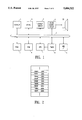
- FIG. 2 shows a memory format of automatic performance data in accordance with an embodiment of the present invention.
- FIG. 3 shows a score in the performance state displayed on a display device in accordance with an embodiment of the present invention.
- FIG. 4 shows a score with one part in the non-performance state in accordance with an embodiment of the present invention.
- FIG. 5 is a flow chart of a main routine process in accordance with an embodiment of the present invention.
- FIG. 6 is a flow chart of a mouse click process in accordance with an embodiment of the present invention.
- FIG. 7 is a flow chart of a timer interrupt process in accordance with an embodiment of the present invention.
- FIG. 1 is a schematic block diagram of a hard ware configuration.
- a CPU 1 controls the overall operation of the apparatus, and executes processes in accordance with a control program stored in a ROM 3.
- the CPU 1 and respective elements are connected to each other through a bus 2 for transmission and reception of various data.
- a RAM 4 is provided with work areas, such as registers and flags, for temporarily storing various data generated during the processes executed by the CPU 1.
- the RAM 4 is also provided with work areas for storing image data of a score read by a scanner 5 (which will be described later) and automatic performance data.
- the automatic performance data may be generated by image-processing the score image data read by the scanner 5 and by recognizing the content of the score.
- a timer 9 provides an interrupt signal to the CPU 1 at a variable cycle corresponding to a specific tempo. For example, at a cycle at which 96 signals are generated per a quarter note, or in other words, at a cycle equal to a three hundred eighty fourth note.
- the CPU 1 in response to the generation of the interrupt signal, reads out automatic performance data stored in the RAM 4 to carry out the automatic performance at a particular tempo.
- the CPU 1 generates note data, such as, note-on, note-off or the like, based on the retrieved automatic performance data, and provides the note data through the bus 2 to a sound source circuit 8.
- the sound source circuit 8 generates a musical note waveshape signal according to the inputted note data and a musical note control data.
- the apparatus may use a sound source system, such as, a well-known waveshape memory read out system, an FM (frequency modulation) system, a physical model simulation system or the like.
- the musical note waveshape signal formed at the sound source circuit 8 is provided to a sound system 11 where a musical sound is generated.
- the scanner 5 reads a score from a printed score or the like, and produces a score image data.
- the score image data is stored in a score image memory region provided in the RAM 4.
- Automatic performance data is generated by the score recognition process based on the stored score image data.
- the score recognition process utilizes well known techniques. Therefore, only a brief description of the score recognition process is provided, and its detailed description is omitted.
- Five lines are extracted from the obtained score image data and the location of the five lines and other features are detected. Then, the five lines are erased from the score image data.
- Various notes and signs are then extracted from the remaining score image during the recognition of the notes and the signs. Note pitches of the recognized notes are determined based on the location of the previously detected five lines.
- Automatic performance data is generated based on the determined note pitches and types of the recognized notes. In addition, a variety of other signs (G clef, F clef, meter, accidental marks such as sharp and flat) are considered to complete the generation of the automatic performance data.
- the reference numeral 7 denotes a display device, such as an LCD for displaying the score image read by the scanner 5 and the automatic performance data obtained by the note recognition process.
- the display device 7 is also adapted for displaying a menu and switches for executing various functions of the automatic performance apparatus.
- the reference numeral 6 denotes a position indicating device, such as a mouse, track ball or the like for indicating and selecting particular menu items and switches to execute a variety of functions. The movement and the click operation of the mouse 6 are detected by the CPU 1.
- the reference numeral 10 denotes a MIDI interface (I/F), for transmission and reception of MIDI data with an external electronic musical instrument.
- the MIDI interface 10 provides the note event data and other data generated by the automatic performance process to an external sound source apparatus.
- FIG. 2 shows a memory format of automatic performance data generated in the manner described above.
- the automatic performance data includes event data representing various kinds of note events to be generated (e.g., key on/off, pitch and dynamics) and timing data representing timing of the event data generation.
- the timing data represents the number of clocks to be generated for a separation between two adjacent event data, each clock having a unit time length corresponding to the timer interrupt cycle as described above.
- the automatic performance data also includes data regarding bar lines, and data concerning loudness and pitch bend.
- the automatic performance data in this memory format are stored in a number of locations corresponding to the number of the performance parts.
- timing data and event data of the automatic performance data for each of the plurality of the parts are read out in parallel with each other to carry out the automatic performance of the plurality of the parts.
- the memory format of the automatic performance data shown is one example. However, in alternative embodiments, other formats may be used to store the automatic performance data.
- FIGS. 3 and 4 show one example of the content displayed by means of the display device 7.
- a window W1 is used to edit the automatic performance data obtained by the musical score recognition process as described above. Notes which are erroneously recognized and are different from the original notes can be corrected in the displayed score.
- a menu M is used to execute a variety of commandable functions by manipulating the mouse 6 on the window W1. The manipulation position of the mouse 6 is indicated by a cursor C. The indicated position of the cursor C changes in accordance with the movement of the mouse 6. The cursor C may be moved over to the menu M.
- Function switches SW are provided below the menu M.
- the cursor C may be moved over to the function switches SW, and the switch of the mouse 6 is clicked with the cursor C positioned on one of the function switches to execute a function associated with the selected function switch.
- a play switch SW1 commands the start of the automatic performance.
- a stop switch SW2 commands the stop of the automatic performance.
- the automatic performance is stopped.
- the cursor C may also be moved over to a position in the score being displayed, and the switch of the mouse 6 is then clicked with the cursor at this position to display a pop-up menu concerning musical notes.
- the pop-up menu allows the user to edit the score, such as correction, addition and deletion of notes.
- the automatic performance data can be corrected.
- the automatic performance can be heard by clicking the switch SW1, as described above.
- the plurality of performance parts may also be played simultaneously.
- the plurality of performance parts may be played while only the edit window W1 is displayed.
- the entire score viewing window W2 is opened by executing an open command switch that may be located in a predetermined function list in the menu M.
- the entire score viewing window W2 displays the entire score that has been inputted. In the illustrated embodiment, a score consisting of four parts, part 1 (P1) to part 4 (P4), is displayed.
- the entire score viewing window W2 displays a frame F representing an area of the score displayed in the edit window W1 and a location pointer L that indicates the location of the current progression of the automatic performance.
- a frame F representing an area of the score displayed in the edit window W1
- a location pointer L that indicates the location of the current progression of the automatic performance.
- the cursor C may be moved to a location in the score of a desired part that is displayed in the entire score viewing window W2, and then the switch of the mouse 6 is clicked with the cursor C being positioned at this location to set the part into the non-performance state.
- the non-performance state is displayed in a manner as shown in FIG. 4.
- the illustrated embodiment shows an occasion in which the mouse is clicked with the cursor C being located over the part 3 (P3).
- the position of the score representing the part 3 is covered with a hatching to indicate that the part 3 is in the non-performance state.
- the non-performance state may be indicated by other appropriate methods.
- the score may be covered by a hatching that still thinly shows the score through the hatching, or the color of the score may be changed without using a hatching.
- the part When the switch of the mouse 6 is clicked with the cursor C positioned over the hatching of the part that is in the non-performance state, the part is set back to the performance state.
- the display is set back to the original state that displays the score for that part.
- the mouse 6 may be clicked on another part to also set that part into the non-performance state. Namely, each part may be brought into the performance state or the non-performance state independently of other parts. Also, all of the parts can be switched into the non-performance state together. In this manner, the switch of the mouse 6 is clicked with the cursor C being located on the parts displayed in the entire score viewing window W2 to bring them into the non-performance state or the performance state.
- the parts in the non-performance state are displayed differently from the parts in the performance state. As a result, the performance contents of the parts in the non-performance state are readily recognized.
- the non-performance state of a score is preferably displayed by a hatching that still thinly shows the score through the hatching or by a different color so that the performance content of the part in the non-performance state can be readily recognized
- FIG. 5 shows a main routine.
- an initialization process such as clearing the RAM 4 is carried out in step S1.
- the process proceeds to step S2 where a determination is made as to whether the mouse 6 has been moved. If the mouse has been moved, a process concerning the operation of the mouse, such as, moving the displayed cursor C, or the like in step S3 is executed. If the determination is made in step S2 that the mouse has not been moved, the process advances to step S4 where a determination is made as to whether the switch of the mouse 6 has been clicked.
- step S5 a mouse click process is executed. Thereafter, in step S6, other processes are executed. If the determination is made in step S4 that there has not been a click of the switch of the mouse 6, the process proceeds to step S6 where other processes are executed.
- the other processes include a process for transmission and reception of MIDI data through the MIDI interface 10.
- step S5 A determination is made in step S11 as to whether the switch on the mouse 6 is clicked with the cursor C being located in the entire score viewing window W2. When the determination is “Yes” the process proceeds to step S17. When the determination is "No”, the process proceeds to step S12. More particularly, when the switch of the mouse 6 is clicked with the cursor C being located outside of the entire score viewing window W2, the determination in step 11 is "No” and the process proceeds to step S12. In step S12, a determination is made as to whether the mouse 6 is clicked with the cursor C being positioned on the display switch SW1. If the determination in step S12 is "Yes” a process of starting the automatic performance is executed in step S13.
- step S12 determines whether the mouse 6 is clicked with the cursor C being positioned on the stop switch SW2. If the determination is "Yes”, the process proceeds to step S15 where a process of stopping the automatic performance is executed.
- the process of stopping the automatic performance is also well known, and therefore the description for such a process is omitted.
- step S16 When the determination is "No" in step 14, the mouse 6 has been clicked at other switches, on the menu M or on the displayed score in the edit window W1, and thus the process proceeds to step S16.
- step S16 other processes, corresponding to the location of the cursor C at which the mouse 6 is clicked, is executed to complete the mouse click process.
- the mouse click process is completed in a similar manner after step S13 and step S15.
- step S11 determines whether the mouse 6 has been clicked at a location on the score representing part 1. If “Yes”, the process proceeds to step S18 to switch part 1 between the performance state and the non-performance state, in which a flag MUTE 1 representing either the performance state or the non-performance state of part 1 is reversed. When the flag MUTE 1 has a value of 1, the process proceeds to step S20 where part 1 is muted (e.g., shown covered with the hatching in the illustrated embodiment in FIG. 4), and then the process returns to the main routine.
- part 1 is muted (e.g., shown covered with the hatching in the illustrated embodiment in FIG. 4), and then the process returns to the main routine.
- step S19 determines whether the determination in step S19 is "No" or "No" the process proceeds to step S21 where the display indicating the muted part 1 is released (and the hatching is removed), and the process returns to the main routine.
- step S21 the display indicating the muted part 1 is released (and the hatching is removed), and the process returns to the main routine.
- the switch of the mouse 6 is clicked with the cursor C being located on part 1, part 1 is switched alternatively between the performance state and the non-performance state.
- the score of part 1 is covered by the hatching to indicate the non-performance state.
- step S17 When the determination in step S17 is "No", a determination is made in step S22 as to whether the mouse 6 is clicked on part 2. If “Yes”, part 2 is muted in step S23 (in the same manner as the above described steps S18 through step S21 for the part 1).
- step S23 In the same manner as the above described steps S18 through step S21 for the part 4, the process proceeds to steps S24 and S25 and steps S26 and S27, respectively, where part 3 and part 4 are muted, respectively.
- an interrupt cycle is executed by interrupting the main routine each time the timer 9 generates an interrupt signal for the CPU 1.
- an interrupt cycle may be defined by a time duration equal to a three hundred eighty fourth note, as described above, and is variable depending upon a specified tempo.
- step S31 a determination is made in step S31 as to whether the automatic performance is currently progressing.
- the timer interrupt process is executed after the process of starting the automatic performance is executed in step S13, the determination is "Yes”.
- the timer interrupt process is executed before the process of starting the automatic performance is executed in step S13, or after the automatic performance has been started but the process of stopping the automatic performance is executed, the determination is "No".
- the determination is "No" the timer interrupt process is immediately finished.
- step S32 If the determination in step S31 is "Yes", the value of register TIME 1 is decremented in step S32.
- the timing data described above (see FIG. 2) is set in the register TIME 1, and the value of the timing data is decremented each time the timer interrupt process is executed.
- the register TIME 1 controls the timing of the generation of event data in part 1.
- An initial value of the register TIME 1 is set in the automatic performance starting process in step S13.
- step S33 a determination is made in step S33 as to whether the value of the register TIME 1 is zero (0). If “Yes” the time indicated by the timing data has elapsed, and the process has reached a timing at which the event data should be generated. Therefore, the next data, namely, data stored at an address next to the timing data is read out in step S34. A determination is made in step S35 as to whether the read out date is timing data. The determination is "No" because event data is stored next to the timing data in the illustrated embodiment.
- step S36 a determination is made as to whether the read out data is event data. If "Yes”, a determination is made in step S37 as to whether the abovementioned flag MUTE 1 has the value of "1" or "0". In other words, a determination is made as to whether part 1 is in the performance state. If “Yes”, the data read out in step S38 is outputted through the MIDI interface 10 to an external sound source apparatus. If the determination in step S37 is "No", part 1 is in the non-performance state, and the read out data is not outputted to the external sound source apparatus. Thereafter, the process returns to step S34.
- step S36 determines whether the read out data is neither timing data nor event data. In this case, the process proceeds to step S39, where a process representative of the read out data is executed. For example, if the read out data is data for changing the loudness, the loudness change data is outputted to the sound source circuit 8. If the read out data is data for the management of bars, a process for managing the bars is executed. Thereafter, the process returns to step S34.
- step S34 data at the next address is read out as described above. This time, the data is the one stored next to event data, and there is a possibility that the read out data is timing data. If the read out data is timing data, the determination in step S35 is "Yes" and the process proceeds to step S40. In step S40, the read out timing data is stored in the register TIME 1, for the preparation of reading out the next event data.
- Processes of reading out parts 2, 3 and 4 are executed in a similar manner as the process executed for part 1 (in step S41, step S42 and step S43), then the displayed location pointer L is moved in the direction of the performance progression, and the timer interrupt process is completed.
- performance data for parts 1 through 4 are read out. If the flag MUTE 1 for any one of the parts has the value "1", note event data for that part is not outputted to the sound source circuit since that part is in the non-performance state.
- an automatic performance apparatus has a sound source circuit.
- the sound source circuit may be provided independently of the apparatus.
- an automatic performance apparatus in accordance with an embodiment of the present invention may be composed of a personal computer and an application software.
- a mouse is used to designate a part to be placed in the non-performance state or in the performance state.
- other devices such as, for example, a track ball may be used to designate a part.
- a touch panel may be provided at the display device so that a user directly touches the displayed score to execute various commands.
- the read out performance data for a part is not outputted to the sound source circuit when the part is in the non-performance state.
- commands may be provided to the sound source circuit so that the loudness is reduced to "0" or substantially "0".
- an automatic performance data is formed by reading a score image by a scanner and by processing the score image by a score recognition process.
- the performance data may be formed, using the conventional key board.
- the performance data may be formed by the use of switches to designate the tone pitch and tone length.
- a separate memory device (not shown), or an additional work area in the RAM 4 may be provided for storing data that is different from the performance data.
- the separate memory device stores image data that is used for displaying bit map images on the display device 7.
- a score image representing the performance data and another image representing the data stored in the separate memory device may be simultaneously displayed on the display device 7.
- only an image representing the data stored in the separate memroy device may be displayed while the score image based on the performance data is not displayed.
Abstract
An automatic performance apparatus with an improved non-performance state display device. The automatic performance apparatus includes a memory device for storing automatic performance data for a plurality of parts, a performing device for reading out the automatic performance data for a plurality of part and performing a plurality of parts, and a display device for displaying a score of a plurality of parts based on the automatic performance data read out. It also includes a designating device for designating a part in the score being displayed on the display means, a performance controlling device responsive to the designating device for controlling the performing device to set the part designated in a non-performance state, and a display controlling device responsive to designation of the designating device for controlling the display device to display that the designated part is in the non-performance state.
Description
1. Field of the Invention
The present invention relates to an automatic performing apparatus of an electronic musical instrument that is capable of automatically performing a plurality of parts, and in particular embodiments to an automatic performing apparatus that is capable of bringing desired parts in the automatic performance into a non-performing state.
2. Description of Related Art
There has been an automatic performing apparatus that simultaneously performs a plurality of parts, and is capable of muting some of the parts. Typically, such a performing apparatus is equipped with switches each for designating a performing state or a non-performing state of each of the parts. The switches are manipulated to bring designated parts into the non-performing state or into the performing state. Also, the automatic performance apparatus may have display elements such as LEDs provided for the corresponding switches. Each of the LEDs indicates either an ON or an OFF state for each of the switches to thereby indicate either the performing state or the non-performing state of each of the parts. However, although the performing state or the non-performing state of each part can be recognized by the ON or OFF state Of each of the switches, the performance content of each of the parts is not provided by the ON or OFF state of the switch.
It is an object of embodiments of the present invention to provide an automatic performance apparatus which is capable of simultaneously performing a plurality of parts and also capable of indicating the performance content of the parts, regardless of whether they are in the performance state or the non-performance state.
It is another object of embodiments of the present invention to provide an automatic performance apparatus having a memory device for storing automatic performance data for a plurality of parts, a performing device for reading out the automatic performance data for a plurality of parts and performing a plurality of parts, and a display device for displaying a score of a plurality of parts based on the read out automatic performance data. The automatic performance apparatus also includes a designating device for designating a part in the score being displayed on the display device, a performance controlling device, responsive to the designating device, for controlling the performing device to bring the part designated into a non-performance state, and a display controlling device, responsive to the designating device, for controlling the display device to display the non-performance state of the designated part.
In accordance with the above-mentioned configuration, performance data for a plurality of parts is retrieved for the automatic performance of the plurality of parts, and a musical score representing the plurality of parts is displayed on a display device. Furthermore, a particular part in the musical score may be selected on the display device to bring the particular part into a non-performance state. In accordance with embodiments of the present invention, not only the non-performance state of the particular part is indicated on the display device, but the content of the particular part in the non-performance state may be indicated on the display device.
Other features and advantages of the invention will be apparent from the following detailed description, taken in conjunction with the accompanying drawings which illustrate, by way of example, various features of embodiments of the invention.
FIG. 1 is a schematic block diagram of a hardware configuration in accordance with an embodiment of the present invention.
FIG. 2 shows a memory format of automatic performance data in accordance with an embodiment of the present invention.
FIG. 3 shows a score in the performance state displayed on a display device in accordance with an embodiment of the present invention.
FIG. 4 shows a score with one part in the non-performance state in accordance with an embodiment of the present invention.
FIG. 5 is a flow chart of a main routine process in accordance with an embodiment of the present invention.
FIG. 6 is a flow chart of a mouse click process in accordance with an embodiment of the present invention.
FIG. 7 is a flow chart of a timer interrupt process in accordance with an embodiment of the present invention.
An embodiment of the present invention is described below with reference to the accompanying drawings. FIG. 1 is a schematic block diagram of a hard ware configuration. A CPU 1 controls the overall operation of the apparatus, and executes processes in accordance with a control program stored in a ROM 3. The CPU 1 and respective elements are connected to each other through a bus 2 for transmission and reception of various data. A RAM 4 is provided with work areas, such as registers and flags, for temporarily storing various data generated during the processes executed by the CPU 1. The RAM 4 is also provided with work areas for storing image data of a score read by a scanner 5 (which will be described later) and automatic performance data. In one embodiment, the automatic performance data may be generated by image-processing the score image data read by the scanner 5 and by recognizing the content of the score. A timer 9 provides an interrupt signal to the CPU 1 at a variable cycle corresponding to a specific tempo. For example, at a cycle at which 96 signals are generated per a quarter note, or in other words, at a cycle equal to a three hundred eighty fourth note. The CPU 1, in response to the generation of the interrupt signal, reads out automatic performance data stored in the RAM 4 to carry out the automatic performance at a particular tempo.
The CPU 1 generates note data, such as, note-on, note-off or the like, based on the retrieved automatic performance data, and provides the note data through the bus 2 to a sound source circuit 8. The sound source circuit 8 generates a musical note waveshape signal according to the inputted note data and a musical note control data. The apparatus may use a sound source system, such as, a well-known waveshape memory read out system, an FM (frequency modulation) system, a physical model simulation system or the like. The musical note waveshape signal formed at the sound source circuit 8 is provided to a sound system 11 where a musical sound is generated.
The scanner 5 reads a score from a printed score or the like, and produces a score image data. The score image data is stored in a score image memory region provided in the RAM 4. Automatic performance data is generated by the score recognition process based on the stored score image data. The score recognition process utilizes well known techniques. Therefore, only a brief description of the score recognition process is provided, and its detailed description is omitted. Five lines are extracted from the obtained score image data and the location of the five lines and other features are detected. Then, the five lines are erased from the score image data. Various notes and signs are then extracted from the remaining score image during the recognition of the notes and the signs. Note pitches of the recognized notes are determined based on the location of the previously detected five lines. Automatic performance data is generated based on the determined note pitches and types of the recognized notes. In addition, a variety of other signs (G clef, F clef, meter, accidental marks such as sharp and flat) are considered to complete the generation of the automatic performance data.
The reference numeral 7 denotes a display device, such as an LCD for displaying the score image read by the scanner 5 and the automatic performance data obtained by the note recognition process. The display device 7 is also adapted for displaying a menu and switches for executing various functions of the automatic performance apparatus. The reference numeral 6 denotes a position indicating device, such as a mouse, track ball or the like for indicating and selecting particular menu items and switches to execute a variety of functions. The movement and the click operation of the mouse 6 are detected by the CPU 1.
The reference numeral 10 denotes a MIDI interface (I/F), for transmission and reception of MIDI data with an external electronic musical instrument. The MIDI interface 10 provides the note event data and other data generated by the automatic performance process to an external sound source apparatus.
FIG. 2 shows a memory format of automatic performance data generated in the manner described above. The automatic performance data includes event data representing various kinds of note events to be generated (e.g., key on/off, pitch and dynamics) and timing data representing timing of the event data generation. The timing data represents the number of clocks to be generated for a separation between two adjacent event data, each clock having a unit time length corresponding to the timer interrupt cycle as described above. The automatic performance data also includes data regarding bar lines, and data concerning loudness and pitch bend. When the inputted score consists of a plurality of performance parts, the automatic performance data in this memory format are stored in a number of locations corresponding to the number of the performance parts. In the automatic performance, timing data and event data of the automatic performance data for each of the plurality of the parts are read out in parallel with each other to carry out the automatic performance of the plurality of the parts. The memory format of the automatic performance data shown is one example. However, in alternative embodiments, other formats may be used to store the automatic performance data.
FIGS. 3 and 4 show one example of the content displayed by means of the display device 7. In FIG. 3, a window W1 is used to edit the automatic performance data obtained by the musical score recognition process as described above. Notes which are erroneously recognized and are different from the original notes can be corrected in the displayed score. A menu M is used to execute a variety of commandable functions by manipulating the mouse 6 on the window W1. The manipulation position of the mouse 6 is indicated by a cursor C. The indicated position of the cursor C changes in accordance with the movement of the mouse 6. The cursor C may be moved over to the menu M. Clicking the switch of the mouse 6 with the cursor C placed on one of the words displayed in the window W1, such as, File, Edit and Windows in the menu, displays a list containing a plurality of available function commands relating to the selected word. One of the function commands is selected from the displayed list, and the switch of the mouse 6 is clicked with the cursor placed at the selected function command to execute a function corresponding to the selected function command.
Function switches SW are provided below the menu M. The cursor C may be moved over to the function switches SW, and the switch of the mouse 6 is clicked with the cursor C positioned on one of the function switches to execute a function associated with the selected function switch. For example, a play switch SW1 commands the start of the automatic performance. By a click of the switch on the mouse 6 with the cursor C positioned at the switch SW1, the automatic performance is started. A stop switch SW2 commands the stop of the automatic performance. By a click of the mouse 6 at the switch SW2, the automatic performance is stopped.
The cursor C may also be moved over to a position in the score being displayed, and the switch of the mouse 6 is then clicked with the cursor at this position to display a pop-up menu concerning musical notes. The pop-up menu allows the user to edit the score, such as correction, addition and deletion of notes. By editing the musical score being displayed, the automatic performance data can be corrected. When a correction has been made, the automatic performance can be heard by clicking the switch SW1, as described above.
In accordance with an embodiment of the present invention, when the recognized musical score includes a plurality of performance parts, the plurality of performance parts may also be played simultaneously. The plurality of performance parts may be played while only the edit window W1 is displayed. However, it is easier to see the overall performance of the plurality of parts when an entire score viewing window W2 is displayed. Although a detailed description for the entire score viewing window W2 is omitted, in a preferred embodiment, the entire score viewing window W2 is opened by executing an open command switch that may be located in a predetermined function list in the menu M. The entire score viewing window W2 displays the entire score that has been inputted. In the illustrated embodiment, a score consisting of four parts, part 1 (P1) to part 4 (P4), is displayed. The entire score viewing window W2 displays a frame F representing an area of the score displayed in the edit window W1 and a location pointer L that indicates the location of the current progression of the automatic performance. By means of the frame F and the location pointer L, the score being performed and the location of the current performance progression in the automatic performance can be monitored confirmed. The location pointer L moves as the automatic performance progresses.
The cursor C may be moved to a location in the score of a desired part that is displayed in the entire score viewing window W2, and then the switch of the mouse 6 is clicked with the cursor C being positioned at this location to set the part into the non-performance state. In the illustrated embodiment, the non-performance state is displayed in a manner as shown in FIG. 4. The illustrated embodiment shows an occasion in which the mouse is clicked with the cursor C being located over the part 3 (P3). The position of the score representing the part 3 is covered with a hatching to indicate that the part 3 is in the non-performance state. In alternative embodiments, the non-performance state may be indicated by other appropriate methods. For example, the score may be covered by a hatching that still thinly shows the score through the hatching, or the color of the score may be changed without using a hatching.
When the switch of the mouse 6 is clicked with the cursor C positioned over the hatching of the part that is in the non-performance state, the part is set back to the performance state. The display is set back to the original state that displays the score for that part. After placing a part in the non-performance state, the mouse 6 may be clicked on another part to also set that part into the non-performance state. Namely, each part may be brought into the performance state or the non-performance state independently of other parts. Also, all of the parts can be switched into the non-performance state together. In this manner, the switch of the mouse 6 is clicked with the cursor C being located on the parts displayed in the entire score viewing window W2 to bring them into the non-performance state or the performance state. The parts in the non-performance state are displayed differently from the parts in the performance state. As a result, the performance contents of the parts in the non-performance state are readily recognized. The non-performance state of a score is preferably displayed by a hatching that still thinly shows the score through the hatching or by a different color so that the performance content of the part in the non-performance state can be readily recognized
A process by the CPU 1, in accordance with an embodiment of the present invention, is described with reference to the flow charts shown in FIGS. 5-7. FIG. 5 shows a main routine. First, an initialization process, such as clearing the RAM 4, is carried out in step S1. Then the process proceeds to step S2 where a determination is made as to whether the mouse 6 has been moved. If the mouse has been moved, a process concerning the operation of the mouse, such as, moving the displayed cursor C, or the like in step S3 is executed. If the determination is made in step S2 that the mouse has not been moved, the process advances to step S4 where a determination is made as to whether the switch of the mouse 6 has been clicked. If the switch of the mouse 6 has been clicked, the process proceeds to step S5 where a mouse click process is executed. Thereafter, in step S6, other processes are executed. If the determination is made in step S4 that there has not been a click of the switch of the mouse 6, the process proceeds to step S6 where other processes are executed. For example, the other processes include a process for transmission and reception of MIDI data through the MIDI interface 10. When step S6 is completed, the process returns to step S2 so that the process described above is repeated.
The mouse click process in step S5 will be described with reference to FIG. 6. A determination is made in step S11 as to whether the switch on the mouse 6 is clicked with the cursor C being located in the entire score viewing window W2. When the determination is "Yes" the process proceeds to step S17. When the determination is "No", the process proceeds to step S12. More particularly, when the switch of the mouse 6 is clicked with the cursor C being located outside of the entire score viewing window W2, the determination in step 11 is "No" and the process proceeds to step S12. In step S12, a determination is made as to whether the mouse 6 is clicked with the cursor C being positioned on the display switch SW1. If the determination in step S12 is "Yes" a process of starting the automatic performance is executed in step S13. The process of starting the automatic performance is well known, and thus the description for such a process is omitted. On the other hand, when the determination in step S12 is "No" the process advances to step S14, where a determination is made as to whether the mouse 6 is clicked with the cursor C being positioned on the stop switch SW2. If the determination is "Yes", the process proceeds to step S15 where a process of stopping the automatic performance is executed. The process of stopping the automatic performance is also well known, and therefore the description for such a process is omitted.
When the determination is "No" in step 14, the mouse 6 has been clicked at other switches, on the menu M or on the displayed score in the edit window W1, and thus the process proceeds to step S16. In step S16, other processes, corresponding to the location of the cursor C at which the mouse 6 is clicked, is executed to complete the mouse click process. The mouse click process is completed in a similar manner after step S13 and step S15.
If the mouse 6 has been clicked with the cursor C being positioned on the entire score viewing window W2, the determination in step S11 is "Yes". Therefore, the process advances to step S17 where a determination is made as to whether the mouse 6 has been clicked at a location on the score representing part 1. If "Yes", the process proceeds to step S18 to switch part 1 between the performance state and the non-performance state, in which a flag MUTE 1 representing either the performance state or the non-performance state of part 1 is reversed. When the flag MUTE 1 has a value of 1, the process proceeds to step S20 where part 1 is muted (e.g., shown covered with the hatching in the illustrated embodiment in FIG. 4), and then the process returns to the main routine. When the determination in step S19 is "No" the process proceeds to step S21 where the display indicating the muted part 1 is released (and the hatching is removed), and the process returns to the main routine. In this manner, when the switch of the mouse 6 is clicked with the cursor C being located on part 1, part 1 is switched alternatively between the performance state and the non-performance state. When the non-performance state is selected, the score of part 1 is covered by the hatching to indicate the non-performance state.
When the determination in step S17 is "No", a determination is made in step S22 as to whether the mouse 6 is clicked on part 2. If "Yes", part 2 is muted in step S23 (in the same manner as the above described steps S18 through step S21 for the part 1). When the switch of the mouse 6 is clicked with the cursor C being positioned on the score over part 3 and on the score over part 4, the process proceeds to steps S24 and S25 and steps S26 and S27, respectively, where part 3 and part 4 are muted, respectively.
Referring to FIG. 7, a timer interrupt process is described below. The timer interrupt process is executed by interrupting the main routine each time the timer 9 generates an interrupt signal for the CPU 1. For example, an interrupt cycle may be defined by a time duration equal to a three hundred eighty fourth note, as described above, and is variable depending upon a specified tempo.
First, a determination is made in step S31 as to whether the automatic performance is currently progressing. When the timer interrupt process is executed after the process of starting the automatic performance is executed in step S13, the determination is "Yes". When the timer interrupt process is executed before the process of starting the automatic performance is executed in step S13, or after the automatic performance has been started but the process of stopping the automatic performance is executed, the determination is "No". When the determination is "No" the timer interrupt process is immediately finished.
If the determination in step S31 is "Yes", the value of register TIME 1 is decremented in step S32. The timing data described above (see FIG. 2) is set in the register TIME 1, and the value of the timing data is decremented each time the timer interrupt process is executed. The register TIME 1 controls the timing of the generation of event data in part 1. An initial value of the register TIME 1 is set in the automatic performance starting process in step S13.
After step S32 is completed, a determination is made in step S33 as to whether the value of the register TIME 1 is zero (0). If "Yes" the time indicated by the timing data has elapsed, and the process has reached a timing at which the event data should be generated. Therefore, the next data, namely, data stored at an address next to the timing data is read out in step S34. A determination is made in step S35 as to whether the read out date is timing data. The determination is "No" because event data is stored next to the timing data in the illustrated embodiment.
Then the process proceeds to step S36, where a determination is made as to whether the read out data is event data. If "Yes", a determination is made in step S37 as to whether the abovementioned flag MUTE 1 has the value of "1" or "0". In other words, a determination is made as to whether part 1 is in the performance state. If "Yes", the data read out in step S38 is outputted through the MIDI interface 10 to an external sound source apparatus. If the determination in step S37 is "No", part 1 is in the non-performance state, and the read out data is not outputted to the external sound source apparatus. Thereafter, the process returns to step S34.
If the determination in step S36 is "No" the read out data is neither timing data nor event data. In this case, the process proceeds to step S39, where a process representative of the read out data is executed. For example, if the read out data is data for changing the loudness, the loudness change data is outputted to the sound source circuit 8. If the read out data is data for the management of bars, a process for managing the bars is executed. Thereafter, the process returns to step S34.
In step S34, data at the next address is read out as described above. This time, the data is the one stored next to event data, and there is a possibility that the read out data is timing data. If the read out data is timing data, the determination in step S35 is "Yes" and the process proceeds to step S40. In step S40, the read out timing data is stored in the register TIME 1, for the preparation of reading out the next event data.
Processes of reading out parts 2, 3 and 4 are executed in a similar manner as the process executed for part 1 (in step S41, step S42 and step S43), then the displayed location pointer L is moved in the direction of the performance progression, and the timer interrupt process is completed. In the manner described above, performance data for parts 1 through 4 are read out. If the flag MUTE 1 for any one of the parts has the value "1", note event data for that part is not outputted to the sound source circuit since that part is in the non-performance state.
In the illustrated embodiment, an automatic performance apparatus has a sound source circuit. However, the sound source circuit may be provided independently of the apparatus. Alternatively, an automatic performance apparatus in accordance with an embodiment of the present invention may be composed of a personal computer and an application software.
Furthermore, in the illustrated embodiment, a mouse is used to designate a part to be placed in the non-performance state or in the performance state. However, other devices, such as, for example, a track ball may be used to designate a part. Alternatively, a touch panel may be provided at the display device so that a user directly touches the displayed score to execute various commands.
Still further, in the illustrated embodiment, the read out performance data for a part is not outputted to the sound source circuit when the part is in the non-performance state. However, commands may be provided to the sound source circuit so that the loudness is reduced to "0" or substantially "0".
Moreover, an automatic performance data is formed by reading a score image by a scanner and by processing the score image by a score recognition process. However, other methods may be used to form the automatic performance data. For example, the performance data may be formed, using the conventional key board. Alternatively, the performance data may be formed by the use of switches to designate the tone pitch and tone length.
Still further, a separate memory device (not shown), or an additional work area in the RAM 4 may be provided for storing data that is different from the performance data. For example, the separate memory device stores image data that is used for displaying bit map images on the display device 7. In a preferred embodiment, a score image representing the performance data and another image representing the data stored in the separate memory device may be simultaneously displayed on the display device 7. Alternatively, only an image representing the data stored in the separate memroy device may be displayed while the score image based on the performance data is not displayed.
The illustrated embodiment has been shown with four parts. However, in alternative embodiments, more or less parts may be used.
While the description above refers to particular embodiments of the present invention, it will be understood that many modifications may be made without departing from the spirit thereof. The accompanying claims are intended to cover such modifications as would fall within the true scope and spirit of the present invention.
The presently disclosed embodiments are therefore to be considered in all respects as illustrative and not restrictive, the scope of the invention being indicated by the appended claims, rather than the foregoing description, and all changes which come within the meaning and range of equivalency of the claims are therefore intended to be embraced therein.
Claims (15)
1. An automatic performing apparatus comprising:
a first memory device that stores automatic performance data for a plurality of parts;
a performing device that reads and performs the automatic performance data;
a display device that displays a score for the plurality of parts;
a designating device that designates one of the plurality of parts in the score displayed on the display device;
a performance controlling device, responsive to the designating device, that controls the performing device to set the designated one of the plurality of parts to a non-performance state if the designated one of the plurality of parts was in a performance state; and
a display controlling device, responsive to the designating device, that controls the display device to display the designated one of the plurality of parts to represent the non-performance state if the designated one of the plurality of parts was in the performance state.
2. An automatic performing apparatus according to claim 1, wherein, when the designating device designates one of the plurality of parts which is in the non-performance state, the performance controlling device controls the performing device so that the designated one of the plurality of parts in the non-performance state is set to represent the performance state, and the display controlling device controls the display device to change a display of the designated one of the plurality of parts in the non-performance state to the performance state.
3. An automatic performing apparatus according to claim 1, wherein the display control device provides a hatching over the designated one of the plurality of parts in the score displayed on the display device to represent the non-performance state.
4. An automatic performing apparatus according to claim 1, wherein the display control device changes the color of the designated one of the plurality of parts in the score displayed on the display device to represent the non-performance state.
5. An automatic performing apparatus according to claim 1, further including
a second memory device that stores data different from the automatic performance data stored in the first memory device, wherein the display device displays an image representing the data stored in the second memory device.
6. An automatic performing apparatus comprising:
a first memory device that stores automatic performance data for a plurality of parts;
a performing device that reads and performs the automatic performance data;
a display device that displays a score for the plurality of parts;
a cursor display device that displays a cursor on the score;
a cursor moving device that moves the cursor displayed on the display device;
a designating switch device, coupled to the cursor moving device, that designates one of the plurality of parts in the score displayed on the display device;
a position detection device that detects a location of the cursor when the designating switch device is manipulated;
a determination device that determines the location of the cursor detected by the position detection device on the plurality of parts in the score displayed on the display device;
a performance controlling device that controls the performing device so that the designated one of the plurality of parts, designated by the designating switch device, is set to represent a non-performance state when the determination device determines that the designating switch device is manipulated while the cursor is on the designated one of the plurality of parts in the score displayed on the display device; and
a display control device that controls the display device to display that the designated one of the plurality of parts is in the non-performance state when the determination device determines that the designating switch device is manipulated while the cursor is on the designated one of the plurality of parts in the score displayed on the display device.
7. An automatic performing apparatus according to claim 6, wherein, when the determination device determines that the designating switch device is manipulated while the cursor is on the designated one of the plurality of parts in the score displayed on the display device, and when the designated one of the plurality of parts is in the non-performance state, the performance controlling device controls the performing device so that the designated one of the plurality of parts is set to represent a performance state, and the display control device controls the display device to display the designated one of the plurality of parts in the performance state.
8. An automatic performing apparatus according to claim 6, wherein the display control device provides a hatching over the designated one of the plurality of parts in the score displayed on the display device to represent the non-performance state.
9. An automatic performing apparatus according to claim 6, wherein the display control device changes the color of the designated one of the plurality of parts in the score displayed on the display device to represent the non-performance state.
10. A method of executing automatic performance data, the method comprising the steps of:
storing the automatic performance data for a plurality of parts in a memory device;
reading and performing the automatic performance data;
displaying a score of the plurality of parts representing the automatic performance data;
designating one of the plurality of parts in the score;
setting the designated one of the plurality of parts to represent a non-performance state if the designated one of the plurality of parts was in a performance state; and
displaying the designated one of the plurality of parts in the non-performance state if the designated one of the plurality of parts was in the performance state.
11. A method of executing automatic performance data according to claim 10, further including the steps of setting the designated one of the plurality of parts in the non-performance state to represent the performance state and displaying the designated one of the plurality of parts which is now in the performance state.
12. A method of executing automatic performance data according to claim 10, further including the step of providing a hatching over the designated one of the plurality of parts in the score displayed to represent the non-performance state.
13. A method of executing automatic performance data according to claim 10, further including the step of changing the color of the designated one of the plurality of parts in the score displayed to represent the non-performance state.
14. An automatic performing apparatus comprising:
a memory device that stores automatic performance data for a plurality of parts;
a performing device that reads and performs the automatic performance data;
a display device that displays a score for at least two of the plurality of parts;
a designating device that designates one of the plurality of parts in the score displayed on the display device;
a controlling device, responsive to the designating device, that controls the performing device to set the designated one of the plurality of parts from a current state to either a non-performance state or a performance state depending upon the current state, and controls the display device to display the designated one of the plurality of parts in either the non-performance state or the performance state depending upon the current state.
15. An automatic performing apparatus according to claim 14, wherein, when the designating device designates one of the plurality of parts in the non-performance state, the controlling device controls the performing device so that the designated one of the plurality of parts in the non-performance state is set to represent the performance state, and the display controlling device controls the display device to change a display of the designated one of the plurality of parts in the non-performance state to the performance state.
Applications Claiming Priority (2)
| Application Number | Priority Date | Filing Date | Title |
|---|---|---|---|
| JP6085677A JP2705568B2 (en) | 1994-03-30 | 1994-03-30 | Automatic performance device |
| JP6-085677 | 1994-03-30 |
Publications (1)
| Publication Number | Publication Date |
|---|---|
| US5604322A true US5604322A (en) | 1997-02-18 |
Family
ID=13865473
Family Applications (1)
| Application Number | Title | Priority Date | Filing Date |
|---|---|---|---|
| US08/413,355 Expired - Lifetime US5604322A (en) | 1994-03-30 | 1995-03-30 | Automatic performance apparatus with a display device |
Country Status (2)
| Country | Link |
|---|---|
| US (1) | US5604322A (en) |
| JP (1) | JP2705568B2 (en) |
Cited By (35)
| Publication number | Priority date | Publication date | Assignee | Title |
|---|---|---|---|---|
| US5760323A (en) * | 1996-06-20 | 1998-06-02 | Music Net Incorporated | Networked electronic music display stands |
| US5790678A (en) * | 1994-10-17 | 1998-08-04 | Ati Technologies Incorporated | Digital audio processing in a modified bitBLT controller |
| DE19737553A1 (en) * | 1997-08-28 | 1999-03-04 | Hermann Wuelfrath | Representing musical notes by electronic data processing system |
| US5894100A (en) * | 1997-01-10 | 1999-04-13 | Roland Corporation | Electronic musical instrument |
| WO1999039316A1 (en) * | 1998-01-28 | 1999-08-05 | Renarco Inc. | System for instructing the playing of a musical instrument |
| US6078004A (en) * | 1997-09-26 | 2000-06-20 | Kabushiki Kaisha Kawai Gakki Seisakusho | Electronic musical instrument with graphic representation of note timings |
| DE19950322A1 (en) * | 1999-10-13 | 2001-04-19 | Dimitrow Dimitar | Intelligent music stand e.g. for theatre and concerts, has panel of music stand designed as special notebook with built-in loudspeaker |
| US6323411B1 (en) * | 1998-07-21 | 2001-11-27 | Yamaha Corporation | Apparatus and method for practicing a musical instrument using categorized practice pieces of music |
| US6353167B1 (en) * | 1999-03-02 | 2002-03-05 | Raglan Productions, Inc. | Method and system using a computer for creating music |
| US20020065817A1 (en) * | 2000-11-27 | 2002-05-30 | Shinichi Ito | Information retrieval system and information retrieval method using network |
| US20030024375A1 (en) * | 1996-07-10 | 2003-02-06 | Sitrick David H. | System and methodology for coordinating musical communication and display |
| US6545208B2 (en) * | 2001-02-28 | 2003-04-08 | Yamaha Corporation | Apparatus and method for controlling display of music score |
| US20030100965A1 (en) * | 1996-07-10 | 2003-05-29 | Sitrick David H. | Electronic music stand performer subsystems and music communication methodologies |
| US6809246B2 (en) | 2002-08-30 | 2004-10-26 | Michael J. Errico | Electronic music display device |
| US20050241462A1 (en) * | 2004-04-28 | 2005-11-03 | Yamaha Corporation | Musical performance data creating apparatus with visual zooming assistance |
| US20060117935A1 (en) * | 1996-07-10 | 2006-06-08 | David Sitrick | Display communication system and methodology for musical compositions |
| US20060288842A1 (en) * | 1996-07-10 | 2006-12-28 | Sitrick David H | System and methodology for image and overlaid annotation display, management and communicaiton |
| US20080060507A1 (en) * | 2006-09-07 | 2008-03-13 | Helmut Welchering | Versatile electronic sheet music device with improved navigation system and method |
| US7827488B2 (en) | 2000-11-27 | 2010-11-02 | Sitrick David H | Image tracking and substitution system and methodology for audio-visual presentations |
| US20130319209A1 (en) * | 2012-06-01 | 2013-12-05 | Makemusic, Inc. | Distribution of Audio Sheet Music As An Electronic Book |
| US8806352B2 (en) | 2011-05-06 | 2014-08-12 | David H. Sitrick | System for collaboration of a specific image and utilizing selected annotations while viewing and relative to providing a display presentation |
| US8826147B2 (en) | 2011-05-06 | 2014-09-02 | David H. Sitrick | System and methodology for collaboration, with selective display of user input annotations among member computing appliances of a group/team |
| US8875011B2 (en) | 2011-05-06 | 2014-10-28 | David H. Sitrick | Systems and methodologies providing for collaboration among a plurality of users at a plurality of computing appliances |
| US8914735B2 (en) | 2011-05-06 | 2014-12-16 | David H. Sitrick | Systems and methodologies providing collaboration and display among a plurality of users |
| US8918724B2 (en) | 2011-05-06 | 2014-12-23 | David H. Sitrick | Systems and methodologies providing controlled voice and data communication among a plurality of computing appliances associated as team members of at least one respective team or of a plurality of teams and sub-teams within the teams |
| US8918722B2 (en) | 2011-05-06 | 2014-12-23 | David H. Sitrick | System and methodology for collaboration in groups with split screen displays |
| US8918721B2 (en) | 2011-05-06 | 2014-12-23 | David H. Sitrick | Systems and methodologies providing for collaboration by respective users of a plurality of computing appliances working concurrently on a common project having an associated display |
| US8918723B2 (en) | 2011-05-06 | 2014-12-23 | David H. Sitrick | Systems and methodologies comprising a plurality of computing appliances having input apparatus and display apparatus and logically structured as a main team |
| US8924859B2 (en) | 2011-05-06 | 2014-12-30 | David H. Sitrick | Systems and methodologies supporting collaboration of users as members of a team, among a plurality of computing appliances |
| US8990677B2 (en) | 2011-05-06 | 2015-03-24 | David H. Sitrick | System and methodology for collaboration utilizing combined display with evolving common shared underlying image |
| US20150082974A1 (en) * | 2013-09-20 | 2015-03-26 | Casio Computer Co., Ltd. | Music score display device, music score display method, and program storage medium |
| US9224129B2 (en) | 2011-05-06 | 2015-12-29 | David H. Sitrick | System and methodology for multiple users concurrently working and viewing on a common project |
| US9330366B2 (en) | 2011-05-06 | 2016-05-03 | David H. Sitrick | System and method for collaboration via team and role designation and control and management of annotations |
| US10402485B2 (en) | 2011-05-06 | 2019-09-03 | David H. Sitrick | Systems and methodologies providing controlled collaboration among a plurality of users |
| US11611595B2 (en) | 2011-05-06 | 2023-03-21 | David H. Sitrick | Systems and methodologies providing collaboration among a plurality of computing appliances, utilizing a plurality of areas of memory to store user input as associated with an associated computing appliance providing the input |
Families Citing this family (4)
| Publication number | Priority date | Publication date | Assignee | Title |
|---|---|---|---|---|
| US20080167739A1 (en) * | 2007-01-05 | 2008-07-10 | National Taiwan University Of Science And Technology | Autonomous robot for music playing and related method |
| JP4957329B2 (en) * | 2007-03-29 | 2012-06-20 | ヤマハ株式会社 | Performance information display device and program |
| JP2012215630A (en) * | 2011-03-31 | 2012-11-08 | Kawai Musical Instr Mfg Co Ltd | Musical score performance device and musical score performance program |
| JP5920266B2 (en) * | 2013-03-25 | 2016-05-18 | カシオ計算機株式会社 | Musical score playing apparatus, musical score playing method and program |
Citations (5)
| Publication number | Priority date | Publication date | Assignee | Title |
|---|---|---|---|---|
| US5085116A (en) * | 1988-06-23 | 1992-02-04 | Yamaha Corporation | Automatic performance apparatus |
| US5229533A (en) * | 1991-01-11 | 1993-07-20 | Yamaha Corporation | Electronic musical instrument for storing musical play data having multiple tone colors |
| US5270477A (en) * | 1991-03-01 | 1993-12-14 | Yamaha Corporation | Automatic performance device |
| US5400687A (en) * | 1991-06-06 | 1995-03-28 | Kawai Musical Inst. Mfg. Co., Ltd. | Musical score display and method of displaying musical score |
| US5453568A (en) * | 1991-09-17 | 1995-09-26 | Casio Computer Co., Ltd. | Automatic playing apparatus which displays images in association with contents of a musical piece |
-
1994
- 1994-03-30 JP JP6085677A patent/JP2705568B2/en not_active Expired - Fee Related
-
1995
- 1995-03-30 US US08/413,355 patent/US5604322A/en not_active Expired - Lifetime
Patent Citations (5)
| Publication number | Priority date | Publication date | Assignee | Title |
|---|---|---|---|---|
| US5085116A (en) * | 1988-06-23 | 1992-02-04 | Yamaha Corporation | Automatic performance apparatus |
| US5229533A (en) * | 1991-01-11 | 1993-07-20 | Yamaha Corporation | Electronic musical instrument for storing musical play data having multiple tone colors |
| US5270477A (en) * | 1991-03-01 | 1993-12-14 | Yamaha Corporation | Automatic performance device |
| US5400687A (en) * | 1991-06-06 | 1995-03-28 | Kawai Musical Inst. Mfg. Co., Ltd. | Musical score display and method of displaying musical score |
| US5453568A (en) * | 1991-09-17 | 1995-09-26 | Casio Computer Co., Ltd. | Automatic playing apparatus which displays images in association with contents of a musical piece |
Cited By (57)
| Publication number | Priority date | Publication date | Assignee | Title |
|---|---|---|---|---|
| US5790678A (en) * | 1994-10-17 | 1998-08-04 | Ati Technologies Incorporated | Digital audio processing in a modified bitBLT controller |
| US5760323A (en) * | 1996-06-20 | 1998-06-02 | Music Net Incorporated | Networked electronic music display stands |
| US20080060499A1 (en) * | 1996-07-10 | 2008-03-13 | Sitrick David H | System and methodology of coordinated collaboration among users and groups |
| US8754317B2 (en) | 1996-07-10 | 2014-06-17 | Bassilic Technologies Llc | Electronic music stand performer subsystems and music communication methodologies |
| US20080065983A1 (en) * | 1996-07-10 | 2008-03-13 | Sitrick David H | System and methodology of data communications |
| US7297856B2 (en) | 1996-07-10 | 2007-11-20 | Sitrick David H | System and methodology for coordinating musical communication and display |
| US7989689B2 (en) | 1996-07-10 | 2011-08-02 | Bassilic Technologies Llc | Electronic music stand performer subsystems and music communication methodologies |
| US8692099B2 (en) | 1996-07-10 | 2014-04-08 | Bassilic Technologies Llc | System and methodology of coordinated collaboration among users and groups |
| US7612278B2 (en) | 1996-07-10 | 2009-11-03 | Sitrick David H | System and methodology for image and overlaid annotation display, management and communication |
| US7423213B2 (en) * | 1996-07-10 | 2008-09-09 | David Sitrick | Multi-dimensional transformation systems and display communication architecture for compositions and derivations thereof |
| US20030024375A1 (en) * | 1996-07-10 | 2003-02-06 | Sitrick David H. | System and methodology for coordinating musical communication and display |
| US20060288842A1 (en) * | 1996-07-10 | 2006-12-28 | Sitrick David H | System and methodology for image and overlaid annotation display, management and communicaiton |
| US20030100965A1 (en) * | 1996-07-10 | 2003-05-29 | Sitrick David H. | Electronic music stand performer subsystems and music communication methodologies |
| US20060117935A1 (en) * | 1996-07-10 | 2006-06-08 | David Sitrick | Display communication system and methodology for musical compositions |
| US20080072156A1 (en) * | 1996-07-10 | 2008-03-20 | Sitrick David H | System and methodology of networked collaboration |
| US9111462B2 (en) | 1996-07-10 | 2015-08-18 | Bassilic Technologies Llc | Comparing display data to user interactions |
| US5894100A (en) * | 1997-01-10 | 1999-04-13 | Roland Corporation | Electronic musical instrument |
| DE19737553A1 (en) * | 1997-08-28 | 1999-03-04 | Hermann Wuelfrath | Representing musical notes by electronic data processing system |
| US6078004A (en) * | 1997-09-26 | 2000-06-20 | Kabushiki Kaisha Kawai Gakki Seisakusho | Electronic musical instrument with graphic representation of note timings |
| WO1999039316A1 (en) * | 1998-01-28 | 1999-08-05 | Renarco Inc. | System for instructing the playing of a musical instrument |
| US6323411B1 (en) * | 1998-07-21 | 2001-11-27 | Yamaha Corporation | Apparatus and method for practicing a musical instrument using categorized practice pieces of music |
| US6353167B1 (en) * | 1999-03-02 | 2002-03-05 | Raglan Productions, Inc. | Method and system using a computer for creating music |
| DE19950322A1 (en) * | 1999-10-13 | 2001-04-19 | Dimitrow Dimitar | Intelligent music stand e.g. for theatre and concerts, has panel of music stand designed as special notebook with built-in loudspeaker |
| EP1619599A1 (en) * | 2000-11-27 | 2006-01-25 | Yamaha Corporation | Information retrieval system and information retrieval method using network |
| US9135954B2 (en) | 2000-11-27 | 2015-09-15 | Bassilic Technologies Llc | Image tracking and substitution system and methodology for audio-visual presentations |
| US20020065817A1 (en) * | 2000-11-27 | 2002-05-30 | Shinichi Ito | Information retrieval system and information retrieval method using network |
| US7428534B2 (en) | 2000-11-27 | 2008-09-23 | Yamaha Corporation | Information retrieval system and information retrieval method using network |
| US7827488B2 (en) | 2000-11-27 | 2010-11-02 | Sitrick David H | Image tracking and substitution system and methodology for audio-visual presentations |
| US20110026609A1 (en) * | 2000-11-27 | 2011-02-03 | Sitrick David H | Image tracking and substitution system and methodology |
| US8549403B2 (en) | 2000-11-27 | 2013-10-01 | David H. Sitrick | Image tracking and substitution system and methodology |
| US6545208B2 (en) * | 2001-02-28 | 2003-04-08 | Yamaha Corporation | Apparatus and method for controlling display of music score |
| US6809246B2 (en) | 2002-08-30 | 2004-10-26 | Michael J. Errico | Electronic music display device |
| US7365261B2 (en) * | 2004-04-28 | 2008-04-29 | Yamaha Corporation | Musical performance data creating apparatus with visual zooming assistance |
| US20050241462A1 (en) * | 2004-04-28 | 2005-11-03 | Yamaha Corporation | Musical performance data creating apparatus with visual zooming assistance |
| US20080060507A1 (en) * | 2006-09-07 | 2008-03-13 | Helmut Welchering | Versatile electronic sheet music device with improved navigation system and method |
| US8990677B2 (en) | 2011-05-06 | 2015-03-24 | David H. Sitrick | System and methodology for collaboration utilizing combined display with evolving common shared underlying image |
| US9224129B2 (en) | 2011-05-06 | 2015-12-29 | David H. Sitrick | System and methodology for multiple users concurrently working and viewing on a common project |
| US8914735B2 (en) | 2011-05-06 | 2014-12-16 | David H. Sitrick | Systems and methodologies providing collaboration and display among a plurality of users |
| US8918724B2 (en) | 2011-05-06 | 2014-12-23 | David H. Sitrick | Systems and methodologies providing controlled voice and data communication among a plurality of computing appliances associated as team members of at least one respective team or of a plurality of teams and sub-teams within the teams |
| US8918722B2 (en) | 2011-05-06 | 2014-12-23 | David H. Sitrick | System and methodology for collaboration in groups with split screen displays |
| US8918721B2 (en) | 2011-05-06 | 2014-12-23 | David H. Sitrick | Systems and methodologies providing for collaboration by respective users of a plurality of computing appliances working concurrently on a common project having an associated display |
| US8918723B2 (en) | 2011-05-06 | 2014-12-23 | David H. Sitrick | Systems and methodologies comprising a plurality of computing appliances having input apparatus and display apparatus and logically structured as a main team |
| US8924859B2 (en) | 2011-05-06 | 2014-12-30 | David H. Sitrick | Systems and methodologies supporting collaboration of users as members of a team, among a plurality of computing appliances |
| US11611595B2 (en) | 2011-05-06 | 2023-03-21 | David H. Sitrick | Systems and methodologies providing collaboration among a plurality of computing appliances, utilizing a plurality of areas of memory to store user input as associated with an associated computing appliance providing the input |
| US10402485B2 (en) | 2011-05-06 | 2019-09-03 | David H. Sitrick | Systems and methodologies providing controlled collaboration among a plurality of users |
| US9330366B2 (en) | 2011-05-06 | 2016-05-03 | David H. Sitrick | System and method for collaboration via team and role designation and control and management of annotations |
| US8875011B2 (en) | 2011-05-06 | 2014-10-28 | David H. Sitrick | Systems and methodologies providing for collaboration among a plurality of users at a plurality of computing appliances |
| US8806352B2 (en) | 2011-05-06 | 2014-08-12 | David H. Sitrick | System for collaboration of a specific image and utilizing selected annotations while viewing and relative to providing a display presentation |
| US8826147B2 (en) | 2011-05-06 | 2014-09-02 | David H. Sitrick | System and methodology for collaboration, with selective display of user input annotations among member computing appliances of a group/team |
| US9142201B2 (en) * | 2012-06-01 | 2015-09-22 | Makemusic, Inc. | Distribution of audio sheet music within an electronic book |
| US20150082972A1 (en) * | 2012-06-01 | 2015-03-26 | Makemusic, Inc. | Distribution of audio sheet music within an electronic book |
| US20130319209A1 (en) * | 2012-06-01 | 2013-12-05 | Makemusic, Inc. | Distribution of Audio Sheet Music As An Electronic Book |
| US8933312B2 (en) * | 2012-06-01 | 2015-01-13 | Makemusic, Inc. | Distribution of audio sheet music as an electronic book |
| CN104517591A (en) * | 2013-09-20 | 2015-04-15 | 卡西欧计算机株式会社 | Music score display device and music score display method |
| US20150082974A1 (en) * | 2013-09-20 | 2015-03-26 | Casio Computer Co., Ltd. | Music score display device, music score display method, and program storage medium |
| US9418638B2 (en) * | 2013-09-20 | 2016-08-16 | Casio Computer Co., Ltd. | Music score display device, music score display method, and program storage medium |
| CN104517591B (en) * | 2013-09-20 | 2018-11-09 | 卡西欧计算机株式会社 | Music book display device, music score display methods |
Also Published As
| Publication number | Publication date |
|---|---|
| JPH07271361A (en) | 1995-10-20 |
| JP2705568B2 (en) | 1998-01-28 |
Similar Documents
| Publication | Publication Date | Title |
|---|---|---|
| US5604322A (en) | Automatic performance apparatus with a display device | |
| JP2580720B2 (en) | Automatic performance device | |
| JP3516406B2 (en) | Karaoke authoring device | |
| JP2001092455A (en) | Device and method for editing performance data and recording medium | |
| US6166313A (en) | Musical performance data editing apparatus and method | |
| JPH07253779A (en) | Electronic musical instrument | |
| US6635816B2 (en) | Editor for musical performance data | |
| JPH0827628B2 (en) | Automatic playing device | |
| JPH11202857A (en) | Device and method for musical score display and storage medium | |
| US6414231B1 (en) | Music score display apparatus with controlled exhibit of connective sign | |
| JP3622275B2 (en) | Automatic performance control data input method and automatic performance apparatus | |
| JP3843735B2 (en) | Performance guide method, performance guide device and recording medium | |
| US5177313A (en) | Rhythm performance apparatus | |
| JPH04242295A (en) | Electronic musical instrument | |
| JP2701679B2 (en) | Electronic musical instrument | |
| JP3899778B2 (en) | Music score display device and recording medium | |
| JP2757711B2 (en) | Electronic musical instrument | |
| JP3139081B2 (en) | Electronic musical instrument parameter setting device | |
| JP3717651B2 (en) | Lyric display device, computer-readable recording medium applied to the device, and lyrics display method | |
| JPH06175661A (en) | Electronic musical instrument | |
| JP2778463B2 (en) | Electronic musical instrument | |
| JP4093001B2 (en) | Storage medium storing score display data, score display apparatus and program using the score display data | |
| JP2641851B2 (en) | Automatic performance device | |
| JP2962075B2 (en) | Electronic musical instrument editing device | |
| JP2003108119A (en) | Playing information display device and program |
Legal Events
| Date | Code | Title | Description |
|---|---|---|---|
| AS | Assignment |
Owner name: YAMAHA CORPORATION, JAPAN Free format text: ASSIGNMENT OF ASSIGNORS INTEREST;ASSIGNOR:KIKUCHI, TAKESHI;REEL/FRAME:007426/0762 Effective date: 19950317 |
|
| FEPP | Fee payment procedure |
Free format text: PAYOR NUMBER ASSIGNED (ORIGINAL EVENT CODE: ASPN); ENTITY STATUS OF PATENT OWNER: LARGE ENTITY |
|
| STCF | Information on status: patent grant |
Free format text: PATENTED CASE |
|
| FPAY | Fee payment |
Year of fee payment: 4 |
|
| FPAY | Fee payment |
Year of fee payment: 8 |
|
| FPAY | Fee payment |
Year of fee payment: 12 |