US5477742A - Gear-shift device for a change-speed gearbox of a motor vehicle - Google Patents
Gear-shift device for a change-speed gearbox of a motor vehicle Download PDFInfo
- Publication number
- US5477742A US5477742A US08/233,756 US23375694A US5477742A US 5477742 A US5477742 A US 5477742A US 23375694 A US23375694 A US 23375694A US 5477742 A US5477742 A US 5477742A
- Authority
- US
- United States
- Prior art keywords
- reaction
- principal axis
- sleeve
- pin
- stop part
- Prior art date
- Legal status (The legal status is an assumption and is not a legal conclusion. Google has not performed a legal analysis and makes no representation as to the accuracy of the status listed.)
- Expired - Lifetime
Links
Images


Classifications
-
- F—MECHANICAL ENGINEERING; LIGHTING; HEATING; WEAPONS; BLASTING
- F16—ENGINEERING ELEMENTS AND UNITS; GENERAL MEASURES FOR PRODUCING AND MAINTAINING EFFECTIVE FUNCTIONING OF MACHINES OR INSTALLATIONS; THERMAL INSULATION IN GENERAL
- F16H—GEARING
- F16H61/00—Control functions within control units of change-speed- or reversing-gearings for conveying rotary motion ; Control of exclusively fluid gearing, friction gearing, gearings with endless flexible members or other particular types of gearing
- F16H61/24—Providing feel, e.g. to enable selection
-
- F—MECHANICAL ENGINEERING; LIGHTING; HEATING; WEAPONS; BLASTING
- F16—ENGINEERING ELEMENTS AND UNITS; GENERAL MEASURES FOR PRODUCING AND MAINTAINING EFFECTIVE FUNCTIONING OF MACHINES OR INSTALLATIONS; THERMAL INSULATION IN GENERAL
- F16H—GEARING
- F16H63/00—Control outputs from the control unit to change-speed- or reversing-gearings for conveying rotary motion or to other devices than the final output mechanism
- F16H63/02—Final output mechanisms therefor; Actuating means for the final output mechanisms
- F16H63/08—Multiple final output mechanisms being moved by a single common final actuating mechanism
- F16H63/20—Multiple final output mechanisms being moved by a single common final actuating mechanism with preselection and subsequent movement of each final output mechanism by movement of the final actuating mechanism in two different ways, e.g. guided by a shift gate
-
- F—MECHANICAL ENGINEERING; LIGHTING; HEATING; WEAPONS; BLASTING
- F16—ENGINEERING ELEMENTS AND UNITS; GENERAL MEASURES FOR PRODUCING AND MAINTAINING EFFECTIVE FUNCTIONING OF MACHINES OR INSTALLATIONS; THERMAL INSULATION IN GENERAL
- F16H—GEARING
- F16H61/00—Control functions within control units of change-speed- or reversing-gearings for conveying rotary motion ; Control of exclusively fluid gearing, friction gearing, gearings with endless flexible members or other particular types of gearing
- F16H61/24—Providing feel, e.g. to enable selection
- F16H2061/245—Ramp contours for generating force threshold, e.g. cams or pushers for generating additional resistance for a reverse path
-
- Y—GENERAL TAGGING OF NEW TECHNOLOGICAL DEVELOPMENTS; GENERAL TAGGING OF CROSS-SECTIONAL TECHNOLOGIES SPANNING OVER SEVERAL SECTIONS OF THE IPC; TECHNICAL SUBJECTS COVERED BY FORMER USPC CROSS-REFERENCE ART COLLECTIONS [XRACs] AND DIGESTS
- Y10—TECHNICAL SUBJECTS COVERED BY FORMER USPC
- Y10T—TECHNICAL SUBJECTS COVERED BY FORMER US CLASSIFICATION
- Y10T74/00—Machine element or mechanism
- Y10T74/20—Control lever and linkage systems
- Y10T74/20012—Multiple controlled elements
- Y10T74/20018—Transmission control
- Y10T74/20085—Restriction of shift, gear selection, or gear engagement
- Y10T74/20104—Shift element interlock
- Y10T74/20116—Resiliently biased interlock
-
- Y—GENERAL TAGGING OF NEW TECHNOLOGICAL DEVELOPMENTS; GENERAL TAGGING OF CROSS-SECTIONAL TECHNOLOGIES SPANNING OVER SEVERAL SECTIONS OF THE IPC; TECHNICAL SUBJECTS COVERED BY FORMER USPC CROSS-REFERENCE ART COLLECTIONS [XRACs] AND DIGESTS
- Y10—TECHNICAL SUBJECTS COVERED BY FORMER USPC
- Y10T—TECHNICAL SUBJECTS COVERED BY FORMER US CLASSIFICATION
- Y10T74/00—Machine element or mechanism
- Y10T74/20—Control lever and linkage systems
- Y10T74/20012—Multiple controlled elements
- Y10T74/20018—Transmission control
- Y10T74/20085—Restriction of shift, gear selection, or gear engagement
- Y10T74/20128—Resiliently biased restrictor
-
- Y—GENERAL TAGGING OF NEW TECHNOLOGICAL DEVELOPMENTS; GENERAL TAGGING OF CROSS-SECTIONAL TECHNOLOGIES SPANNING OVER SEVERAL SECTIONS OF THE IPC; TECHNICAL SUBJECTS COVERED BY FORMER USPC CROSS-REFERENCE ART COLLECTIONS [XRACs] AND DIGESTS
- Y10—TECHNICAL SUBJECTS COVERED BY FORMER USPC
- Y10T—TECHNICAL SUBJECTS COVERED BY FORMER US CLASSIFICATION
- Y10T74/00—Machine element or mechanism
- Y10T74/20—Control lever and linkage systems
- Y10T74/20576—Elements
- Y10T74/20636—Detents
Definitions
- the present invention relates to a gear-shift device for a change-speed gearbox that has shift gates, comprising a shift-control housing having a geometrical principal axis, and a selector shaft kinematically coupled to a manual-shift lever and supported in an axially displaceable manner in the shift-control housing, coaxially with the principal axis of the shift-control housing.
- a sleeve-shaped stop part, a pin-shaped stop part, a reaction sleeve and a cylindrical return spring are each arranged coaxially with the principal axis.
- One of the stop parts is fixed in terms of motion with the selector shaft and the other of said stop parts is fixed in terms of motion with the shift-control housing, and the stop parts are mutually concentric to form an annular space therebetween.
- At least one reaction ball is provided, with the reaction sleeve, the reaction ball and the return spring being accommodated in the annular space between the mutually concentric stop parts.
- the sleeve-shaped stop part has a radial guide against which the reaction balls can be brought to rest in a first direction of the principal axis.
- the reaction sleeve has an inclined surface on a first end against which the reaction balls can be brought to rest in a second direction of the principal axis.
- the pin-shaped stop part has an axial abutment and the reaction sleeve has a second end used as an axial abutment and is supported by this second end, with the interposition of the return spring, against the axial abutment of the pin-shaped stop part.
- the pin-shaped stop part has a narrow pin section and a wide pin section, with a transition therebetween, the transition being an inclined surface against which the reaction balls come to rest when the selector shaft is actuated in the direction of the principal axis into one of three positions each assigned to a particular shift gate of the change-speed gearbox.
- reaction balls are supported centripetally against the wide pin section after being displaced radially along the inclined surface on the pin-shaped stop part when the selector shaft is actuated into a second position lying adjacent to the first position in the direction of the principal axis, and the reaction sleeve is displaced in the direction of the abutment of the return spring by the reaction balls cooperating with the inclined surface of the reaction sleeve, the abutment of the return spring being fixed in terms of motion relative to the pin-shaped stop part.
- a third position of the selector shaft lies adjacent to a first position in the direction of the principal axis opposite to the second position.
- An object of the present invention is, in a gear-shift device of the general type initially described, to avoid the occurrence of unwanted resistances at the manual-shift lever when the shift gate to be marked by a working point is not being selected.
- a gear-shift device for a change-speed gearbox that has shift gates, comprising a shift-control housing having a geometrical principal axis, and a selector shaft kinematically coupled to a manual-shift lever and supported in an axially displaceable manner in the shift-control housing, coaxially with the principal axis of the shift-control housing.
- a sleeve-shaped stop part, a pin-shaped stop part, a reaction sleeve and a cylindrical return spring are each arranged coaxially with the principal axis.
- One of the stop parts is fixed in terms of motion with the selector shaft and the other of said stop parts is fixed in terms of motion with the shift-control housing, and the stop parts are mutually concentric to form an annular space therebetween.
- At least one reaction ball is provided, with the reaction sleeve, the reaction ball and the return spring being accommodated in the annular space between the mutually concentric stop parts.
- the sleeve-shaped stop part has a radial guide against which the reaction balls can be brought to rest in a first direction of the principal axis.
- the reaction sleeve has an inclined surface on a first end against which the reaction balls can be brought to rest in a second direction of the principal axis.
- the pin-shaped stop part has an axial abutment and the reaction sleeve has a second end used as an axial abutment and is supported by this second end, with the interposition of the return spring, against the axial abutment of the pin-shaped stop part.
- the pin-shaped stop part has a narrow pin section and a wide pin section, with a transition therebetween, the transition being an inclined surface against which the reaction balls come to rest when the selector shaft is actuated in the direction of the principal axis into one of three positions each assigned to a particular shift gate of the change-speed gearbox.
- reaction balls are supported centripetally against the wide pin section after being displaced radially along the inclined surface on the pin-shaped stop part when the selector shaft is actuated into a second position lying adjacent to the first position in the direction of the principal axis, and the reaction sleeve is displaced in the direction of the abutment of the return spring by the reaction balls cooperating with the inclined surface of the reaction sleeve, the abutment of the return spring being fixed in terms of motion relative to the pin-shaped stop part.
- a third position of the selector shaft lies adjacent to a first position in the direction of the principal axis opposite to the second position.
- the reaction sleeve has an axial stop for contact with the radial guide and the radial guide has a corresponding stop, and the two stops rest against one another when the selector shaft is in that region of the principal axis which is defined by the first position and the third position.
- the spring force of the return spring is introduced into the sleeve-shaped stop part via the stops of the reaction sleeve and the radial guide when the selector shaft is actuated in the region of the principal axis defined by the second and third position, the reaction balls being bypassed.
- reaction sleeve While it does lie within the scope of the invention for the reaction sleeve to have a stop surface for its contact with the radial guide in addition to its inclined surface, the inclined surface in accordance with the embodiment of the gear-shift device according to the invention in accordance with certain embodiment is additionally used as the stop surface.
- the axial stop of the narrow pin section is, according to certain embodiments, designed as an inclined surface to define the third position of the selector shaft, and consequently the line of action of force in the supporting of the spring force is not parallel to the principal axis, it is possible to keep the differences in the diameters of the sleeve-shaped and the pin-shaped stop part small.
- a particularly advantageous path of force from the inclined surface on the reaction sleeve to the inclined surface of the narrow pin section via the reaction balls is achieved in accordance with certain embodiments of the invention.
- a guide ring is provided.
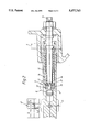
- FIG. 1 shows a partial longitudinal section through a gear-shift device constructed according to an embodiment of the invention, in which only those details which are required for an understanding of the invention are illustrated.
- FIG. 1a shows the detail A from FIG. 1 on an enlarged scale.
- FIG. 2 shows a section corresponding to that in FIG. 1 through the gear-shift device, which has been actuated into a position described as a first position.
- FIG. 2a shows the detail B in FIG. 2 on an enlarged scale.
- FIG. 3 shows a section corresponding to that in FIG. 1 through the gear-shift device, which has been actuated into a position described as a second position.
- FIG. 4 shows a section corresponding to that in FIG. 1 through the gear-shift device, which has been actuated into a position described as a fourth position.
- a selector shaft 10 is supported at each of its ends by a respective bearing arrangement 44 in a manner which allows it to be rotated and displaced axially in relation to a geometrical principal axis 16--16 of the gearbox casing.
- the other end of the selector shaft 10, which is not shown, passes through the shift-control housing 11 to the outside and is coupled kinematically in a known manner to a manual-shift lever in such a way that the selector shaft 10 is displaced axially by the selecting movements of the manual-shift lever and rotated by the gear-change movements of the manual-shift lever.
- the selector shaft 10 is provided in the customary manner with a selector finger 45, fixed in terms of movement relative to it, which, in the respective shift gate of the manual-shift lever, engages in articulated fashion in a coupling groove 46 of one of four selector rods 47, 48, 49, 50.
- the selector shaft 10 in FIG. 1 is in a rest position maintained by a centering spring 15. In this rest position the selector finger 45 engages in the coupling groove 46 of the selector rod 49 for the selection of the third and fourth forward gears, this position elsewhere being referred to and described as a third position 28 of the selector shaft 10.
- the selector shaft 10 has, in FIG. 2, been actuated into a first position 25, in which its selector finger 45 engages in the coupling groove 46 of the selector rod 47 used to select the first and the second forward gear.
- the selector shaft 10 has, in FIG. 3, been actuated into a second position 26, in which its selector finger 45 engages in the coupling groove 46 of the selector rod 48 used to select the reverse gear.
- the selector shaft 10 has, in FIG. 4, been actuated into a fourth position 51, in which its selector finger 45 engages in the coupling groove 46 of the selector rod 50 used to select a fifth and a sixth forward gear.
- the selector rods 47, 48, 49, 50 are supported in a manner which allows them to be displaced in a plane of the shift-control housing 11 parallel to the principal axis 16--16 and perpendicular to the plane of the drawing and are kinematically coupled in a known manner, by means of an associated selector fork, to the gear wheel clutch for coupling the freely revolving gear of the gear stage assigned to the associated speed.
- the end of the selector shaft 10 which is supported in the bearing arrangement 44 shown is designed as a sleeve-shaped stop part 12 into which there projects (forming a free annular space 18) a pin-shaped stop part 13 which is fixed coaxially with the principal axis 16--16 and in a manner fixed in terms of movement relative to the shift-control housing 11.
- a centering ring 30 Arranged in the annular space 18, in the following sequence--in relation to the first direction of the principal axis 16--16, that from the second position 26 of the selector shaft 10 to the first position 25 of the selector shaft 10--are a centering ring 30, a cylindrical return or centering spring 15, a reaction sleeve 14, a plurality of reaction balls 17 and a guide ring 39.
- the pin-shaped stop part 13 has a narrow pin section 22, which, in the second direction of the principal axis 16--16, merges via an inclined surface 24 into a first wide pin section 23 and, in the first direction of the principal axis 16--16, merges via an inclined surface 35 into a second wide pin section 36.
- the centering spring 15 is under prestress. Under the action of the prestress, the end 31 of the spring 15 remote from the reaction sleeve 14 is supported via the centering ring 30 both against a radial step 21 of the pin-shaped stop part 13, which step is used as an abutment fixed in relation to the housing, and against a retaining ring 33 used as an abutment that is fixed in relation to the selector shaft 10 and inserted into an inner circumferential groove in the sleeve-shaped stop part 12.
- the centering spring 15 is supported by its other end 32 against the adjacent end of the reaction sleeve 14, which is used as a spring stop 52.
- the other end of the reaction sleeve 14 is designed as a tapered inclined surface 20 which opens in the first direction of the principal axis 16--16 and by means of which the reaction sleeve 14 engages, under the action of the spring prestress, on the reaction balls 17. During this process, this reaction balls 17 are supported against the inclined surface 35 of the pin-shaped stop part 13. This inclined surface 35 is thus used as an axial abutment 34, fixed in relation to the housing 11, for the support of the spring force of the centering spring 15 in the first direction of the principal axis 16--16.
- the angle 37 of inclination of the inclined surface 20 on the reaction sleeve 14 is equal to or somewhat smaller than the angle 38 of inclination of the inclined surface 35 on the pin-shaped stop part 13 and, as a result, the reaction balls 17 are reliably pressed against the inclined surface 35 of the pin-shaped stop part 13 by the spring force and cannot travel radially outwards onto the circumference of the wide pin section 36.
- the guide ring 39 is free of forces in the unactuated condition of the gear-shift device, as can clearly be seen in detail from FIG. 1a.
- the guide ring 39 has respective radial guides 19 to support the reaction balls 17 axially in the first direction of the principal axis 16--16.
- the reaction sleeve 14 and the guide ring 39 furthermore each have a corresponding stop on their adjacent ends.
- the illustrative embodiment shown provides for the additional use of the inclined surface 20, which per se cooperates with the reaction balls 17, as the axial stop of the reaction sleeve 14 and for the formation of a corresponding inclined surface 27 on the guide ring 39 as an axial stop.
- stops 20, 27 are used to virtually bridge the reaction balls 17, i.e. keep them free of forces, during the actuation of the selector shaft 10 in the region 29 of the principal axis 16--16 defined by the first position 25 and the third position 28 illustrated.
- a radial step, used as axial stop 40, on the inner circumference of the sleeve-shaped stop part 12 comes to rest against the supporting surface of the guide ring 39, the surface remote from the reaction sleeve 14, which is used as corresponding stop 41.
- the supporting edge 55 of the radial guide 19 supporting the respective reaction ball 17 in the first direction of the principal axis 16--16 encloses an angle 56 of inclination with the inclined surface 20 of the reaction sleeve 14, the angle 58 between the supporting edge 55 and the principal axis 16--16 not necessarily being 90°.
- the reaction balls 17 have a radial play 43, relative to the narrow pin section 22.
- This radial play 43 is ensured by matching the clearance 59 between the vertex 57 of the angle 56 of inclination, on the one hand, and the principal axis 16--16 on the other--if the angle 37 of inclination of the inclined surface 20 is determined by the chosen magnitude of the gear-changing forces--to the diameters of the pin section 22 and of the reaction ball 17.
- This keeps the reaction ball 17 free of forces when the selector shaft 10 is actuated in that region 29 of the principal axis 16--16 which is defined by positions 25 and 28.
- the larger this clearance 59, the larger the play 43 because a larger clearance results, in turn, in an increase in the axial clearance between the supporting edge 55 and the inclined surface 20, allowing the reaction ball 17 to drift radially outwards somewhat.
Landscapes
- Engineering & Computer Science (AREA)
- General Engineering & Computer Science (AREA)
- Mechanical Engineering (AREA)
- Gear-Shifting Mechanisms (AREA)
- Arrangement Or Mounting Of Control Devices For Change-Speed Gearing (AREA)
Applications Claiming Priority (2)
| Application Number | Priority Date | Filing Date | Title |
|---|---|---|---|
| DE4313564A DE4313564C1 (de) | 1993-04-26 | 1993-04-26 | Schaltvorrichtung für ein Zahnräderwechselgetriebe eines Kraftfahrzeuges |
| DE4313564.1 | 1993-04-26 |
Publications (1)
| Publication Number | Publication Date |
|---|---|
| US5477742A true US5477742A (en) | 1995-12-26 |
Family
ID=6486355
Family Applications (1)
| Application Number | Title | Priority Date | Filing Date |
|---|---|---|---|
| US08/233,756 Expired - Lifetime US5477742A (en) | 1993-04-26 | 1994-04-26 | Gear-shift device for a change-speed gearbox of a motor vehicle |
Country Status (5)
| Country | Link |
|---|---|
| US (1) | US5477742A (fr) |
| KR (1) | KR0138723B1 (fr) |
| DE (1) | DE4313564C1 (fr) |
| FR (1) | FR2704616B1 (fr) |
| GB (1) | GB2277563B (fr) |
Cited By (10)
| Publication number | Priority date | Publication date | Assignee | Title |
|---|---|---|---|---|
| US5921136A (en) * | 1995-02-17 | 1999-07-13 | Dr. Ing. H.C.F. Porsche Ag | Shifting device for shifting transmission |
| GB2384533A (en) * | 2002-01-25 | 2003-07-30 | Eaton Corp | Gear shift cassette housing |
| US20040149071A1 (en) * | 2003-01-30 | 2004-08-05 | Crack David J. | Kickdown member for pedal assembly |
| US20040149072A1 (en) * | 2003-01-30 | 2004-08-05 | Kalsi Avtar S | Kickdown for pedal assembly |
| US20050262123A1 (en) * | 2002-08-13 | 2005-11-24 | Ses Japan Co., Ltd. | Data communication terminal unit |
| US20060005655A1 (en) * | 2001-04-02 | 2006-01-12 | Scheib Patrick L | First gear/reverse gate indicator switch |
| US20060230861A1 (en) * | 2005-04-05 | 2006-10-19 | Arvinmeritor Technology, Llc | Neutral switch system for transmission |
| US20060266147A1 (en) * | 2005-05-27 | 2006-11-30 | Bowen Thomas C | Shifter assembly for manual transmission |
| US10088042B2 (en) * | 2015-08-05 | 2018-10-02 | Fico Triad, S.A. | Shift selector mechanism for motor vehicle transmissions |
| US11439067B2 (en) * | 2019-09-10 | 2022-09-13 | Deere & Company | Shifting device for transmission having shifting device and harvesting machine |
Families Citing this family (2)
| Publication number | Priority date | Publication date | Assignee | Title |
|---|---|---|---|---|
| DE19805924A1 (de) * | 1998-02-13 | 1999-08-26 | Kochendoerfer & Kiep Stanz Und | Getriebe |
| DE10142189A1 (de) * | 2001-08-29 | 2003-03-20 | Ina Schaeffler Kg | Vorrichtung für die Erhöhung von Schaltkräften in einem Getriebe |
Citations (13)
| Publication number | Priority date | Publication date | Assignee | Title |
|---|---|---|---|---|
| US3164030A (en) * | 1963-04-16 | 1965-01-05 | Gen Motors Corp | Transmission control |
| US4070914A (en) * | 1976-09-17 | 1978-01-31 | Jack Reinhardt | Hydraulic clutch-controlled transmission gear detent system |
| US4275612A (en) * | 1978-03-30 | 1981-06-30 | Eaton Corporation | Shift control for change speed gear transmission for vehicle |
| US4377951A (en) * | 1980-01-09 | 1983-03-29 | Zahnradfabrik Friedrichshafen Ag | Gear-change mechanism for a gear-change transmission consisting of a main drive and a two-range group drive |
| DE3314411A1 (de) * | 1983-04-21 | 1984-10-25 | Dr.Ing.H.C. F. Porsche Ag, 7000 Stuttgart | Kraftfahrzeuggetriebe |
| US4531422A (en) * | 1983-08-29 | 1985-07-30 | Dana Corporation | Transmission shift rod interlock system |
| US4561321A (en) * | 1982-04-21 | 1985-12-31 | Dana Corporation | Shift bracket assembly |
| US4570776A (en) * | 1982-07-09 | 1986-02-18 | Sanshin Kogyo Kabushiki Kaisha | Detent mechanism for clutches |
| DE3704928A1 (de) * | 1987-02-17 | 1988-08-25 | Daimler Benz Ag | Vorrichtung zur erzeugung von rueckstellkraeften an einer mit einem handschalthebel gekoppelten schaltwelle eines gangwechselgetriebes |
| US5031472A (en) * | 1989-02-11 | 1991-07-16 | Eaton Corporation | Neutral sensing assembly |
| US5038632A (en) * | 1989-12-19 | 1991-08-13 | Dana Corporation | Transmission shift lever biasing assembly |
| US5109722A (en) * | 1990-01-12 | 1992-05-05 | The Toro Company | Self-detenting transmission shift key |
| US5140866A (en) * | 1989-06-29 | 1992-08-25 | Zahnradfabrik Friedrichshafen Ag | Gearshift device for a multiple-gear gear change box in a motor |
-
1993
- 1993-04-26 DE DE4313564A patent/DE4313564C1/de not_active Expired - Fee Related
-
1994
- 1994-04-13 GB GB9407286A patent/GB2277563B/en not_active Expired - Fee Related
- 1994-04-22 FR FR9404882A patent/FR2704616B1/fr not_active Expired - Fee Related
- 1994-04-25 KR KR1019940008673A patent/KR0138723B1/ko not_active IP Right Cessation
- 1994-04-26 US US08/233,756 patent/US5477742A/en not_active Expired - Lifetime
Patent Citations (13)
| Publication number | Priority date | Publication date | Assignee | Title |
|---|---|---|---|---|
| US3164030A (en) * | 1963-04-16 | 1965-01-05 | Gen Motors Corp | Transmission control |
| US4070914A (en) * | 1976-09-17 | 1978-01-31 | Jack Reinhardt | Hydraulic clutch-controlled transmission gear detent system |
| US4275612A (en) * | 1978-03-30 | 1981-06-30 | Eaton Corporation | Shift control for change speed gear transmission for vehicle |
| US4377951A (en) * | 1980-01-09 | 1983-03-29 | Zahnradfabrik Friedrichshafen Ag | Gear-change mechanism for a gear-change transmission consisting of a main drive and a two-range group drive |
| US4561321A (en) * | 1982-04-21 | 1985-12-31 | Dana Corporation | Shift bracket assembly |
| US4570776A (en) * | 1982-07-09 | 1986-02-18 | Sanshin Kogyo Kabushiki Kaisha | Detent mechanism for clutches |
| DE3314411A1 (de) * | 1983-04-21 | 1984-10-25 | Dr.Ing.H.C. F. Porsche Ag, 7000 Stuttgart | Kraftfahrzeuggetriebe |
| US4531422A (en) * | 1983-08-29 | 1985-07-30 | Dana Corporation | Transmission shift rod interlock system |
| DE3704928A1 (de) * | 1987-02-17 | 1988-08-25 | Daimler Benz Ag | Vorrichtung zur erzeugung von rueckstellkraeften an einer mit einem handschalthebel gekoppelten schaltwelle eines gangwechselgetriebes |
| US5031472A (en) * | 1989-02-11 | 1991-07-16 | Eaton Corporation | Neutral sensing assembly |
| US5140866A (en) * | 1989-06-29 | 1992-08-25 | Zahnradfabrik Friedrichshafen Ag | Gearshift device for a multiple-gear gear change box in a motor |
| US5038632A (en) * | 1989-12-19 | 1991-08-13 | Dana Corporation | Transmission shift lever biasing assembly |
| US5109722A (en) * | 1990-01-12 | 1992-05-05 | The Toro Company | Self-detenting transmission shift key |
Cited By (13)
| Publication number | Priority date | Publication date | Assignee | Title |
|---|---|---|---|---|
| US5921136A (en) * | 1995-02-17 | 1999-07-13 | Dr. Ing. H.C.F. Porsche Ag | Shifting device for shifting transmission |
| US20060005655A1 (en) * | 2001-04-02 | 2006-01-12 | Scheib Patrick L | First gear/reverse gate indicator switch |
| GB2384533A (en) * | 2002-01-25 | 2003-07-30 | Eaton Corp | Gear shift cassette housing |
| US20050262123A1 (en) * | 2002-08-13 | 2005-11-24 | Ses Japan Co., Ltd. | Data communication terminal unit |
| US20040149072A1 (en) * | 2003-01-30 | 2004-08-05 | Kalsi Avtar S | Kickdown for pedal assembly |
| US6955103B2 (en) * | 2003-01-30 | 2005-10-18 | Teleflex Incorporated | Kickdown member for pedal assembly |
| US20040149071A1 (en) * | 2003-01-30 | 2004-08-05 | Crack David J. | Kickdown member for pedal assembly |
| US7017443B2 (en) * | 2003-01-30 | 2006-03-28 | Drivesol Worldwide, Inc. | Kickdown for pedal assembly |
| US20060230861A1 (en) * | 2005-04-05 | 2006-10-19 | Arvinmeritor Technology, Llc | Neutral switch system for transmission |
| US7540209B2 (en) * | 2005-04-05 | 2009-06-02 | Arvinmeritor Technology, Llc | Neutral switch system for transmission |
| US20060266147A1 (en) * | 2005-05-27 | 2006-11-30 | Bowen Thomas C | Shifter assembly for manual transmission |
| US10088042B2 (en) * | 2015-08-05 | 2018-10-02 | Fico Triad, S.A. | Shift selector mechanism for motor vehicle transmissions |
| US11439067B2 (en) * | 2019-09-10 | 2022-09-13 | Deere & Company | Shifting device for transmission having shifting device and harvesting machine |
Also Published As
| Publication number | Publication date |
|---|---|
| FR2704616B1 (fr) | 1998-08-14 |
| DE4313564C1 (de) | 1994-06-23 |
| GB2277563B (en) | 1996-04-03 |
| FR2704616A1 (fr) | 1994-11-04 |
| KR0138723B1 (ko) | 1998-04-30 |
| GB9407286D0 (en) | 1994-06-08 |
| GB2277563A (en) | 1994-11-02 |
Similar Documents
| Publication | Publication Date | Title |
|---|---|---|
| US5477742A (en) | Gear-shift device for a change-speed gearbox of a motor vehicle | |
| US4060005A (en) | Transmission assembly comprising a main gearbox in series with countershafting providing at least two gear ratios | |
| GB2068065A (en) | Cable operating gimbal automotive transmission shifter and gear lockout | |
| US4315698A (en) | Coupling sleeve | |
| US5823053A (en) | Gear-shift device for a change-speed gearbox | |
| US8056433B2 (en) | Shifting device for a manual transmission of a vehicle | |
| US4532823A (en) | Concentric shift rail mechanism | |
| EP0898099A2 (fr) | Dispositif automatisé de changement de vitesse pour une boíte de transmission | |
| US6729200B2 (en) | Selector device for a change-speed gearbox | |
| US5778728A (en) | Gear shifting device for a change-speed gearbox, particularly for motor vehicles | |
| KR0123944B1 (ko) | 자동차 톱니변환 전달용 축장치 | |
| US4344334A (en) | Change-speed transmission with speed-range selection means for motor vehicles, particularly for farm tractors | |
| US20060266147A1 (en) | Shifter assembly for manual transmission | |
| KR20010023379A (ko) | 변속 기어박스를 위한 기어변속장치 | |
| US4133219A (en) | Transmission shift control mechanism | |
| US5718150A (en) | Gearshift device for the change-speed gearbox of a motor vehicle | |
| US4319496A (en) | Fork rod slidably supporting device for transfer of vehicles | |
| US5063794A (en) | Shift key having shoulder | |
| CA1167285A (fr) | Calage de changement de plages, sur trains d'engrenages, tributaire de la vitesse de roulage | |
| JPH0125805Y2 (fr) | ||
| US3043413A (en) | Transmission control | |
| GB2127503A (en) | Selector mechanism having a manual gearshift lever for main and auxiliary gearboxes in series | |
| US3818779A (en) | Manual transmission shift control | |
| JPH02150569A (ja) | 手動変速機のセレクト荷重機構 | |
| JPS6360262B2 (fr) |
Legal Events
| Date | Code | Title | Description |
|---|---|---|---|
| AS | Assignment |
Owner name: MERCEDES-BENZ AG Free format text: ASSIGNMENT OF ASSIGNORS INTEREST;ASSIGNOR:BURGER, HANS;REEL/FRAME:006976/0780 Effective date: 19940414 |
|
| STCF | Information on status: patent grant |
Free format text: PATENTED CASE |
|
| AS | Assignment |
Owner name: DAIMLER-BENZ AKTIENGESELLSCHAFT, GERMANY Free format text: MERGER;ASSIGNOR:MERCEDES-BENZ AG;REEL/FRAME:009360/0937 Effective date: 19970605 Owner name: DAIMLER-BENZ AKTIENGESELLSCHAFT, GERMANY Free format text: MERGER RE-RECORD TO CORRECT THE NUMBER OF MICROFILM PAGES FROM 60 TO 98 AT REEL 9360, FRAME 0937.;ASSIGNOR:MERCEDES-BENZ AG;REEL/FRAME:009827/0145 Effective date: 19970605 |
|
| FPAY | Fee payment |
Year of fee payment: 4 |
|
| AS | Assignment |
Owner name: DAIMLERCHRYSLER AG, GERMANY Free format text: MERGER;ASSIGNOR:DAIMLER-BENZ AKTIENGESELLSCHAFT;REEL/FRAME:010133/0556 Effective date: 19990108 |
|
| FEPP | Fee payment procedure |
Free format text: PAYOR NUMBER ASSIGNED (ORIGINAL EVENT CODE: ASPN); ENTITY STATUS OF PATENT OWNER: LARGE ENTITY |
|
| FPAY | Fee payment |
Year of fee payment: 8 |
|
| FPAY | Fee payment |
Year of fee payment: 12 |
|
| AS | Assignment |
Owner name: DAIMLER AG, GERMANY Free format text: CHANGE OF NAME;ASSIGNOR:DAIMLERCHRYSLER AG;REEL/FRAME:020976/0889 Effective date: 20071019 Owner name: DAIMLER AG,GERMANY Free format text: CHANGE OF NAME;ASSIGNOR:DAIMLERCHRYSLER AG;REEL/FRAME:020976/0889 Effective date: 20071019 |
|
| AS | Assignment |
Owner name: DAIMLER AG, GERMANY Free format text: CORRECTIVE ASSIGNMENT TO CORRECT THE APPLICATION NO. 10/567,810 PREVIOUSLY RECORDED ON REEL 020976 FRAME 0889. ASSIGNOR(S) HEREBY CONFIRMS THE CHANGE OF NAME;ASSIGNOR:DAIMLERCHRYSLER AG;REEL/FRAME:053583/0493 Effective date: 20071019 |