US5463961A - Motorized track guided vehicle for infants with soothing track bumps - Google Patents
Motorized track guided vehicle for infants with soothing track bumps Download PDFInfo
- Publication number
- US5463961A US5463961A US08/161,413 US16141393A US5463961A US 5463961 A US5463961 A US 5463961A US 16141393 A US16141393 A US 16141393A US 5463961 A US5463961 A US 5463961A
- Authority
- US
- United States
- Prior art keywords
- assembly
- truck assembly
- track
- truck
- rails
- Prior art date
- Legal status (The legal status is an assumption and is not a legal conclusion. Google has not performed a legal analysis and makes no representation as to the accuracy of the status listed.)
- Expired - Fee Related
Links
Images


Classifications
-
- A—HUMAN NECESSITIES
- A63—SPORTS; GAMES; AMUSEMENTS
- A63G—MERRY-GO-ROUNDS; SWINGS; ROCKING-HORSES; CHUTES; SWITCHBACKS; SIMILAR DEVICES FOR PUBLIC AMUSEMENT
- A63G25/00—Autocar-like self-drivers; Runways therefor
-
- B—PERFORMING OPERATIONS; TRANSPORTING
- B61—RAILWAYS
- B61C—LOCOMOTIVES; MOTOR RAILCARS
- B61C13/00—Locomotives or motor railcars characterised by their application to special systems or purposes
- B61C13/04—Locomotives or motor railcars characterised by their application to special systems or purposes for elevated railways with rigid rails
Definitions
- the present invention relates to a motorized vehicle for infants and associated track assembly.
- Motorized recreational vehicles which are disposed on a track are well known. These vehicles are generally large enough to carry several occupants and typically are capable of relatively high speed (e.g. roller coaster). While these arrangements are generally satisfactory for transporting adults and young children they are not adaptable for use with infants.
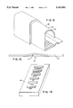
- FIG. 1 shows a perspective view of the present invention mounted on a section of track.
- FIG. 2 shows a top view of the present invention.
- FIG. 3a shows the underside of the present invention.
- FIG. 3b shows the stopper arrangement
- FIG. 4 shows a side view of the present invention with a cutaway portion showing the battery and motor.
- FIG. 5 shows a frontal view of the present invention and the details of the spring loaded safety contact arrangement.
- FIG. 6 shows a side view of a wheel which can be used with the present invention.
- FIG. 7 shows a perspective view of the platform associated with the present invention mounted along a section of track with a cutaway portion showing the way the wheels are disposed inside the rails.
- FIG. 8 shows a perspective view of the track assembly.
- FIGS. 9a-b show shows the connectors for connecting the track rails.
- FIG. 10 shows a cross section of the rail.
- FIG. 11 shows a perspective view of a large end of a rail.
- FIG. 12 shows a perspective view of a connection point of two rails.
- FIG. 13 shows a side view of a ramp section.
- FIG. 14 shows a top view of the remote control.
- the invention comprises a truck assembly 20 which rides along the track 22 and is capable of supporting various types of known infant supporting devices.
- the truck assembly 20 has a top surface 24. Connected to the top surface 24 are a plurality of fastening belts 26 for securing an infant support device such as a baby carrier, car seat, bassinet or the like.
- the belts 26 include connectors 28 and are adjustable to accommodate infant support devices having different dimensions.
- FIG. 3a shows the underside of the truck assembly 20 which is supported by front 30 and rear 32 suspension assemblies which are connected to the underside 34 of the truck assembly 20.
- the truck assembly 20 includes a motor 36 which is mounted over the rear suspension assembly 32 so as to supply power to the rear wheels 38 for propelling the truck assembly 20.
- FIG. 3b shows a closeup of the stopper 33 of the truck assembly 20.
- the stopper 33 and the end of track stop 35 cooperate to prevent the truck assembly 20 from rolling off the end of the track 22.
- Both the track stop 35 and the stopper 33 can either be spring loaded or made of a hard rubber to provide a cushioning effect when the truck assembly 20 reaches the end of the track 22.
- the motor 36 is capable of reversal so that the truck assembly 20 can be operated in the forward or reverse direction. Reversal can be effected by way of a toggle switch (not shown) or by way of a reverse gear mechanism as is well known in the art.
- motor 36 is an electric motor powered by a battery 40.
- FIG. 4 is a side view of the truck assembly mounted on a section of the track 22. A cutaway portion shows the position of the battery 40 and the motor 36. Also shown is a self reeling cord 42 and the associated reel assembly 44. The cord 42 is connected to a remote control 46 which will be described later. The reel assembly 44 is mounted behind the rear wheel assembly 32 so that the cord 42 does not get tangled with the wheel assemblies 30, 32.
- the reel assembly 44 operates in combination with the motor 36 to keep the cord 42 from developing slack.
- the reel assembly 44 is spring loaded so that the amount of cord 42 reeled or unreeled is proportional to the travel of the truck assembly 20.
- FIG. 5 shows a contact assembly 50 which acts as a safety feature.
- the contact assembly 50 is operatively connected to the front bumper assembly 51 so that it is disengaged when the front bumper 51 contacts any object in the track 22.
- the contacts 54 and 56 are electrically connected to a conductor arrangement (not shown) which supplies power from the battery 40 to the motor 36.
- the truck assembly 20 will not move unless the obstruction is removed causing contacts 54 and 56 to touch thereby allowing electrical current to flow from the battery 40 to the motor 36.
- FIG. 6 shows a side view of one embodiment of a wheel 48 which can be used with the present invention.
- the wheel 48 has a plurality of transversally extending raised rectangular sections 66. These raised sections 66 serve to transmit vibration to the truck assembly 20 and ultimately to the infant support device. The vibration provides a soothing effect on the infant.
- FIG. 7 shows a closeup of the truck assembly 20 with the wheels 48 mounted inside the rails 70. As can be seen the wheels 48 fit completely inside the rails 70.
- the track 22 comprises two rails 70 which are connected by a series of evenly spaced ties 72 which serve to stabilize the rails 70 as well as keep them evenly spaced.
- the rails 70 can be provided with a series of rectangular raised sections 74 which serve to impart vibration in the same manner as raised sections 66. Also the rails 70 have large ends and small ends to facilitate connecting of rails 70 as will be explained later.
- Ties 72 can be provided with a horizontally extending lip 76 or with a vertical support member 75 as shown in FIGS. 9(a) and (b).
- FIG. 10 shows a cross sectional view of a rail 70.
- the rail 70 has a vertically extending wall 80 which has a downwardly extending arc shaped portion 82 which is adapted to receive the wheel 48.
- Rail 70 also has an integrally formed horizontally extending section 84 which provides a surface for wheel 48.
- the horizontal section 84 has a centrally located raised portion 86 which serves as a retainer wall for the wheels 48.
- wheels 48 are secured onto the rails 70 by way of wall 80, arc shaped portion 82, and raised portion 86.
- arc shaped portion 82 acts to prevent the truck assembly 20 from tipping over since the wheels have only limited range of vertical motion.
- the rails 70 can be made of any suitable rigid material such as steel or other metal.
- the rails 70 come in a plurality of sections 90 so that the length and the course of the track 22 can be adjusted. Curved sections 90 can be provided so that an oval track course can be laid out.
- FIG. 11 a perspective view of one rail 70 of a track section 90 is shown. Specfically the large end 92 of a rail 70 is shown. The large end 92 is adapted to receive the small end 94 (FIG. 12) of the connecting rail 70. The small end 94 is slidably received into the large end 92 of the rail between points 96 and 98 until it is flush with stop point 100. The outer surface 102 of of the small end 94 is frictionally engaged with the inner surface 104 of the large end 92 so as to provide a secure connection between connecting rails 70 as is shown in FIG. 12.
- FIG. 13 shows a track section 90 having an inclined portion or ramp 110.
- This track section 90 is connected in the manner discussed above and can be added to provide a rolling terrain effect to the occupant.
- FIG. 14 shows the remote control 46.
- the stop and go switches act as off and on switches for the motor 36. Either the forward or reverse switch is always engaged.
- the motor 36 is capable of operating at three speeds; an intermediate speed when the go switch is depressed, a fast speed when the high switch is depressed, and a slow speed when the low switch is depressed.
Landscapes
- Engineering & Computer Science (AREA)
- Transportation (AREA)
- Mechanical Engineering (AREA)
- Toys (AREA)
Abstract
A motorized amusement device especially designed for infants is provided. The device includes a truck assembly for securing a pre-existing infant support device such as a car seat. A reconfigurable track assembly is provided so that the device can be used without rearranging existing decor. The device can be operated by remote control and includes aumtomatic safety features.
Description
The present invention relates to a motorized vehicle for infants and associated track assembly.
Motorized recreational vehicles which are disposed on a track are well known. These vehicles are generally large enough to carry several occupants and typically are capable of relatively high speed (e.g. roller coaster). While these arrangements are generally satisfactory for transporting adults and young children they are not adaptable for use with infants.
It is an object of this invention to provide a motorized vehicle which can be used as an amusement device for infants.
It is another object of this invention to provide a motorized vehicle for infants which moves along a reconfigurable track.
It is another object of this invention to provide a motorized vehicle for infants which can be operated by remote control.
It is another object of this invention to provide a motorized vehicle for infants which is reversible.
It is yet another object of this invention to provide a motorized vehicle for infants which is capable of transmitting vibration to the occupants.
It is still another object of the invention to provide a motorized vehicle for infants which has an anti-rollover feature.
It is another object of the invention to provide a motorized vehicle for infants which has interchangeable seats.
FIG. 1 shows a perspective view of the present invention mounted on a section of track.
FIG. 2 shows a top view of the present invention.
FIG. 3a shows the underside of the present invention.
FIG. 3b shows the stopper arrangement.
FIG. 4 shows a side view of the present invention with a cutaway portion showing the battery and motor.
FIG. 5 shows a frontal view of the present invention and the details of the spring loaded safety contact arrangement.
FIG. 6 shows a side view of a wheel which can be used with the present invention.
FIG. 7 shows a perspective view of the platform associated with the present invention mounted along a section of track with a cutaway portion showing the way the wheels are disposed inside the rails.
FIG. 8 shows a perspective view of the track assembly.
FIGS. 9a-b show shows the connectors for connecting the track rails.
FIG. 10 shows a cross section of the rail.
FIG. 11 shows a perspective view of a large end of a rail.
FIG. 12 shows a perspective view of a connection point of two rails.
FIG. 13 shows a side view of a ramp section.
FIG. 14 shows a top view of the remote control.
Referring now to FIG. 1, a perspective view of the present invention, 10 is shown. The invention comprises a truck assembly 20 which rides along the track 22 and is capable of supporting various types of known infant supporting devices.
Referring to FIG. 2, a top view of the truck assembly 20 is shown. The truck assembly has a top surface 24. Connected to the top surface 24 are a plurality of fastening belts 26 for securing an infant support device such as a baby carrier, car seat, bassinet or the like. The belts 26 include connectors 28 and are adjustable to accommodate infant support devices having different dimensions.
FIG. 3a shows the underside of the truck assembly 20 which is supported by front 30 and rear 32 suspension assemblies which are connected to the underside 34 of the truck assembly 20. The truck assembly 20 includes a motor 36 which is mounted over the rear suspension assembly 32 so as to supply power to the rear wheels 38 for propelling the truck assembly 20.
FIG. 3b shows a closeup of the stopper 33 of the truck assembly 20. The stopper 33 and the end of track stop 35 cooperate to prevent the truck assembly 20 from rolling off the end of the track 22. Both the track stop 35 and the stopper 33 can either be spring loaded or made of a hard rubber to provide a cushioning effect when the truck assembly 20 reaches the end of the track 22.
The motor 36 is capable of reversal so that the truck assembly 20 can be operated in the forward or reverse direction. Reversal can be effected by way of a toggle switch (not shown) or by way of a reverse gear mechanism as is well known in the art.
In the preferred embodiment motor 36 is an electric motor powered by a battery 40.
FIG. 4 is a side view of the truck assembly mounted on a section of the track 22. A cutaway portion shows the position of the battery 40 and the motor 36. Also shown is a self reeling cord 42 and the associated reel assembly 44. The cord 42 is connected to a remote control 46 which will be described later. The reel assembly 44 is mounted behind the rear wheel assembly 32 so that the cord 42 does not get tangled with the wheel assemblies 30, 32.
The reel assembly 44 operates in combination with the motor 36 to keep the cord 42 from developing slack. The reel assembly 44 is spring loaded so that the amount of cord 42 reeled or unreeled is proportional to the travel of the truck assembly 20.
FIG. 5 shows a contact assembly 50 which acts as a safety feature. The contact assembly 50 is operatively connected to the front bumper assembly 51 so that it is disengaged when the front bumper 51 contacts any object in the track 22. The contacts 54 and 56 are electrically connected to a conductor arrangement (not shown) which supplies power from the battery 40 to the motor 36. The truck assembly 20 will not move unless the obstruction is removed causing contacts 54 and 56 to touch thereby allowing electrical current to flow from the battery 40 to the motor 36.
FIG. 6 shows a side view of one embodiment of a wheel 48 which can be used with the present invention. The wheel 48 has a plurality of transversally extending raised rectangular sections 66. These raised sections 66 serve to transmit vibration to the truck assembly 20 and ultimately to the infant support device. The vibration provides a soothing effect on the infant.
FIG. 7 shows a closeup of the truck assembly 20 with the wheels 48 mounted inside the rails 70. As can be seen the wheels 48 fit completely inside the rails 70.
Referring now to FIG. 8 the track 22 comprises two rails 70 which are connected by a series of evenly spaced ties 72 which serve to stabilize the rails 70 as well as keep them evenly spaced. The rails 70 can be provided with a series of rectangular raised sections 74 which serve to impart vibration in the same manner as raised sections 66. Also the rails 70 have large ends and small ends to facilitate connecting of rails 70 as will be explained later.
FIG. 10 shows a cross sectional view of a rail 70. The rail 70 has a vertically extending wall 80 which has a downwardly extending arc shaped portion 82 which is adapted to receive the wheel 48. Rail 70 also has an integrally formed horizontally extending section 84 which provides a surface for wheel 48. The horizontal section 84 has a centrally located raised portion 86 which serves as a retainer wall for the wheels 48. Thus wheels 48 are secured onto the rails 70 by way of wall 80, arc shaped portion 82, and raised portion 86. It can be appreciated that arc shaped portion 82 acts to prevent the truck assembly 20 from tipping over since the wheels have only limited range of vertical motion. The rails 70 can be made of any suitable rigid material such as steel or other metal.
The rails 70 come in a plurality of sections 90 so that the length and the course of the track 22 can be adjusted. Curved sections 90 can be provided so that an oval track course can be laid out. Referring now to FIG. 11, a perspective view of one rail 70 of a track section 90 is shown. Specfically the large end 92 of a rail 70 is shown. The large end 92 is adapted to receive the small end 94 (FIG. 12) of the connecting rail 70. The small end 94 is slidably received into the large end 92 of the rail between points 96 and 98 until it is flush with stop point 100. The outer surface 102 of of the small end 94 is frictionally engaged with the inner surface 104 of the large end 92 so as to provide a secure connection between connecting rails 70 as is shown in FIG. 12.
FIG. 13 shows a track section 90 having an inclined portion or ramp 110. This track section 90 is connected in the manner discussed above and can be added to provide a rolling terrain effect to the occupant.
FIG. 14 shows the remote control 46. The stop and go switches act as off and on switches for the motor 36. Either the forward or reverse switch is always engaged. The motor 36 is capable of operating at three speeds; an intermediate speed when the go switch is depressed, a fast speed when the high switch is depressed, and a slow speed when the low switch is depressed.
Claims (5)
1. A motorized vehicle assembly for infants comprising:
a Truck assembly having front and rear wheel assemblies extending downwardly therefrom, the front and rear wheel assemblies each having wheels connected thereto, said wheels having radially extending rectangular projections thereon for imparting vibration to said truck assembly;
a track assembly having two parallel rails, each of said rails being adapted to guide and limit the movement of said wheels, said rails having a series of regularly spaced rectangular projections for imparting additional vibration to said truck assembly;
a motor contained within the truck assembly and adapted to impart rotation to the wheels connected to the rear wheel assembly thereby causing the truck assembly to move along said rails, said motor connected to a remote control by a spring loaded cord assembly, said cord assembly serving to provide control signals to said motor from said remote control;
the truck assembly having a longitudinally extending top surface having fastening means connected thereto, the fastening means secured to at least three points along the length of the top surface, the fastening means securing an infant support device to said surface.
2. The vehicle of claim 1 where said truck assembly can operate in two directions along said track assembly.
3. The vehicle of claim 1 where said track assembly is reconfigurable.
4. The vehicle of claim 1 where said motor is operable by remote control.
5. The vehicle of claim 1 where said truck assembly includes a safety contact arrangement effective to disable the truck assembly upon contact with any object which impedes motion along the truck assembly.
Priority Applications (1)
| Application Number | Priority Date | Filing Date | Title |
|---|---|---|---|
| US08/161,413 US5463961A (en) | 1993-12-06 | 1993-12-06 | Motorized track guided vehicle for infants with soothing track bumps |
Applications Claiming Priority (1)
| Application Number | Priority Date | Filing Date | Title |
|---|---|---|---|
| US08/161,413 US5463961A (en) | 1993-12-06 | 1993-12-06 | Motorized track guided vehicle for infants with soothing track bumps |
Publications (1)
| Publication Number | Publication Date |
|---|---|
| US5463961A true US5463961A (en) | 1995-11-07 |
Family
ID=22581084
Family Applications (1)
| Application Number | Title | Priority Date | Filing Date |
|---|---|---|---|
| US08/161,413 Expired - Fee Related US5463961A (en) | 1993-12-06 | 1993-12-06 | Motorized track guided vehicle for infants with soothing track bumps |
Country Status (1)
| Country | Link |
|---|---|
| US (1) | US5463961A (en) |
Cited By (14)
| Publication number | Priority date | Publication date | Assignee | Title |
|---|---|---|---|---|
| EP0923480A1 (en) * | 1996-09-05 | 1999-06-23 | J. Kirston Henderson | Machine for transport of passengers and cargo |
| US5935012A (en) * | 1998-09-10 | 1999-08-10 | Cohn; Irv | Wheeled child seat with track |
| US20030203759A1 (en) * | 2002-04-30 | 2003-10-30 | Ride Tek Engineering S.R.L. | Mechanized structures for the launch of cars in installations for amusement parks such as, for instance, roller coasters or similar attractions |
| US20070078466A1 (en) * | 2005-09-30 | 2007-04-05 | Restoration Robotics, Inc. | Methods for harvesting follicular units using an automated system |
| US20070120404A1 (en) * | 2005-11-03 | 2007-05-31 | Graco Children's Products Inc. | Child Motion Device |
| US20070205646A1 (en) * | 2006-03-02 | 2007-09-06 | Mattel, Inc. | Repositionable Child Support Device |
| US20140144346A1 (en) * | 2012-05-09 | 2014-05-29 | Albert Daniel Houston | Infant soothing carrier assembly and apparatus |
| US8827366B2 (en) | 2008-09-03 | 2014-09-09 | Thorley Industries Llc | Infant care apparatus |
| US20140251733A1 (en) * | 2011-11-08 | 2014-09-11 | Dwight Fry | Apparatus For Ascending And Descending Stairs With A Wheelchair |
| US9033415B2 (en) | 2013-03-15 | 2015-05-19 | Thorley Industries Llc | Driven infant seat |
| US9220991B2 (en) | 2013-11-18 | 2015-12-29 | Mattel, Inc. | Children's ride-on vehicles and play systems incorporating wheel and track assemblies |
| US9221470B2 (en) | 2013-11-18 | 2015-12-29 | Mattel, Inc. | Children's ride-on vehicles and play systems incorporating wheel and track assemblies |
| CN105686938A (en) * | 2016-01-15 | 2016-06-22 | 张锐 | Intestinal tract flatulence vibration massage device |
| US9623342B2 (en) | 2013-11-18 | 2017-04-18 | Mattel, Inc. | Track assemblies and track assembly kits for children's ride-on vehicles |
Citations (5)
| Publication number | Priority date | Publication date | Assignee | Title |
|---|---|---|---|---|
| US1165898A (en) * | 1913-10-30 | 1915-12-28 | Charles F Peck | Horse-ride amusement device. |
| US1370385A (en) * | 1920-11-08 | 1921-03-01 | Unger Morris | Amusement device |
| US2888086A (en) * | 1957-09-06 | 1959-05-26 | Daniel C O'brien | Carriage oscillating device |
| US3675586A (en) * | 1969-09-19 | 1972-07-11 | Albert G Haddad | Control system for dual rail model electric vehicles |
| US4991516A (en) * | 1988-10-11 | 1991-02-12 | Wolfgang Rixen | Transport system for workpieces |
-
1993
- 1993-12-06 US US08/161,413 patent/US5463961A/en not_active Expired - Fee Related
Patent Citations (5)
| Publication number | Priority date | Publication date | Assignee | Title |
|---|---|---|---|---|
| US1165898A (en) * | 1913-10-30 | 1915-12-28 | Charles F Peck | Horse-ride amusement device. |
| US1370385A (en) * | 1920-11-08 | 1921-03-01 | Unger Morris | Amusement device |
| US2888086A (en) * | 1957-09-06 | 1959-05-26 | Daniel C O'brien | Carriage oscillating device |
| US3675586A (en) * | 1969-09-19 | 1972-07-11 | Albert G Haddad | Control system for dual rail model electric vehicles |
| US4991516A (en) * | 1988-10-11 | 1991-02-12 | Wolfgang Rixen | Transport system for workpieces |
Cited By (24)
| Publication number | Priority date | Publication date | Assignee | Title |
|---|---|---|---|---|
| EP0923480A1 (en) * | 1996-09-05 | 1999-06-23 | J. Kirston Henderson | Machine for transport of passengers and cargo |
| EP0923480A4 (en) * | 1996-09-05 | 2000-06-28 | J Kirston Henderson | Machine for transport of passengers and cargo |
| US5935012A (en) * | 1998-09-10 | 1999-08-10 | Cohn; Irv | Wheeled child seat with track |
| US20030203759A1 (en) * | 2002-04-30 | 2003-10-30 | Ride Tek Engineering S.R.L. | Mechanized structures for the launch of cars in installations for amusement parks such as, for instance, roller coasters or similar attractions |
| US20070078466A1 (en) * | 2005-09-30 | 2007-04-05 | Restoration Robotics, Inc. | Methods for harvesting follicular units using an automated system |
| US20070120404A1 (en) * | 2005-11-03 | 2007-05-31 | Graco Children's Products Inc. | Child Motion Device |
| US7717798B2 (en) * | 2005-11-03 | 2010-05-18 | Graco Children's Products Inc. | Child motion device |
| US20070205646A1 (en) * | 2006-03-02 | 2007-09-06 | Mattel, Inc. | Repositionable Child Support Device |
| US7722118B2 (en) | 2006-03-02 | 2010-05-25 | Mattel, Inc. | Repositionable child support device |
| US9642474B2 (en) | 2008-09-03 | 2017-05-09 | Thorley Industries Llc | Infant care apparatus |
| US8827366B2 (en) | 2008-09-03 | 2014-09-09 | Thorley Industries Llc | Infant care apparatus |
| US11684173B2 (en) | 2008-09-03 | 2023-06-27 | Thorley Industries, Llc | Infant care apparatus |
| US10231555B2 (en) | 2008-09-03 | 2019-03-19 | Thorley Industries Llc | Infant care apparatus |
| US9763524B2 (en) | 2008-09-03 | 2017-09-19 | Thorley Industries Llc | Infant care apparatus |
| US9708162B2 (en) * | 2011-11-08 | 2017-07-18 | Dwight Fry | Apparatus for ascending and descending stairs with a wheelchair |
| US20140251733A1 (en) * | 2011-11-08 | 2014-09-11 | Dwight Fry | Apparatus For Ascending And Descending Stairs With A Wheelchair |
| US9597478B2 (en) * | 2012-05-09 | 2017-03-21 | Albert Daniel Houston | Infant soothing carrier assembly and apparatus |
| US20140144346A1 (en) * | 2012-05-09 | 2014-05-29 | Albert Daniel Houston | Infant soothing carrier assembly and apparatus |
| US9033415B2 (en) | 2013-03-15 | 2015-05-19 | Thorley Industries Llc | Driven infant seat |
| US9220991B2 (en) | 2013-11-18 | 2015-12-29 | Mattel, Inc. | Children's ride-on vehicles and play systems incorporating wheel and track assemblies |
| US9623342B2 (en) | 2013-11-18 | 2017-04-18 | Mattel, Inc. | Track assemblies and track assembly kits for children's ride-on vehicles |
| US9221470B2 (en) | 2013-11-18 | 2015-12-29 | Mattel, Inc. | Children's ride-on vehicles and play systems incorporating wheel and track assemblies |
| CN105686938B (en) * | 2016-01-15 | 2017-07-04 | 张锐 | A kind of intestinal tract flatulence vibration masseur |
| CN105686938A (en) * | 2016-01-15 | 2016-06-22 | 张锐 | Intestinal tract flatulence vibration massage device |
Similar Documents
| Publication | Publication Date | Title |
|---|---|---|
| US5463961A (en) | Motorized track guided vehicle for infants with soothing track bumps | |
| US4516953A (en) | Toy vehicular playset | |
| US6220171B1 (en) | Amusement ride | |
| JPH067547A (en) | Slot racing truck device | |
| US10596476B2 (en) | Toy vehicle track set | |
| US5074220A (en) | Overhead monorail transit system employing carriage with upper guide wheel and guideway with concave upper surface | |
| ATE262967T1 (en) | FACILITY FOR AMUSEMENT PARK CALLED ROLLER COASTER | |
| US5479998A (en) | Electronic powered motor vehicle | |
| US3532060A (en) | Transportation system and vehicle | |
| US5935012A (en) | Wheeled child seat with track | |
| US4417523A (en) | Rideable motor-driven toy train | |
| US11459706B1 (en) | Rapid transit system with wheel in track design | |
| KR101872581B1 (en) | Detachable electric driving device | |
| JPH05131920A (en) | Hybrid-type circulation cableway usable with railway | |
| JP2609930B2 (en) | Orbiting recreational vehicles | |
| JP4831881B2 (en) | Cart carrier | |
| EP0987141A3 (en) | Restraint system for a child seat carried in a motor vehicle | |
| JP2006044355A (en) | Collision overturning prevention device for vehicle | |
| US20230294743A1 (en) | Rapid transit system with wheel in track design | |
| US20210379500A1 (en) | Tubular Transport System With Motorized Vehicle | |
| JPH0357762A (en) | Load transporting device | |
| JPS6024678Y2 (en) | Conveyance device using a trolley | |
| JPS5839100B2 (en) | tow conveyor device | |
| JP2003320171A (en) | Track running bicycle | |
| JPH1176625A (en) | Riding equipment |
Legal Events
| Date | Code | Title | Description |
|---|---|---|---|
| REMI | Maintenance fee reminder mailed | ||
| LAPS | Lapse for failure to pay maintenance fees | ||
| FP | Lapsed due to failure to pay maintenance fee |
Effective date: 19991107 |
|
| STCH | Information on status: patent discontinuation |
Free format text: PATENT EXPIRED DUE TO NONPAYMENT OF MAINTENANCE FEES UNDER 37 CFR 1.362 |