US5454767A - Powershift transmission control system with turbo boost monitor - Google Patents
Powershift transmission control system with turbo boost monitor Download PDFInfo
- Publication number
- US5454767A US5454767A US08/176,021 US17602193A US5454767A US 5454767 A US5454767 A US 5454767A US 17602193 A US17602193 A US 17602193A US 5454767 A US5454767 A US 5454767A
- Authority
- US
- United States
- Prior art keywords
- load
- turbo boost
- signal
- engine
- turbo
- Prior art date
- Legal status (The legal status is an assumption and is not a legal conclusion. Google has not performed a legal analysis and makes no representation as to the accuracy of the status listed.)
- Expired - Lifetime
Links
Images


Classifications
-
- F—MECHANICAL ENGINEERING; LIGHTING; HEATING; WEAPONS; BLASTING
- F16—ENGINEERING ELEMENTS AND UNITS; GENERAL MEASURES FOR PRODUCING AND MAINTAINING EFFECTIVE FUNCTIONING OF MACHINES OR INSTALLATIONS; THERMAL INSULATION IN GENERAL
- F16H—GEARING
- F16H59/00—Control inputs to control units of change-speed-, or reversing-gearings for conveying rotary motion
- F16H59/14—Inputs being a function of torque or torque demand
- F16H59/26—Inputs being a function of torque or torque demand dependent on pressure
- F16H59/32—Supercharger pressure in internal combustion engines
-
- F—MECHANICAL ENGINEERING; LIGHTING; HEATING; WEAPONS; BLASTING
- F16—ENGINEERING ELEMENTS AND UNITS; GENERAL MEASURES FOR PRODUCING AND MAINTAINING EFFECTIVE FUNCTIONING OF MACHINES OR INSTALLATIONS; THERMAL INSULATION IN GENERAL
- F16H—GEARING
- F16H61/00—Control functions within control units of change-speed- or reversing-gearings for conveying rotary motion ; Control of exclusively fluid gearing, friction gearing, gearings with endless flexible members or other particular types of gearing
- F16H61/04—Smoothing ratio shift
- F16H61/06—Smoothing ratio shift by controlling rate of change of fluid pressure
- F16H61/061—Smoothing ratio shift by controlling rate of change of fluid pressure using electric control means
-
- B—PERFORMING OPERATIONS; TRANSPORTING
- B60—VEHICLES IN GENERAL
- B60W—CONJOINT CONTROL OF VEHICLE SUB-UNITS OF DIFFERENT TYPE OR DIFFERENT FUNCTION; CONTROL SYSTEMS SPECIALLY ADAPTED FOR HYBRID VEHICLES; ROAD VEHICLE DRIVE CONTROL SYSTEMS FOR PURPOSES NOT RELATED TO THE CONTROL OF A PARTICULAR SUB-UNIT
- B60W2510/00—Input parameters relating to a particular sub-units
- B60W2510/06—Combustion engines, Gas turbines
- B60W2510/0638—Engine speed
-
- F—MECHANICAL ENGINEERING; LIGHTING; HEATING; WEAPONS; BLASTING
- F16—ENGINEERING ELEMENTS AND UNITS; GENERAL MEASURES FOR PRODUCING AND MAINTAINING EFFECTIVE FUNCTIONING OF MACHINES OR INSTALLATIONS; THERMAL INSULATION IN GENERAL
- F16H—GEARING
- F16H59/00—Control inputs to control units of change-speed-, or reversing-gearings for conveying rotary motion
- F16H59/02—Selector apparatus
- F16H59/08—Range selector apparatus
- F16H2059/088—Fast forward-reverse-sequence mode
-
- F—MECHANICAL ENGINEERING; LIGHTING; HEATING; WEAPONS; BLASTING
- F16—ENGINEERING ELEMENTS AND UNITS; GENERAL MEASURES FOR PRODUCING AND MAINTAINING EFFECTIVE FUNCTIONING OF MACHINES OR INSTALLATIONS; THERMAL INSULATION IN GENERAL
- F16H—GEARING
- F16H61/00—Control functions within control units of change-speed- or reversing-gearings for conveying rotary motion ; Control of exclusively fluid gearing, friction gearing, gearings with endless flexible members or other particular types of gearing
- F16H2061/0075—Control functions within control units of change-speed- or reversing-gearings for conveying rotary motion ; Control of exclusively fluid gearing, friction gearing, gearings with endless flexible members or other particular types of gearing characterised by a particular control method
- F16H2061/0096—Control functions within control units of change-speed- or reversing-gearings for conveying rotary motion ; Control of exclusively fluid gearing, friction gearing, gearings with endless flexible members or other particular types of gearing characterised by a particular control method using a parameter map
-
- F—MECHANICAL ENGINEERING; LIGHTING; HEATING; WEAPONS; BLASTING
- F16—ENGINEERING ELEMENTS AND UNITS; GENERAL MEASURES FOR PRODUCING AND MAINTAINING EFFECTIVE FUNCTIONING OF MACHINES OR INSTALLATIONS; THERMAL INSULATION IN GENERAL
- F16H—GEARING
- F16H59/00—Control inputs to control units of change-speed-, or reversing-gearings for conveying rotary motion
- F16H59/36—Inputs being a function of speed
-
- F—MECHANICAL ENGINEERING; LIGHTING; HEATING; WEAPONS; BLASTING
- F16—ENGINEERING ELEMENTS AND UNITS; GENERAL MEASURES FOR PRODUCING AND MAINTAINING EFFECTIVE FUNCTIONING OF MACHINES OR INSTALLATIONS; THERMAL INSULATION IN GENERAL
- F16H—GEARING
- F16H61/00—Control functions within control units of change-speed- or reversing-gearings for conveying rotary motion ; Control of exclusively fluid gearing, friction gearing, gearings with endless flexible members or other particular types of gearing
- F16H61/02—Control functions within control units of change-speed- or reversing-gearings for conveying rotary motion ; Control of exclusively fluid gearing, friction gearing, gearings with endless flexible members or other particular types of gearing characterised by the signals used
- F16H61/0202—Control functions within control units of change-speed- or reversing-gearings for conveying rotary motion ; Control of exclusively fluid gearing, friction gearing, gearings with endless flexible members or other particular types of gearing characterised by the signals used the signals being electric
- F16H61/0204—Control functions within control units of change-speed- or reversing-gearings for conveying rotary motion ; Control of exclusively fluid gearing, friction gearing, gearings with endless flexible members or other particular types of gearing characterised by the signals used the signals being electric for gearshift control, e.g. control functions for performing shifting or generation of shift signal
- F16H61/0246—Control functions within control units of change-speed- or reversing-gearings for conveying rotary motion ; Control of exclusively fluid gearing, friction gearing, gearings with endless flexible members or other particular types of gearing characterised by the signals used the signals being electric for gearshift control, e.g. control functions for performing shifting or generation of shift signal characterised by initiating reverse gearshift
-
- F—MECHANICAL ENGINEERING; LIGHTING; HEATING; WEAPONS; BLASTING
- F16—ENGINEERING ELEMENTS AND UNITS; GENERAL MEASURES FOR PRODUCING AND MAINTAINING EFFECTIVE FUNCTIONING OF MACHINES OR INSTALLATIONS; THERMAL INSULATION IN GENERAL
- F16H—GEARING
- F16H61/00—Control functions within control units of change-speed- or reversing-gearings for conveying rotary motion ; Control of exclusively fluid gearing, friction gearing, gearings with endless flexible members or other particular types of gearing
- F16H61/04—Smoothing ratio shift
- F16H61/08—Timing control
-
- F—MECHANICAL ENGINEERING; LIGHTING; HEATING; WEAPONS; BLASTING
- F16—ENGINEERING ELEMENTS AND UNITS; GENERAL MEASURES FOR PRODUCING AND MAINTAINING EFFECTIVE FUNCTIONING OF MACHINES OR INSTALLATIONS; THERMAL INSULATION IN GENERAL
- F16H—GEARING
- F16H61/00—Control functions within control units of change-speed- or reversing-gearings for conveying rotary motion ; Control of exclusively fluid gearing, friction gearing, gearings with endless flexible members or other particular types of gearing
- F16H61/70—Control functions within control units of change-speed- or reversing-gearings for conveying rotary motion ; Control of exclusively fluid gearing, friction gearing, gearings with endless flexible members or other particular types of gearing specially adapted for change-speed gearing in group arrangement, i.e. with separate change-speed gear trains arranged in series, e.g. range or overdrive-type gearing arrangements
Definitions
- This invention relates generally to electronically controlled powershift transmissions for large agricultural vehicles, and more particularly to a method for determining the load being experienced by the vehicle from the boost pressure developed by a turbocharger associated with an engine of the vehicle, and controlling the engagement of a plurality of proportionally modulatable clutches in accordance with the load being experienced by the vehicle.
- Electronically controlled powershift transmissions are used in a wide variety of large agricultural and earth moving vehicles. These transmissions typically include a plurality of clutches which may be gradually modulated into engagement, as well as a plurality of "on-off" clutches which are not proportionally modulatable. Such transmissions also typically provide for a plurality of forward gear ratios as well as a plurality of reverse gear ratios. Shifting between any of the forward or reverse gear ratios, or between neutral and a forward or reverse gear ratio, typically involves engaging various combinations of the proportionally modulatable directional clutches and the on-off clutches to achieve the desired forward or reverse gear ratio. Frequently an electronic transmission control system is employed for generating the current drive signals for such proportionally modulatable clutches. Examples of such control systems are disclosed in U.S. Pat. Nos. 4,855,913 to Brekkestran et al. and 4,425,620 to Batcheller et al., both of which are hereby incorporated by reference.
- turbochargers operate by receiving exhaust gasses from an exhaust manifold of the engine and using the exhaust gasses to drive a turbine of an input power section.
- the input power section is coupled to an output power section which also includes a turbine adapted to draw ambient air into the turbocharger.
- the ambient air drawn in is directed into the intake manifold of the engine and thereafter directed into the individual cylinders.
- the input power section and output power section are coupled together so that they always rotate synchronously.
- the rate of flow of the generated exhaust gasses increases which causes the turbocharger to draw in a greater amount of ambient air, and therefore develop a greater "boost" pressure in the intake manifold.
- the boost pressure at any given time itself represents a very good approximation of the torque being generated at the same instant by the engine. Since engine torque increases generally in accordance with the loading on the vehicle, the boost pressure generated by the turbocharger represents a very good approximation of the current engine torque-- and thus the load being experienced by the vehicle--at any given time.
- Determining the load the vehicle is operating under before a shift is made is important during certain shifts where the proportionally modulatable clutches are modulated into engagement to accomplish the shift. This is because the load on the vehicle influences how quickly the shift should be executed. For example, if the vehicle is lightly loaded, a rapid shift (involving very rapidly modulating the pertinent proportionally modulatable directional clutch into complete engagement) would cause the vehicle to "lurch" significantly as the shift is completed. This condition is stressful not only on the internal components of the powershift transmission but also on the drive line components of the vehicle. Moreover, the lurch produced by a too-quickly executed shift can add to operator fatigue as the vehicle is operated over a prolonged period of time where significant shifting is required.
- the proportionally modulatable clutch which is modulated into engagement during a shift from one gear ratio to the next depending upon the load which is being experienced by the vehicle, and thus the engine, at the instant just prior to the shift being executed. If the vehicle is operating under a no-load condition, preferably the proportionally modulatable clutch should be modulated into engagement at a slower rate of engagement to produce a "smooth" shift, and to prevent a lurch of the vehicle as the shift is executed. If the vehicle is heavily loaded, the modulatable clutch should be modulated into engagement much more quickly than during a no-load condition to avoid sudden deceleration of the vehicle as the shift is executed.
- the above and other objects are provided by preferred methods and apparatus of the present invention for monitoring the turbo boost generated by a turbocharger of an engine of a vehicle, and controlling a powershift transmission of the vehicle in accordance with the sensed turbo boost pressure.
- the method generally includes monitoring the boost pressure generated by a turbocharger associated with an engine of a large agricultural vehicle and generating a turbo boost pressure signal in accordance therewith.
- the boost pressure signal is related to the engine torque being generated, which is in turn related to the load being experienced by the engine at a given time.
- the boost pressure signal is used to determine a desired shift modulation profile from predetermined no-load and full-load turbo boost information stored in a memory of an electronic controller system associated with the powershift transmission.
- the desired shift modulation profile is such as to be able to effect control over an on-coming, proportionally modulatable clutch which is being engaged during the shift so as to engage the clutch at a predetermined rate of engagement dependent on the engine torque being produced by the engine, so as to produce a shift that does not cause any lurching or other sudden deceleration of the vehicle.
- the engine speed is also monitored.
- the turbo boost pressure signal is further modified by multiplying it by a predetermined constant based on the engine speed of the vehicle at the time a shift is commanded. Accordingly, should the turbo boost pressure signal begin to drop as the engine exceeds its peak torque producing capability and "lugs down", the turbo boost signal is modified so as not to erroneously indicate a dropping engine torque, and thus a decreasing load on the engine.
- the turbo boost signal is modified by adding to it a vehicle-specific calibration constant which removes variations from turbo boost sensor readings caused by tolerance differences and hardware of the controller system of the transmission, the turbo boost pressure sensor itself and the engine itself. This produces a "normalized” turbo boost value.
- the normalized turbo boost value is then multiplied by the constant which is based on the sensed engine speed, which produces a "conditioned” turbo boost pressure signal.
- This conditioned turbo boost pressure signal thus compensates for the drop in boost pressure which would occur as the engine lugs down in response to a load which exceeds its torque producing capability, and which causes a drop in engine rpm.
- the conditioned turbo boost signal is rationalized against the stored full-load and no-load turbo boost values to determine what percentage of full-load the conditioned turbo boost signal represents. If the conditioned boost signal is at or below the predetermined no-load turbo boost value, which represents the engine operating at wide open throttle (“WOT”) without being subjected to any external load, then a pulse-width-modulated (“PWM”) signal is generated in accordance with a predetermined no-load duty cycle and predetermined no-load time value to modulate the on-coming directional clutch into engagement within the predetermined no-load time interval.
- WOT wide open throttle
- a PWM drive signal having a predetermined full-load duty cycle for a predetermined full-load time value is generated for modulating the on-coming directional clutch into engagement at a predetermined rate of engagement.
- the percentage value of full-load boost pressure is used to scale down the PWM duty cycle and time value associated with the full-load shift modulation profile, linearly, to cause the on-coming modulated directional clutch to be modulated into engagement at a rate of engagement, and for a time period, which are each a percentage of those values which would be used to implement a full-load shift.
- FIG. 1 is a simplified block diagram of a turbo boost control system in accordance with the present invention
- FIG. 2 is a flow chart illustrating the calibration procedure undertaken to determine the turbo boost value under full-load and no-load conditions
- FIG. 3 is a flow chart of a calibration procedure used to obtain a vehicle specific calibration constant to be added to the turbo boost signal to compensate for variations in the turbo boost pressure from vehicle to vehicle;
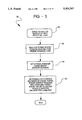
- FIG. 4 is a simplified flow chart of the basic steps performed by the preferred method of the present invention showing the optional step of monitoring the engine speed and generating the engine speed signal by which the sensed turbo boost pressure can be further modified to compensate for decreasing boost pressure when the engine rpm drops due to the engine lugging down from excessive load;
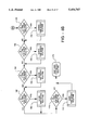
- FIG. 5 is a flow chart of the main loop of the software program used to implement the preferred method of the present invention.
- FIG. 6 is a flow chart of an interrupt routine which is used to read the channels of the A/D converter and to test the solenoids of the transmission for shorted coils;
- FIG. 7 is a flow chart of the steps implemented to check the solenoid coils for faults and to generate the driver output signals for the solenoid coils which need to be energized at a given time;
- FIG. 8 is composed of FIG. 8A and 8B and is a flow chart of the 16 ms time based routine showing the various operations that are performed to check the various sensors of the system of FIG. 1;
- FIG. 9 is a flow chart of the turbo boost process routine for determining a compensated turbo boost value which takes into account the engine speed of the vehicle;
- FIG. 10 is an exemplary listing of the boost multipliers which may be applied at various engine speeds to compensate for the dropping boost pressure that would be experienced as the engine begins to lug down in response to an external load;
- FIG. 11 is composed of FIGS. 11A and 11B and is a flow chart of the steps performed in the shift control routine of the present invention
- FIG. 12 is a flow chart showing the steps performed in the shift timing profile routine which is used to determine the appropriate PWM duty cycle and time interval for the percentage of full-load being experienced by the engine when making a shift involving directional clutches F1 or F2;
- FIG. 13 is a detailed flow chart of the boost calibration subroutine described in simplified form in FIG. 3, which is used to determine a boost offset value for producing a normalized turbo boost value to compensate for vehicle to vehicle variations in turbo boost sensor readings;
- FIG. 14 is a pair of graphs of the pressure over time to the clutches F1 and F2 illustrating the rate of engagement of these clutches under a no-load condition
- FIG. 15 is a graph of the pressure over time used to modulate the F1 and F2 directional clutches illustrating their respective rates of engagement under a full-load condition
- FIG. 16 is a graph of the pressure over time applied to the F2 clutch while up-shifting from gear 10F to gear 11F under a no-load condition
- FIG. 17 is a graph of the pressure over time applied to the F2 clutch during upshifting from gear 17F to gear 18F under a no-load condition
- FIG. 18 is a graph of the pressure over time applied by the F2 clutch during downshifting from gear with 11F to gear 10F under a no-load condition.
- FIG. 19 is a graph of the pressure over time applied to the F2 clutch during a downshift from gear 18F to gear 17F under a no-load condition.
- the system 10 generally includes an electronic controller 12 having an internal analog-to-digital (A/D) converter 14, an internal random access memory (RAM) 16, and an internal, programmable erasable, read only memory (EEPROM) 18.
- A/D analog-to-digital
- RAM random access memory
- EEPROM programmable erasable, read only memory
- a turbo boost pressure sensor 20 is coupled to an input port of the controller 12 as is a conventional engine speed sensor 22.
- the turbo boost pressure sensor is used to measure the boost pressure developed by a turbocharger associated with an engine 19 of the vehicle and preferably produces about 1.5 volts at 100 kPa, and 3.5 volts at 200 kPa.
- the engine speed sensor 22 is preferably a variable reluctance magnetic pick-up (VRMP) sensor which monitors a gear on the input shaft of a powershift transmission 23, whose speed is representative of the input shaft of the powershift transmission 23 of the vehicle. In the preferred embodiment the VRMP sensor 22 monitors a gear having 42 equally spaced teeth.
- VRMP variable reluctance magnetic pick-up
- the controller 12 divides the signal generated by the sensor 22 by a factor of 16, giving the controller 12 a signal of 2.625 pulses per revolution. This provides a signal equivalent to about 0.04375 Hz per rpm.
- An output shaft speed sensor 41 is also included which also is in the form of a VRMP type sensor. This sensor preferably monitors the speed of a gear having 72 approximately spaced teeth and provides a signal equivalent to 1.2 Hz/rpm.
- a true ground speed sensor such as a radar horn 40, may be included to provide an indication of true vehicle ground speed.
- the system 10 further preferably includes external inching clutch pedal position sensor 26 for an inching clutch pedal 26a, a top-of-clutch position switch 27a, a bottom-of-clutch pedal position switch 27b, a neutral detection sensor 28, a display/keyboard 29 mounted within the vehicle interior and a coil temperature sensor 30.
- Coil temperature sensor 30 is associated with a modulated proportional valve MC1, indicated by reference numeral 34, whose temperature is assumed to be approximately equal to a second modulated proportional valve MC2, designated by reference numeral 35.
- the temperature sensor 30 is a thermistor which provides a voltage signal indicative of the temperatures of the solenoid coils of valves MC1 and MC2.
- the controller 12 is further responsive to a shift control lever 36 for selecting various gear ratios of the powershift transmission 23, as well as directional modes of operation (i.e., either forward or reverse).
- the controller 12 is represented by a Motorola 68HC11E1 microprocessor which is operated in its expanded mode.
- a Funk 8000 series powershift transmission which is manufactured by the Funk Corporation of Coffeyville, Kans.
- This particular model of transmission provides 18 forward and 9 reverse gear ratios which are selected by engaging combinations of hydraulic clutches via solenoid control.
- the clutches are divided into three groups of three clutches, identified as "number” clutches 1, 2 and 3, "letter” clutches A, B and C, and "directional” clutches F1, F2 and R.
- the desired gear ratio is selected by engaging one clutch from each group.
- the directional clutches F1 and F2 are involved whenever a shift from gear 9F to gear 10F or gear 10F to gear 9F is commanded.
- the R directional clutch is involved when shifting from neutral to any reverse gear.
- Clutch F1 is involved when shifting from neutral to gears 1F-9F.
- Clutch F2 is involved when shifting into any of gears 10F-18F.
- Each of the nine clutches further has an "on/off" solenoid which allows the clutch to engage when power is applied.
- the modulated proportional valves 34 and 36 shown in simplified form in FIG. 1 are used to control the pressure to the directional clutches F1, F2 and R.
- Valve MC1 controls pressure to the F1 directional clutch while proportionally modulatable valve MC2 controls pressure to both the F2 and R directional clutches.
- Valves MC1 and MC2 cause decreasing clutch pressure with increasing current and are ideally suited for use with pulse-width-modulated (PWM) current drive signals generated by the controller 12.
- PWM pulse-width-modulated
- the preferred methods of the present invention incorporate the use of predetermined shift modulation profiles for no-load and full-load shifts.
- the no-load and full-load shift modulation profiles each represent a "pressure vs. time" shift profile which is intended to bring the involved on-coming clutch into engagement at a predetermined rate of engagement.
- the full-load and no-load shift modulation profiles are used by the controller 12 to generate PWM drive signals each having a suitable duty cycle, for a suitable time, to produce the desired pressure vs. time shift profile.
- the controller 12 when a full-load shift is desired, for example, the controller 12 generates a PWM signal having a duty cycle sufficient to modulate the on-coming directional clutch (i.e., clutch F1 or F2) into engagement at the desired rate of engagement, for the desired time period, to match the predetermined full-load pressure vs. time curve.
- the PWM signal controls the rate at which the proportional solenoid valve being modulated (i.e., either valve MC1 or MC2) is opened, for a specific, predetermined time period, to accomplish the full-load shift.
- the steps used to determine the full-load and no-load shift modulation profiles are presented. Initially, the vehicle is driven on a level surface, and preferably a concrete surface to minimize the drag on the vehicle, until a wide open throttle (WOT) condition is achieved, as indicated at step 44. Next, the turbo boost pressure reading (i.e., value) from the turbo boost pressure sensor 20 is recorded under a no-load condition, as indicated at step 46. At step 48, the appropriate no-load shift modulation profile is determined to provide a desired rate of engagement for any one of the directional clutches when a shift is commanded under a no-load condition.
- WOT wide open throttle
- Such a shift is preferably one which takes place rapidly but without vehicle jolt or lurch.
- a drawbar load is then attached to the vehicle which is sufficient to cause the engine speed at wide open throttle to drop to "rated" engine speed for the particular engine being used.
- the rated engine speed of an engine is understood to mean that engine speed which causes the engine to produce its peak torque.
- step 50 the turbo boost pressure from the turbo boost pressure sensor 20 is recorded, which represents the boost pressure value under a full-load condition.
- step 54 an appropriate shift modulation profile (i.e., pressure vs. time) curve is determined to produce a desired rate of engagement for a shift made under a full-load condition.
- an appropriate duty cycle and time period will be determined, through repeated experimentation, which cause the on-coming directional clutch to engage at a rate of engagement and within a desired time.
- This rate of engagement and time period will be such as to produce a shift which is rapid enough to prevent the engine rpm from dropping appreciably while the shift is being executed, to thereby produce a smooth shift without sudden vehicle deceleration.
- the turbo boost pressure increases linearly with the load being experienced by the engine.
- the pressure vs. time shift modulation profile is modified (i.e., reduced) by the percent value of full-load which the boost pressure signal from the pressure sensor 20 is indicating. For example, if the boost pressure sensor 20 is generating a boost pressure signal which is approximately 50% of the boost pressure signal which is generated under full load, then it is assumed that the load being experienced by the engine is approximately half of that which would be experienced under full-load.
- the PWM duty cycle is then modified by the controller 12 to produce a pressure versus time shift modulation profile which causes the appropriate on-coming directional clutch to engage at a rate of engagement, for an appropriate time period, which is approximately 50% of that rate at which it would engage if under a full-load condition, and for approximately half the predetermined full-load time period.
- a duty cycle would be generated which causes the appropriate on-coming clutch to engage at a rate of engagement, and for a time period, which are approximately 75% that of the rate and time that would be utilized under a full-load shift condition.
- the load at which the engine is operating under at any given time can then be sensed through the instantaneous boost pressure if that boost pressure signal is rationalized as a percentage of the full-load boost pressure signal.
- the turbo boost pressure generated can thus be utilized to provide a very good indication of the load at which the engine is operating under and, therefore, the rapidness of the shift which should be executed to prevent unwanted vehicle lurch, jolt or sudden deceleration.
- the turbo boost sensor 20 (FIG. 1) is calibrated preferably "on-vehicle". Referring to FIG. 3, this procedure is shown in simplified form in connection with flow chart 55. A more detailed explanation of this calibration procedure will be provided in connection with the flow chart of FIG. 9.
- the vehicle is driven on a level surface under a full-throttle, no-load condition in gear 9F, as indicated at step 56.
- the turbo boost sensor 20 is then monitored for a predetermined time, for example, preferably about three seconds, as indicated at step 58. Multiple readings of the turbo boost sensor 20 are taken during this time period.
- an "average" turbo boost sensor reading is determined, as indicated at step 60, from the multiple readings obtained at step 58.
- the difference between a predetermined “baseline” turbo boost value and the average turbo boost sensor reading is determined, as indicated at step 62, which represents the variation of the average turbo boost sensor reading from the predetermined, baseline value.
- This difference i.e., offset
- the controller 12 monitors the turbo boost pressure from the boost sensor 20 and generates a turbo boost signal indicative of the boost pressure being developed by the turbocharger of the vehicle engine, as indicated at step 64.
- an engine speed signal is read from the engine speed sensor 22 (FIG. 1), as indicated at step 66.
- Step 66 is optional but preferred in view of the fact that the turbo boost pressure typically falls off slightly when the engine is operated under load conditions which exceed the peak torque output of the engine. Put differently, as the load on the engine increases, a point will be reached where the engine is producing peak torque, which will also represent the maximum boost pressure generated by the turbocharger.
- the controller 12 determines if a shift involving directional clutch F1, F2 or R has been commanded by the operator, as indicated at step 68. If not, the turbo boost pressure signal and engine speed signal are updated, as indicated at steps 64 and 66. If so, the controller 12 determines the appropriate shift modulation profile, as indicated at step 70, based on the sensed turbo boost signal and the engine speed signal.
- the controller 12 determines from a look-up table stored in its internal ROM an appropriate engine speed "constant" value which compensates for the drop in turbo boost which would occur if the engine speed has begun to drop.
- the monitored turbo boost signal is multiplied by the engine speed constant to keep the turbo boost signal from dropping and thereby erroneously indicating to the controller 12 that the load of the vehicle is decreasing, when in fact the load is increasing. This will be explained more fully in connection with the flow chart of FIG. 9.
- the controller 12 generates the PWM drive signal with an appropriate duty cycle, for an appropriate time, in accordance with the shift modulation profile (either full-load or no-load) for the appropriate directional clutch. This then causes the appropriate directional clutch to be modulated into engagement at the appropriate rate of engagement depending upon the vehicle load.
- the turbo boost pressure being generated at a given time and the engine speed of the vehicle at the same time, a very good approximation of the engine load can be determined, which can then be used to determine the appropriate rate of engagement of the on-coming directional clutch when a shift is made.
- turbo boost pressure is assumed to represent purely drawbar load
- the methods described herein could readily be modified by those skilled in the art to avoid compensating for load imposed on the engine by a power take-off (PTO).
- PTO power take-off
- a suitable torque sensor is used to monitor the torque of the PTO and by factoring in the sensed PTO torque, at a given time, into the sensed turbo boost pressure value.
- FIGS. 5-12 the detailed operation of the preferred methods of the present invention will be discussed.
- FIG. 5 thus represents one complete cycle which is performed by the controller 12, which will be referred to hereafter as the microprocessor 12.
- the execution time of the steps illustrated in FIG. 5 rarely exceeds 4 ms, and many times is less than 1 ms.
- the first step is the execution of a "reset initialize" routine, as indicated at step 74.
- the registers of the microprocessor 12 are configured as required.
- the outputs of the microprocessor 12 are configured to an initial reset state.
- the interrupts of the microprocessor 12 are disabled, but the interrupt masks are configured as desired.
- the checksum of the operational code associated with the software of the present invention is calculated and verified to ensure no memory upsets have occurred. If the checksum fails, the microprocessor 12 will not execute any additional software code.
- the internal microprocessor RAM 16 is tested and set to zero. If any of the RAM tests fail, the microprocessor 12 will not execute any additional software code. Further necessary information is retrieved from the microprocessor's internal EEPROM 18. This information includes the maximum forward gear desired (for example, 18 when using the Funk 8000 series transmission), vehicle specific clutch calibration values for F1, F2 and R clutches, the inching pedal position sensor 26 minimum and maximum voltage readings, and the turbo boost sensor 20 calibration values. All fault codes are also cleared. The microprocessor's internal EEPROM-based CONFIG register is checked to ensure proper operation of the controller. If the CONFIG register is not correct, the software of the invention will attempt to reprogram this register, and program execution will continue. The internal timers are configured as required and the interrupts are enabled as configured. The transmission of the vehicle is set to neutral and the default forward and reverse gears are initialized as desired. In the preferred embodiment the default forward gear is sixth gear and the default reverse gear is third gear reverse.
- step 76 the software begins executing the steps of the main loop, which comprises steps 76-100.
- the microprocessor's 12 internal watchdog timer is serviced.
- the watchdog service messages are stored in two RAM locations which are initialized in the reset initialize routine (step 74).
- the first watchdog service byte is written to the watchdog at the beginning of the main loop.
- the second message is written at step 100, at the end of the main loop.
- step 78 the microprocessor 12 reads the port coupled to the optional radar horn 40, if such a device is being used. This provides a true ground speed signal to the microprocessor 12 should same be desirable for any purpose. It will be appreciated, however, that this step is optional and is not essential to the main loop.
- the speed of the output shaft of the powershift transmission is determined by reading the port coupled to the output shaft speed sensor 41.
- the signal of the output shaft speed sensor which is a VRMP sensor, is equivalent to about 1.2 Hz per rpm. Approximate wheel speed is calculated by assuming that at about 151.48 rpm the vehicle is traveling at 1.0 mph. Those skilled in the art will appreciate, however, that wheel size will affect this calculation as will tire wear.
- the input shaft speed is calculated and filtered. This is accomplished by the microprocessor 12 reading the port coupled to the input shaft VRMP (i.e, engine speed sensor 22).
- an inquiry is made to determine if a 5 ms timer started immediately after the reset initialize routine (step 74) has expired. If so, a 5 ms time-based routine is executed, as indicated at step 86 before the next step in the main loop is executed.
- the 5 ms time-based routine will be described in greater detail momentarily. Essentially, however, this routine involves performing certain diagnostics, updating the values from the microprocessor's 12 internal A/D converter 14 and checking for various faults of any of the output drivers or solenoids.
- the software checks to determine if a 16 ms timer configured in software has expired, as indicated at step 88. This timer is also started immediately after the reset initialize routine (step 74). If the 16 ms timer has expired, a 16 ms time-based routine is executed, as indicated at step 90. Briefly, this routine involves checking and updating a number of operational parameters involving the present state of switches which indicate the position of the shift lever 36 (i.e., what gear ratio and directional mode is commanded), performing engine speed compensation calculations involving the engine speed compensation values, scaling the turbo boost sensor reading based on the turbo boost calibration value, and other operations. This routine will also be discussed in more detail momentarily.
- the digital switch inputs of the microprocessor 12 are sampled and the results are used to determine when any switch associated with the shift lever 36 has changed state and has been debounced in a separate time-based debounce loop, as indicated at step 90.
- the specifics of this debounce loop are disclosed in co-pending U.S. application Ser. No. 08/077,572, filed on Jun. 15, 1993, and entitled GEARSHIFT MECHANISM. This application is hereby incorporated by reference.
- the serial communications interface port is polled by the microprocessor 12 to see if a message has been received thereat by any external device in communication with the microprocessor 12. If it has, the message request is processed, a response message is formed, and the transmission of the response is initiated, all as indicated at step 94.
- the microprocessor 12 since the microprocessor 12 is afforded the capability of serial communications, the microprocessor 12 can be interfaced with an external development tool should one wish to reprogram any of the stored constants, such as the engine speed compensation values, should this be desirable.
- a micro self-diagnostic routine is executed which refreshes the control registers and performs various tests on the RAM of the system, in addition to performing other routine tests for the microprocessor 12.
- the microprocessor 12 is required to service an external watchdog. Essentially, the microprocessor 12 is required to toggle an output port thereof within approximately 16 ms to prevent an external watchdog timer from resetting the microprocessor 12.
- the second service message is written at the end of the main loop as explained hereinbefore.
- an interrupt routine 102 which is labelled the "OC5 interrupt”. This interrupt occurs every 1 ms, as indicated at step 104. Immediately after the interrupt occurs, the OC5 interrupt flag is cleared, as indicated at step 106, and the internal A/D converter 14 channels are read and the results thereof stored in the RAM 16 of the microprocessor 12 (FIG. 1), as indicated at step 108. Next, the solenoid drivers which are currently "on” are tested to determine if the coil of the solenoid associated therewith is shorted, as indicated at step 110. Approximately 1 ms later, and every 1 ms thereafter, this routine is repeated.
- the 5 ms time-based routine indicated at step 86 in FIG. 5 is shown in more detail.
- the first step in this routine involves checking to determine if a 0.5 second delay after powerup has passed, as indicated at step 112. If not, this routine is terminated, as indicated at step 114. If the 0.5 second delay has occurred, a shift control routine is executed, as indicated at step 116. This routine essentially involves setting up and handling all of the solenoid patterns and duty cycles required to implement a shift and to maintain (i.e., refresh) the solenoids and duty cycles needed to maintain operation in the currently selected gear.
- a driver diagnostic subroutine is executed, as indicated at step 118, which checks to determine if the solenoid drivers that need to be turned on to effect a shift are in fact functional (i.e., not shorted or open).
- An output driver/coil fault subroutine is executed next, as indicated at step 120, which analyzes any faults determined to exist at step 118.
- the subroutine of step 120 also attempts to pick a gear which is closest to the desired gear commanded by the operator which cannot be used because of a fault with a component associated therewith.
- a driver output routine is executed which causes the appropriate currents to be applied to the solenoids to be turned on to either implement a shift or maintain operation in a desired gear.
- the 16 ms time based routine which is executed at step 90 of the main loop shown in FIG. 5 is set forth in detail in FIGS. 8A and 8B.
- a power-up delay flag process routine is executed to ensure that a minimum predetermined time has elapsed after power, such as, for example, a 500 ms delay.
- the clutch calibration values are stored in EEPROM 18 of the microprocessor 12 for the modulated clutches F1, F2 and R. These values represent the current offset values needed to just begin to cause clutch engagement.
- the vehicle-specific turbo boost calibration values are all stored in EEPROM 18.
- the vehicle-specific boost calibration constant (i.e., boost offset value) determined as explained in connection with FIG. 3 is stored in EEPROM 18 of the microprocessor 12.
- an EEPROM service subroutine is executed to ensure that any values which need to be written to or read from the EEPROM 18 are valid.
- Step 132 represents an optional feature by which additional clutch calibration information in the form of an offset value can be added, for example, by trained service technicians, to further modify the shift characteristics of any one of the directional clutches.
- an "on-off hold timer” is incremented which essentially keeps track of how long the coils of the solenoid valves associated with each of the on/off clutches of the transmission are being held at 12 volts.
- the on/off solenoid valves each include six volt coils. However, a 12 volt DC signal is applied to each coil when it is turned on to drive the solenoid very quickly into its on position.
- the on/off hold timer at step 134 keeps track of how long a particular solenoid is being held at +12 volts DC. This timer is also cleared when a +12 volt DC signal is first applied to any on/off solenoid valve. The timer is incremented approximately every 16.3 ms.
- a shift lever control process routine is executed which reads the switches associated with the gearshift lever 36 which indicate the position of the lever 36.
- This routine is explained in greater detail in U.S. application Ser. No. 08/077,572, now U.S. Pat. No. 5,388,476. It will be appreciated, however, that the routine explained in detail in U.S. application Ser. No. 08/077,572, is not essential to proper operation of the present invention but is preferably included at this point in the 16 ms time based routine 90.
- an engine speed compensation calculation routine is executed which modifies the duty cycle of the modulated clutches F1 and F2 based on the engine speed. This compensates for the lower hydraulic pump pressure which is generated at lower engine speeds.
- an analog filtering routine is executed which filters analog voltages from the turbo boost sensor 20, the inching clutch pedal sensor 26 voltage, the feedback voltages obtained from any diagnostic sensors, and the system voltage.
- a fault control routine is executed for handling other faults that are not related to the output drivers for the solenoid valves. For example, this routine checks to ensure that the inching clutch pedal sensor 26 is not shorted to ground, that the turbo boost sensor is not shorted to ground, or that the output shaft speed sensor 41 is not malfunctioning.
- a switch transition mode control routine is executed, as indicated at step 144, to ensure that the voltage signal from the top-of-clutch switch 27a is within acceptable limits, that if a bottom-of-clutch signal from bottom-of-clutch switch 27b is being generated that that signal is within acceptable voltage limits, and that the inching pedal potentiometer 26 (FIG. 1) is operating within valid voltage limits.
- a frequency input overflow routine is executed to set the input shaft or output shaft speeds to zero when no pulses are received by the VRMP sensor associated with each of the input and output sensors 22 and 41, respectively, and when the frequency of the pulses from each sensor falls below a predetermined lower limit.
- a turbo boost process routine is executed. This routine is described in greater detail with the flow chart of FIG. 9, but essentially involves scaling the turbo boost value provided by the turbo boost sensor 20 in relation to the engine rpm to compensate for the drop in turbo boost pressure that occurs when the engine is operated at high loads which cause the engine to lug down.
- an inching pedal process routine is executed to determine the duty cycle that needs to be applied to the directional clutch F1 or F2 being engaged via the clutch pedal by the operator to produce the appropriate clutch pressure based on the current pedal position. Thus, this routine determines the proper duty cycle which corresponds to the clutch pedal position at a given instant.
- a shorted output diagnostic routine is executed. This routine involves sampling the voltages of energized solenoid coils every 5 ms. With every 16 ms period there will be then at least three samples taken from which it will be determined if a coil which is energized is actually shorted. If any coil is shorted, its voltage will fall below a predetermined lower limit. A diagnostic fault indication can then be provided to a display panel of the vehicle to provide an operator that a fault condition has arisen.
- step 154 every 1048.576 ms, the software processes certain information and performs certain fault condition checks, to be explained momentarily.
- a check is made to determine if 1049 ms has elapsed. If so, a 1048 ms time based routine is executed.
- This routine processes an audio alarm signal which is present for about three seconds during the turbo boost calibration mode. This alarm is generated in response to an operator pressing appropriate switches on the display/keyboard 29 for a period greater than three seconds while the tractor is on a smooth level surface with its throttle at high idle and the shift lever 36 in neutral.
- routine at step 168 has been performed or the test at step 166 proves false, then a check is made to determine if 66 ms has elapsed, as indicated at step 170. If this test proves true, then a 66 ms time based routine is executed as indicated at step 172. With this routine, every 65.536 ms the inching pedal diagnostics are executed together with the input and output shaft speed sensor diagnostics. Once this routine has been concluded, or the test at step 170 proves false, the 16 ms time based routine ends, as indicated at step 174.
- the turbo boost process routine executed at step 148 in FIG. 8 is shown in greater detail.
- the software determines if the system is in the boost calibration mode, as indicated at step 176.
- the boost calibration mode is preferably initiated via a display mounted control. If the calibration mode has been selected by the operator or a service technician, then the boost calibration subroutine (routine 55 of FIG. 3) is executed, as indicated at step 177.
- the sensed turbo boost value which now represents a "normalized” value after being modified by the vehicle specific calibration constant, is further modified by multiplying it by an appropriate one of a plurality of engine speed constants.
- the engine speed constants are stored in a look-up table, as indicated at step 182, and compensate for situations where the engine has begun to "lug down", thus causing the turbo boost pressure value sensed by the sensor 20 (FIG. 1) to drop.
- the boost signal sensed by the sensor 20 increases, it is assumed linearly, as engine rpm increases. However, when the load on the vehicle becomes so great such that the engine begins to lug down, the dropping engine rpm will cause a reduction in the boost pressure generated by the engine's turbocharger.
- the microprocessor 12 would determine, erroneously, that the load is dropping when in fact the load is actually increasing on the vehicle. Thus, the microprocessor 12 would determine that the vehicle is more lightly loaded and cause the improper duty cycle to be used for the PWM drive signal used to modulate the appropriate clutch into engagement.
- the drop in turbo boost pressure that occurs as the engine begins to lug down is compensated for.
- the multiplier for the turbo boost value below 2100 rpm increases as the engine rpm decreases. In this example, 2100 rpm represents the engine speed at which the engine produces its peak torque under full-load. As the engine begins to lug down due to an external load on the vehicle, the value of the boost multiplier increases.
- the normalized boost pressure value is multiplied by the engine speed constant to achieve a "conditioned" turbo boost value.
- step 186 in FIG. 11A a check is made to determine if the output power-up diagnostics have been performed. These diagnostics involve having the microprocessor 12 briefly turn on each solenoid valve, one at a time, to ensure that there are no shorted control lines going to the coils of each of the solenoid valves. It will be noted that energizing one solenoid valve at a time with the Funk 8000 series transmission will not cause any shifting to occur.
- the solenoids are actually turned on, one at a time, with appropriate drive signals from the microprocessor 12, if the output power-up diagnostics have not previously been performed.
- the powershift ratio is determined by dividing the sensed output shaft speed by the sensed input shaft speed.
- a ground speed matching routine is executed. This routine is implemented to avoid any possible damage to the directional clutches when a shift is commanded by the operator to a gear ratio which differs by more than one gear from the gear ratio the transmission is presently in.
- this routine will cause the powershift transmission 23 to first shift into the gear which is closest in ratio to the gear ratio which the transmission was previously in. This ensures that the shifting between widely varying gear ratios will not cause unnecessary lurching or jolting of the vehicle or damage to the directional clutches of the transmission 23.
- a check is next made to determine if the transmission is in neutral. This is accomplished by determining if either the operator has the clutch pedal 26 depressed completely such that the bottom-of-clutch pedal sensor 27b is indicating same or the shift lever 36 of the transmission 23 has been placed in neutral, as detected by the neutral detection switch 28. If the transmission is detected to be in neutral, a shift timer is set to zero, a neutral shift timer is set to zero and a neutral timer is incremented, all as indicated at step 196. Subsequently, a neutral subroutine is executed, as indicated at step 198, to place the transmission 23 in neutral.
- step 194 if the transmission 23 is not detected to be in neutral, as checked at step 194, the neutral shift timer is incremented by one, the shift timer is also incremented by one and the neutral timer is set to zero, as indicated at step 200. This step essentially keeps track of how long the shift lever 36 has been out of the neutral position.
- step 202 a check is made to determine if the current gear is neutral and, if so, a neutral shift is executed as indicated at step 204. If the current gear is not set to neutral, a check is made to determine if the current gear is equal to the gear requested, as indicated at step 206.
- step 206 if the test at step 206 is determined to be false, then a check is made to determine if the shift that has been commanded by the operator is either from one forward gear to another forward gear or from one reverse gear to another reverse gear, as indicated at step 210. If this test proves false, then it is determined that a shift into neutral has been commanded and the neutral shift subroutine is executed, as indicated at step 212. It will be appreciated that this is the same neutral shift subroutine that would have been commanded at step 198 had it been determined at step 194 that the transmission was in neutral.
- step 210 If the test at step 210 indicates that either a shift from one forward gear to another has been commanded or a shift from one reverse gear to another reverse gear has been commanded, a check is made to determine if the commanded shift is already in progress, as indicated at step 214. If so, the microprocessor 12 determines the appropriate PWM duty cycles and solenoid actuation patterns based on how far the controller is into executing the shift, as all indicated at step 216. Subsequently, at step 217 the inching clutch pedal sensor 26 is checked by the microprocessor 12 and if this pedal is being engaged by the operator the microprocessor 12 uses the signal generated by the sensor 26 to override the PWM drive signal which would normally be applied to modulate the involved directional clutch into engagement to complete the shift. Thus, the operator is always afforded the capability of overriding the modulation signal that would be applied to the involved directional clutch if a condition exists where an even slower or more rapid clutch engagement is desired than what would otherwise be commanded by the microprocessor 12.
- step 214 if it is determined that no shift is already in progress, then the shift timer is set equal to zero, as indicated at step 218, and the appropriate PWM drive signal is determined based on the compensated turbo boost value, as indicated at step 220 which is called the calculated shift timing profile routine.
- the turbo boost shift timing profile routine executed at step 220 in FIG. 11 is shown in greater detail.
- Tnorm no-load normalized turbo boost value under no-load
- Tnorm full-load normalized turbo boost value under full-load.
- the calculation at step 222 determines what percent of full-load the engine is experiencing by comparing the compensated turbo boost value with the predetermined full-load and no-load normalized turbo boost values.
- the microprocessor 12 can determine what percent of full-load the engine is experiencing at any given time based on the compensated turbo boost value determined at the time and the known no-load and full-load turbo boost values.
- the microprocessor 12 determines that the transmission has been in neutral for at least a predetermined time. If this test proves true then it is determined that the transmission has not just been shifted out of neutral and that any load being experienced by the engine is due to static drawbar load (i.e., not dynamic load). If this test proves false then it is assumed that the vehicle is accelerating from a stand still and that the load being experienced by the engine is simply that load which is experienced in simply getting the vehicle up to the desired speed. In this instance, as indicated at step 226, it is assumed that the true boost percent is one-half of the boost percentage value calculated at step 222.
- step 228 the desired time value in which the shift is to be completed is determined based on either the boost percentage value calculated at step 222 or the modified value determined at step 226. This is accomplished by the following formula:
- step 230 the appropriate duty cycle for the PWM drive signal is determined. This determination is made in accordance with the following formula:
- step 230 determines what duty cycle is required to bring the on-coming directional clutch into complete engagement in the time period determined at step 228. Together, steps 228 and 230 determine the appropriate percentage of the full-load pressure and full-load time values that need to be used to generate the PWM drive signal for modulating the on-coming directional clutch into engagement in accordance with the load being experienced by the engine, as indicated by the compensated turbo boost value. Thus, if the compensated turbo boost value is 50% of that which would be sensed if the engine was operating under a full-load condition, then 50% of the full-load pressure and full-load time values would be used to generate the PWM drive signal.
- the top graph 232 represents the pressure to the off-going directional clutch F1 overtime during a shift from gear 9F to gear 10F, as indicated by curve 232a, and a shift from gear 10F to gear 9F as indicated by curve 232b.
- the bottom waveform 234 indicates the pressure produced to modulate the directional clutch F2 when this clutch comes on, as indicated at waveform portion 234a during a shift from gear 9F to gear 10F.
- Portion 234b of this waveform indicates the rapid fall off in pressure to the off-going F2 directional clutch when a shift from gear 10F to gear 9F is made.
- the graphs of FIG. 14 represent the performance of the F1 and F2 directional clutches with an engine of the vehicle operating at approximately 2520 rpm under a no-load condition.
- the pressure waveform for off-going directional clutch F1 is shown by waveform 236 and the pressure applied to on-coming clutch F2 is shown by waveform 238.
- the engine rpm is at 2400 with the engine fully loaded.
- Portion 236a of waveform 236 and portion 238a of waveform 238 indicate the pressure applied to these two directional clutches during a shift from gear 9F to gear 10F.
- portion 236b of waveform 236 and portion 238b of waveform 238 indicate the pressures to the directional clutches F1 and F2 during a shift from gear 10F to gear 9F.
- step 240 a check is made, as indicated at step 240, to determine if the transmission is in gear 9F. If not, the boost calibration mode is exited and the previous boost calibration value is used for subsequent determinations of the appropriate PWM duty cycle based on the previously sensed turbo boost signal, as indicated at step 242. If the test at step 240 proves true, a check is made to determine if the boost calibration is already in progress, as indicated at step 244. If this test proves false, a check is made to determine if a boost calibration switch on the display panel within the vehicle has been pressed by the operator, as indicated at step 246. If this test proves true, then a boost calibration timer is set equal to zero, as indicated at step 248, and the routine ends at step 264.
- step 246 If the test at step 246 proves false (i.e., the boost calibration switch has not been pressed), then the boost calibration mode is exited at step 242. If the test at step 244 proves true, then a check is made to determine if the clutch pedal position is greater than 90% engaged, as indicated at step 250. If this test proves false then the microprocessor 12 determines that the clutch pedal is presently engaged by the operator and the boost calibration mode is exited. If the test at step 250 proves true, however, then the engine speed is checked to determine if it is greater than approximately 2250 rpm, as indicated at step 252. If this test proves false, then the microprocessor 12 determines that the engine is not operating at wide-open-throttle and again exits the boost calibration mode.
- step 254 determines if the vehicle speed is greater than about 4.5 mph. This test ensures that the vehicle is traveling at at least a minimum predetermined speed that should be attainable under a no-load condition when in gear 9F. If this test proves false then the microprocessor 12 determines that the calibration cannot be accurately performed and exits the boost calibration mode. If the test proves true, then the boost calibration timer is incremented by a factor of 16 ms, as indicated at step 256, and a check is then made at step 258 to determine if three seconds has elapsed since the boost calibration mode has been entered.
- a boost offset value is determined by subtracting the actual boost value determined from the baseline turbo boost value under a no-load condition, as indicated at step 260. If the test at step 258 proves true, then the last offset value determined at step 260 is stored at step 262 in the RAM 16 of the microprocessor 12. The boost calibration routine is then terminated, as indicated at step 264.
- the preferred methods of the present invention are also applied during upshifts and downshifts between forward gears 10F-18F.
- a calibration procedure is undertaken which is identical in form to that shown in FIG. 2 to determine a suitable percentage of reduction in the pressure of directional clutch F2 when upshifts or downshifts are made from one gear to another between gears 10F and 18F while the vehicle is under no-load, and a suitable percentage reduction in the pressure of clutch F2 when the vehicle is under full load during upshifts or downshifts between gears 10F-18F.
- a percentage in the reduction of the pressure applied by the F2 clutch is determined for both a no-load condition and a full-load condition, along with a suitable time value during which the pressure of the F2 clutch is brought back up so as to fully engage the F2 clutch.
- the presently preferred value in the reduction of pressure of the F2 clutch during upshifts and downshifts under no-load, between gears 10F-18F, is about 80 percent.
- the pressure to the F2 clutch is reduced preferably by about 80 percent when making any upshift or downshift between gears 10F-18F.
- a waveform 266 illustrates the pressure of the F2 directional clutch during an upshift between gears 10F-11F.
- the pressure to the F2 clutch drops off very rapidly (almost instantaneously) by about 80 percent to almost completely disengage the F2 clutch during the upshift. This amount of pressure reduction is, in any event, sufficient to "break" the transmission of torque to the output shaft of the transmission.
- the pressure is then ramped up in accordance with the determined boost percent value (the procedure of which is described in connection with FIG. 12).
- the boost percent value determines the duty cycle for the PWM drive signal applied to the F2 clutch as well as the time interval in which to bring the F2 clutch back into full engagement.
- portion 266c of waveform 266 after the time represented by the time interval 266d, full pressure is thereafter applied by the F2 clutch.
- the methods described herein are not only used to control modulation of the F1 and F2 clutches during shifts between gears 9F and 10F, but also during upshifts between gears 10F and 18F.
- FIG. 17 an upshift between gears 17F and 18F is shown.
- the pressure of the F2 clutch is denoted by waveform 268.
- the pressure of the F2 clutch is reduced by about 80 percent, as indicated by portion 268a of waveform 268, to almost completely disengage the F2 clutch during the upshift.
- the pressure of the F2 clutch is ramped up, as indicated by portion 268b of the waveform 268, until full pressure is again being applied by the F2 clutch, as indicated at portion 268c of the waveform 268.
- time duration as denoted by time interval 268d, is longer than that for the upshift between gears 10F and 11F.
- the shift is accomplished by modulating the F2 clutch back into full engagement at a rate, and over a time interval, which provides a relatively smooth shift, and which avoids an undesirable jolt or lurch of the vehicle. Accordingly, the pressure to the F2 clutch is ramped up much more gradually during an upshift between gears 17F and 18F than it is between gears 10F and 11F.
- waveform 270 the pressure applied to the F2 clutch during a downshift from gear 11F to gear 10F is shown by waveform 270.
- waveform 270a denotes a reduction of about 80 percent in the pressure applied by the F2 clutch to almost immediately cause the F2 clutch to become almost completely disengaged.
- Portion 270b illustrates the pressure being ramped up in accordance with the PWM duty cycle and time interval determined by the calculated boost percent value until full pressure is again being applied by the F2 clutch, as indicated by portion 270c of the waveform 270.
- the time interval represented by period 270d reflects the total time taken to bring the pressure of the F2 clutch back up to full pressure.
- portion 272a indicates a drop of about 80 percent in the pressure of the F2 clutch as the downshift begins. Thereafter, the pressure of the F2 clutch is ramped up, as indicated by portion 272b of the waveform 272, to bring the pressure of the F2 clutch back to full pressure, as indicated by portion 272c.
- the time interval indicated by portion 272d is greater than that for a downshift from gear 11F to gear 10F. Again, this is because the boost pressure produced at vehicle operating speeds during a shift between gears 18F and 17F is greater under a no-load condition than the boost pressure generated during a shift between gears 11F and 10F while under a no-load condition.
- the F2 directional clutch is modulated into engagement in accordance with a suitable duty cycle and over a suitable time interval to produce a smooth shift under a no-load condition. If the upshifts of FIGS. 16 and 17 were made by operating under a full-load condition, then portions 266a and 268a of each waveform 266 and 268, respectively, would be significantly shorter and would represent a drop off in the pressure applied to the F2 clutch of only a very small degree, and preferably between about 0 percent and 10 percent.
- portions 266b and 268b would be steeper to cause the time interval 266d or 268dto be significantly reduced, to thus bring the F2 clutch back up to full pressure much more quickly.
- the boost pressure value is such as to indicate a load condition at a midpoint between no-load and full-load
- the reduction and pressure illustrated by portions 266a and 268a of waveforms 266 and 268, respectively would indicate only about a 40 percent drop in the pressure of the F2 clutch.
- the time durations represented by portions 270b and 272b of waveforms 270 and 272, respectively would be steeper to illustrate more rapid increase in the rate of pressure of the F2 clutch.
Priority Applications (4)
| Application Number | Priority Date | Filing Date | Title |
|---|---|---|---|
| US08/176,021 US5454767A (en) | 1993-12-30 | 1993-12-30 | Powershift transmission control system with turbo boost monitor |
| CA002139137A CA2139137C (fr) | 1993-12-30 | 1994-12-22 | Systeme de commande de servotransmission muni d'un detecteur de suralimentation |
| EP94309911A EP0661479A1 (fr) | 1993-12-30 | 1994-12-30 | Système de commande pour transmission de changement de vitesse sous charge avec enregistrement de suralimentation |
| US08/458,965 US5778329A (en) | 1993-12-30 | 1995-06-02 | Powershift transmission system with torque-mapped shifts |
Applications Claiming Priority (1)
| Application Number | Priority Date | Filing Date | Title |
|---|---|---|---|
| US08/176,021 US5454767A (en) | 1993-12-30 | 1993-12-30 | Powershift transmission control system with turbo boost monitor |
Related Child Applications (1)
| Application Number | Title | Priority Date | Filing Date |
|---|---|---|---|
| US08/458,965 Continuation-In-Part US5778329A (en) | 1993-12-30 | 1995-06-02 | Powershift transmission system with torque-mapped shifts |
Publications (1)
| Publication Number | Publication Date |
|---|---|
| US5454767A true US5454767A (en) | 1995-10-03 |
Family
ID=22642656
Family Applications (1)
| Application Number | Title | Priority Date | Filing Date |
|---|---|---|---|
| US08/176,021 Expired - Lifetime US5454767A (en) | 1993-12-30 | 1993-12-30 | Powershift transmission control system with turbo boost monitor |
Country Status (3)
| Country | Link |
|---|---|
| US (1) | US5454767A (fr) |
| EP (1) | EP0661479A1 (fr) |
| CA (1) | CA2139137C (fr) |
Cited By (19)
| Publication number | Priority date | Publication date | Assignee | Title |
|---|---|---|---|---|
| US5778329A (en) * | 1993-12-30 | 1998-07-07 | Agco Corporation | Powershift transmission system with torque-mapped shifts |
| US6199450B1 (en) | 1999-12-17 | 2001-03-13 | Caterpillar Inc. | Method and apparatus |
| US6254511B1 (en) | 1999-10-29 | 2001-07-03 | Caterpillar Inc. | Method and apparatus for adaptively controlling clutches based on engine load |
| US20040249543A1 (en) * | 2003-06-09 | 2004-12-09 | Deere & Company, A Delaware Corporation | Load anticipating engine/transmission control system |
| US20050088465A1 (en) * | 2003-10-28 | 2005-04-28 | Parish George K. | Ink jet printer with resistance compensation circuit |
| US20050211528A1 (en) * | 2004-03-26 | 2005-09-29 | Yanming Hou | Power take-off control system and method |
| US20050217398A1 (en) * | 2004-03-26 | 2005-10-06 | Yanming Hou | Power take-off control system |
| US20050217397A1 (en) * | 2004-03-26 | 2005-10-06 | Yanming Hou | Power take-off control system |
| US20070044471A1 (en) * | 2005-08-25 | 2007-03-01 | Stephane Cochet | Internal combustion engine with power boost in response to impending load |
| US7190589B2 (en) | 2004-10-19 | 2007-03-13 | Cinch Connectors, Inc. | Electronic control enclosure |
| WO2008094115A1 (fr) * | 2007-01-31 | 2008-08-07 | Scania Cv Ab (Publ) | Procédé et système d'estimation de la charge d'un groupe d'appareils alimenté par un moteur |
| US20080228364A1 (en) * | 2007-03-16 | 2008-09-18 | Osselaere Guy H J | Method for engaging a clutch |
| US20080250786A1 (en) * | 2007-04-13 | 2008-10-16 | Robinson James S | Method for manually controlling a turbocharger |
| US20090118096A1 (en) * | 2007-11-05 | 2009-05-07 | Toyota Motor Engineering & Manufacturing North America, Inc. | Automatic transmission upshift timing |
| US20110045948A1 (en) * | 2009-08-24 | 2011-02-24 | Ford Global Technologies, Llc | Methods and systems for turbocharger control |
| JP2012128743A (ja) * | 2010-12-16 | 2012-07-05 | Nsk Ltd | スタックオーバーフローの検出方法 |
| US20150100187A1 (en) * | 2013-10-04 | 2015-04-09 | Ford Global Technologies, Llc | Method of operating an electric or hybrid vehicle |
| US9115772B2 (en) | 2013-09-30 | 2015-08-25 | Cnh Industrial America Llc | System and method for automatically calibrating the clutches within a transmission of a work vehicle |
| SE541342C2 (en) * | 2016-06-21 | 2019-07-16 | Scania Cv Ab | Method and system for controlling torque reduction of a gear shift operation |
Families Citing this family (3)
| Publication number | Priority date | Publication date | Assignee | Title |
|---|---|---|---|---|
| JP4028010B2 (ja) * | 1995-12-11 | 2007-12-26 | 株式会社デンソー | 車両用自動変速機制御装置 |
| DE10014218A1 (de) * | 2000-03-22 | 2001-10-04 | Bosch Gmbh Robert | Verfahren zur Steuerung eines automatischen Getriebes |
| CN110486463B (zh) * | 2019-08-20 | 2021-02-26 | 宝能(广州)汽车研究院有限公司 | 汽车换挡控制系统、自动换挡汽车及汽车换挡控制方法 |
Citations (9)
| Publication number | Priority date | Publication date | Assignee | Title |
|---|---|---|---|---|
| US3699994A (en) * | 1970-01-30 | 1972-10-24 | Nissan Motor | Line pressure regulator valve |
| US3941015A (en) * | 1972-07-21 | 1976-03-02 | General Motors Corporation | Gas turbine engine power shift transmission power train |
| US4263826A (en) * | 1979-03-19 | 1981-04-28 | General Motors Corporation | Transmission with dual modulated shift controls |
| US4425620A (en) * | 1981-01-28 | 1984-01-10 | Steiger Tractor, Inc. | Electrical control for power shift transmission |
| US4458471A (en) * | 1981-12-31 | 1984-07-10 | Allis-Chalmers Corp. | Combine speed control |
| US4855913A (en) * | 1987-05-29 | 1989-08-08 | J. I. Case Company | Electronic control system for powershift transmission |
| US4858496A (en) * | 1985-11-26 | 1989-08-22 | Toyota Jidosha Kabushiki Kaisha | Device for integrally controlling a supercharged engine and automatic transmission in vehicle |
| US4928557A (en) * | 1987-12-04 | 1990-05-29 | Toyota Jidosha Kabushiki Kaisha | Hydraulic transmission controller with coupling pressure compensation |
| US5388476A (en) * | 1993-06-15 | 1995-02-14 | Agco Corporation | Gearshift mechanism |
Family Cites Families (3)
| Publication number | Priority date | Publication date | Assignee | Title |
|---|---|---|---|---|
| JPS6081553A (ja) * | 1983-10-07 | 1985-05-09 | Nissan Motor Co Ltd | 自動変速機の油圧制御装置 |
| JPH01501810A (ja) * | 1985-05-04 | 1989-06-22 | ツア−ンラ−トフアブリ−ク フリ−ドリツヒスハ−フエン アクチエンゲゼルシヤフト | 自動車における自動切換伝動装置の液圧制御装置 |
| JPH0342340A (ja) * | 1989-07-11 | 1991-02-22 | Honda Motor Co Ltd | 動力ユニットの制御装置 |
-
1993
- 1993-12-30 US US08/176,021 patent/US5454767A/en not_active Expired - Lifetime
-
1994
- 1994-12-22 CA CA002139137A patent/CA2139137C/fr not_active Expired - Fee Related
- 1994-12-30 EP EP94309911A patent/EP0661479A1/fr not_active Withdrawn
Patent Citations (9)
| Publication number | Priority date | Publication date | Assignee | Title |
|---|---|---|---|---|
| US3699994A (en) * | 1970-01-30 | 1972-10-24 | Nissan Motor | Line pressure regulator valve |
| US3941015A (en) * | 1972-07-21 | 1976-03-02 | General Motors Corporation | Gas turbine engine power shift transmission power train |
| US4263826A (en) * | 1979-03-19 | 1981-04-28 | General Motors Corporation | Transmission with dual modulated shift controls |
| US4425620A (en) * | 1981-01-28 | 1984-01-10 | Steiger Tractor, Inc. | Electrical control for power shift transmission |
| US4458471A (en) * | 1981-12-31 | 1984-07-10 | Allis-Chalmers Corp. | Combine speed control |
| US4858496A (en) * | 1985-11-26 | 1989-08-22 | Toyota Jidosha Kabushiki Kaisha | Device for integrally controlling a supercharged engine and automatic transmission in vehicle |
| US4855913A (en) * | 1987-05-29 | 1989-08-08 | J. I. Case Company | Electronic control system for powershift transmission |
| US4928557A (en) * | 1987-12-04 | 1990-05-29 | Toyota Jidosha Kabushiki Kaisha | Hydraulic transmission controller with coupling pressure compensation |
| US5388476A (en) * | 1993-06-15 | 1995-02-14 | Agco Corporation | Gearshift mechanism |
Non-Patent Citations (2)
| Title |
|---|
| SAE Technical Paper Series 850169, "A New Electronically Controlled Injection Pump for Diesels", 1985. |
| SAE Technical Paper Series 850169, A New Electronically Controlled Injection Pump for Diesels , 1985. * |
Cited By (39)
| Publication number | Priority date | Publication date | Assignee | Title |
|---|---|---|---|---|
| US5778329A (en) * | 1993-12-30 | 1998-07-07 | Agco Corporation | Powershift transmission system with torque-mapped shifts |
| US6254511B1 (en) | 1999-10-29 | 2001-07-03 | Caterpillar Inc. | Method and apparatus for adaptively controlling clutches based on engine load |
| US6199450B1 (en) | 1999-12-17 | 2001-03-13 | Caterpillar Inc. | Method and apparatus |
| US6950735B2 (en) * | 2003-06-09 | 2005-09-27 | Deere & Company | Load anticipating engine/transmission control system |
| US20040249543A1 (en) * | 2003-06-09 | 2004-12-09 | Deere & Company, A Delaware Corporation | Load anticipating engine/transmission control system |
| US6976752B2 (en) | 2003-10-28 | 2005-12-20 | Lexmark International, Inc. | Ink jet printer with resistance compensation circuit |
| US20050088465A1 (en) * | 2003-10-28 | 2005-04-28 | Parish George K. | Ink jet printer with resistance compensation circuit |
| US20050211528A1 (en) * | 2004-03-26 | 2005-09-29 | Yanming Hou | Power take-off control system and method |
| US20050217398A1 (en) * | 2004-03-26 | 2005-10-06 | Yanming Hou | Power take-off control system |
| US20050217397A1 (en) * | 2004-03-26 | 2005-10-06 | Yanming Hou | Power take-off control system |
| US7234366B2 (en) | 2004-03-26 | 2007-06-26 | Cnh America Llc | Power take-off control system |
| US7048106B2 (en) | 2004-03-26 | 2006-05-23 | Cnh America Llc | Power take-off control system and method |
| US7234367B2 (en) | 2004-03-26 | 2007-06-26 | Cnh America Llc | Power take-off control system |
| US7369413B2 (en) | 2004-10-19 | 2008-05-06 | Cinch Connectors, Inc. | Electronic control enclosure |
| US7542294B2 (en) | 2004-10-19 | 2009-06-02 | Cinch Connectors, Inc. | Electronic control enclosure |
| US20070147004A1 (en) * | 2004-10-19 | 2007-06-28 | Cinch Connectors, Inc. | Electronic control enclosure |
| US20070153484A1 (en) * | 2004-10-19 | 2007-07-05 | Cinch Connectors, Inc. | Electronic control enclosure |
| US20070153485A1 (en) * | 2004-10-19 | 2007-07-05 | Cinch Connectors, Inc. | Electronic control enclosure |
| US7190589B2 (en) | 2004-10-19 | 2007-03-13 | Cinch Connectors, Inc. | Electronic control enclosure |
| US7805937B2 (en) * | 2005-08-25 | 2010-10-05 | Deere & Company | Internal combustion engine with power boost in response to impending load |
| US20070044471A1 (en) * | 2005-08-25 | 2007-03-01 | Stephane Cochet | Internal combustion engine with power boost in response to impending load |
| WO2008094115A1 (fr) * | 2007-01-31 | 2008-08-07 | Scania Cv Ab (Publ) | Procédé et système d'estimation de la charge d'un groupe d'appareils alimenté par un moteur |
| US20080228364A1 (en) * | 2007-03-16 | 2008-09-18 | Osselaere Guy H J | Method for engaging a clutch |
| US7979187B2 (en) * | 2007-03-16 | 2011-07-12 | Cnh America Llc | Method for engaging a clutch |
| US20080250786A1 (en) * | 2007-04-13 | 2008-10-16 | Robinson James S | Method for manually controlling a turbocharger |
| US8220262B2 (en) | 2007-04-13 | 2012-07-17 | Honda Motor Co., Ltd. | Method for manually controlling a turbocharger |
| US7621127B2 (en) * | 2007-04-13 | 2009-11-24 | Honda Motor Co., Ltd. | Method for manually controlling a turbocharger |
| US7841962B2 (en) | 2007-11-05 | 2010-11-30 | Toyota Motor Engineering & Manufacturing North America, Inc. | Automatic transmission upshift timing |
| US20090118096A1 (en) * | 2007-11-05 | 2009-05-07 | Toyota Motor Engineering & Manufacturing North America, Inc. | Automatic transmission upshift timing |
| CN101994582A (zh) * | 2009-08-24 | 2011-03-30 | 福特环球技术公司 | 涡轮增压控制的方法与系统 |
| US20110045948A1 (en) * | 2009-08-24 | 2011-02-24 | Ford Global Technologies, Llc | Methods and systems for turbocharger control |
| US8241177B2 (en) * | 2009-08-24 | 2012-08-14 | Ford Global Technologies, Llc | Methods and systems for turbocharger control |
| US8439796B2 (en) | 2009-08-24 | 2013-05-14 | Ford Global Technologies, Llc | Methods and systems for turbocharger control |
| CN101994582B (zh) * | 2009-08-24 | 2015-08-05 | 福特环球技术公司 | 涡轮增压控制的方法与系统 |
| JP2012128743A (ja) * | 2010-12-16 | 2012-07-05 | Nsk Ltd | スタックオーバーフローの検出方法 |
| US9115772B2 (en) | 2013-09-30 | 2015-08-25 | Cnh Industrial America Llc | System and method for automatically calibrating the clutches within a transmission of a work vehicle |
| US20150100187A1 (en) * | 2013-10-04 | 2015-04-09 | Ford Global Technologies, Llc | Method of operating an electric or hybrid vehicle |
| CN104512407A (zh) * | 2013-10-04 | 2015-04-15 | 福特全球技术公司 | 在线束连接之后操作电动车辆的方法 |
| SE541342C2 (en) * | 2016-06-21 | 2019-07-16 | Scania Cv Ab | Method and system for controlling torque reduction of a gear shift operation |
Also Published As
| Publication number | Publication date |
|---|---|
| CA2139137C (fr) | 1997-09-23 |
| EP0661479A1 (fr) | 1995-07-05 |
| CA2139137A1 (fr) | 1995-07-01 |
Similar Documents
| Publication | Publication Date | Title |
|---|---|---|
| US5454767A (en) | Powershift transmission control system with turbo boost monitor | |
| US5778329A (en) | Powershift transmission system with torque-mapped shifts | |
| US5655407A (en) | System and method for decreasing ratio changing time in electronically enhanced powertrain systems | |
| EP0352551B1 (fr) | Logique pour passer à des rapports supérieurs | |
| EP1013973B1 (fr) | Contrôle indépendant d'un ralentisseur côte boîte de vitesses et côte moteur pendant le changement de vitesses | |
| EP0231994B1 (fr) | Dispositif de commande pour le changement à une vitesse inférieure d'une boîte de vitesses de véhicule automobile en frein-moteur entre deux rappôts d'engrenage à changement par des embrayages | |
| EP0310276B1 (fr) | Contrôle diagnostique du capteur de vitesse de sortie pour une transmission de véhicule à moteur | |
| US4852006A (en) | Amt off-highway downshift logic | |
| US4916979A (en) | On-grade shift logic with provision for skip downshifts | |
| US5036729A (en) | Coast-sync-coast downshift control method for clutch-to-clutch transmission shifting | |
| US5842376A (en) | System and method for decreasing ratio changing time by actuating inertia brake while the master clutch is engaged in electronically enhanced powertrain systems | |
| EP0328362A2 (fr) | Commande pour la procédure de démarrage d'un véhicule | |
| US5842375A (en) | Calibration method for transmission control clutches | |
| US5506771A (en) | Start gear ratio control system and method | |
| EP1741961B1 (fr) | Méthode de changement de vitesse de transmission | |
| US4778038A (en) | Control apparatus for automobile clutch | |
| US6061619A (en) | Electronic clutch management | |
| US8057356B2 (en) | Method for controlling a clutch | |
| CA2241338C (fr) | Methode de calibration des commandes d'embrayage d'une transmission | |
| KR100246974B1 (ko) | 수동클러치 콘트롤러를 지닌 반자동 기계 변속기용 다운시프트 논리장치 및 방법 | |
| EP0246035B1 (fr) | Procédé de commande de système de transmission mécanique automatique comportant la commande de combustion après le changement de boîte de transmission | |
| EP0390423B1 (fr) | Méthode pour commander un moteur à combustion interne pour véhicule avec système de transmission automatique | |
| AU752039B2 (en) | Independent control of transmission-side and engine-side retarding devices during ratio changes | |
| WO2000006837A2 (fr) | Procede et appareil de commande de transmission associee a un mode de neutralisation | |
| JPH0337423A (ja) | 車両用クラッチの制御装置 |
Legal Events
| Date | Code | Title | Description |
|---|---|---|---|
| AS | Assignment |
Owner name: AGCO CORPORATION, GEORGIA Free format text: ASSIGNMENT OF ASSIGNORS INTEREST;ASSIGNOR:CLAUSEN, SCOTT A.;REEL/FRAME:007022/0211 Effective date: 19940512 Owner name: PHOENIX INTERNATIONAL CORPORATION, NORTH DAKOTA Free format text: ASSIGNMENT OF ASSIGNORS INTEREST;ASSIGNOR:KALLIS, ADRIAN G.;REEL/FRAME:007022/0214 Effective date: 19940502 |
|
| FPAY | Fee payment |
Year of fee payment: 4 |
|
| AS | Assignment |
Owner name: COOPERATIVE CENTRALE RAIFFAISEN-BOERENLEENBANK, B. Free format text: SECURITY AGREEMENT;ASSIGNOR:AGCO CORPORATION;REEL/FRAME:011742/0375 Effective date: 20010417 |
|
| FEPP | Fee payment procedure |
Free format text: PAYOR NUMBER ASSIGNED (ORIGINAL EVENT CODE: ASPN); ENTITY STATUS OF PATENT OWNER: LARGE ENTITY |
|
| REMI | Maintenance fee reminder mailed | ||
| FPAY | Fee payment |
Year of fee payment: 8 |
|
| SULP | Surcharge for late payment |
Year of fee payment: 7 |
|
| STCF | Information on status: patent grant |
Free format text: PATENTED CASE |
|
| FP | Lapsed due to failure to pay maintenance fee |
Effective date: 20031003 |
|
| AS | Assignment |
Owner name: RABOBANK INTERNATIONAL, NEW YORK Free format text: SECURITY AGREEMENT;ASSIGNOR:AGCO CORPORATION;REEL/FRAME:016480/0354 Effective date: 20040105 |
|
| FPAY | Fee payment |
Year of fee payment: 12 |
|
| AS | Assignment |
Owner name: JOHN DEERE ELECTRONIC SOLUTIONS, INC., NORTH DAKOT Free format text: CHANGE OF NAME;ASSIGNOR:PHOENIX INTERNATIONAL CORPORATION;REEL/FRAME:032484/0859 Effective date: 20140106 |