US5439334A - Quick change gear box for hardware drilling machine - Google Patents
Quick change gear box for hardware drilling machine Download PDFInfo
- Publication number
- US5439334A US5439334A US08/266,946 US26694694A US5439334A US 5439334 A US5439334 A US 5439334A US 26694694 A US26694694 A US 26694694A US 5439334 A US5439334 A US 5439334A
- Authority
- US
- United States
- Prior art keywords
- coupling bolt
- recess
- gear box
- change gear
- quick change
- Prior art date
- Legal status (The legal status is an assumption and is not a legal conclusion. Google has not performed a legal analysis and makes no representation as to the accuracy of the status listed.)
- Expired - Fee Related
Links
- 238000005553 drilling Methods 0.000 title claims abstract description 23
- 230000008878 coupling Effects 0.000 claims abstract description 53
- 238000010168 coupling process Methods 0.000 claims abstract description 53
- 238000005859 coupling reaction Methods 0.000 claims abstract description 53
- 230000001174 ascending effect Effects 0.000 claims 1
- 238000010923 batch production Methods 0.000 description 3
- 238000003780 insertion Methods 0.000 description 3
- 230000037431 insertion Effects 0.000 description 3
- 238000003801 milling Methods 0.000 description 2
- 238000004880 explosion Methods 0.000 description 1
- 238000004519 manufacturing process Methods 0.000 description 1
- 238000012986 modification Methods 0.000 description 1
- 230000004048 modification Effects 0.000 description 1
- 230000000630 rising effect Effects 0.000 description 1
Images

Classifications
-
- B—PERFORMING OPERATIONS; TRANSPORTING
- B23—MACHINE TOOLS; METAL-WORKING NOT OTHERWISE PROVIDED FOR
- B23Q—DETAILS, COMPONENTS, OR ACCESSORIES FOR MACHINE TOOLS, e.g. ARRANGEMENTS FOR COPYING OR CONTROLLING; MACHINE TOOLS IN GENERAL CHARACTERISED BY THE CONSTRUCTION OF PARTICULAR DETAILS OR COMPONENTS; COMBINATIONS OR ASSOCIATIONS OF METAL-WORKING MACHINES, NOT DIRECTED TO A PARTICULAR RESULT
- B23Q1/00—Members which are comprised in the general build-up of a form of machine, particularly relatively large fixed members
- B23Q1/0063—Connecting non-slidable parts of machine tools to each other
-
- B—PERFORMING OPERATIONS; TRANSPORTING
- B27—WORKING OR PRESERVING WOOD OR SIMILAR MATERIAL; NAILING OR STAPLING MACHINES IN GENERAL
- B27C—PLANING, DRILLING, MILLING, TURNING OR UNIVERSAL MACHINES FOR WOOD OR SIMILAR MATERIAL
- B27C9/00—Multi-purpose machines; Universal machines; Equipment therefor
- B27C9/02—Multi-purpose machines; Universal machines; Equipment therefor with a single working spindle
-
- Y—GENERAL TAGGING OF NEW TECHNOLOGICAL DEVELOPMENTS; GENERAL TAGGING OF CROSS-SECTIONAL TECHNOLOGIES SPANNING OVER SEVERAL SECTIONS OF THE IPC; TECHNICAL SUBJECTS COVERED BY FORMER USPC CROSS-REFERENCE ART COLLECTIONS [XRACs] AND DIGESTS
- Y10—TECHNICAL SUBJECTS COVERED BY FORMER USPC
- Y10T—TECHNICAL SUBJECTS COVERED BY FORMER US CLASSIFICATION
- Y10T408/00—Cutting by use of rotating axially moving tool
- Y10T408/65—Means to drive tool
-
- Y—GENERAL TAGGING OF NEW TECHNOLOGICAL DEVELOPMENTS; GENERAL TAGGING OF CROSS-SECTIONAL TECHNOLOGIES SPANNING OVER SEVERAL SECTIONS OF THE IPC; TECHNICAL SUBJECTS COVERED BY FORMER USPC CROSS-REFERENCE ART COLLECTIONS [XRACs] AND DIGESTS
- Y10—TECHNICAL SUBJECTS COVERED BY FORMER USPC
- Y10T—TECHNICAL SUBJECTS COVERED BY FORMER US CLASSIFICATION
- Y10T409/00—Gear cutting, milling, or planing
- Y10T409/30—Milling
- Y10T409/309296—Detachable or repositionable tool head
Definitions
- the invention concerns a quick change gear box for a hardware drilling machine according to the features for claim 1.
- Hardware drilling machines have a wide range of uses in the cabinet/furniture industry. They are used not only as drilling machines to produce the dowel holes in drawers, cabinet components and similar items, but also as milling and boring machines to produce the recesses to install hinges or other hardware.
- a primary goal in small batch productions is to utilize a hardware drilling machine for various purposes. Therefore, the hardware drilling machine must have the smallest possible setup time and must be adaptable for a wide range of different working tasks.
- a hardware drilling machine which has a holding plate with a flange-mounted motor which is vertically movable on a column.
- a rotary disk is placed under the holding plate which has gears with various working tools on its circumference.
- the corresponding tools with the rotary disk shall swing horizontally and engage with the motor's input gear. Consequently, all required tools for the required operating cycles are provided on the rotary disk and shall be turned into place, to be operated, one after the other, as needed.
- the purpose of the innovation is to further develop a hardware drilling machine so that a quick reset to another bore pattern is possible.
- a fundamental feature of the innovation is that a quick change gear box shall be fastened on the hardware drilling machine; whereby, the quick change gear box shall be coupled with the motor shaft of the hardware drilling machine, and at the same time is mechanically fastened and held on the machine frame stand.
- the quick change gear box consists fundamentally of a coupling for the coupling with the motor shaft of the hardware drilling machine and a fastening block which is fastened with the quick change gear box on the hardware drilling machine. Furthermore, there are two coupling bolts included in the fastening block of the change gear box, which are held respectively by a spring in the fastening block, and a catch pin, which is held by a spring which presses outwardly.
- a mounted plate is provided for the extension of the motor shaft on the machine frame stand of the hardware drilling machine.
- the two elongated slots which are located on the outer edges lying opposite from one another, concentric and off-center to the drive shaft shall take up the coupling bolts.
- the elongated slots are shaped so that the coupling bolts can be inserted or pulled out of the elongated slots when the quick change gear box is in a disengaged or "uncoupled” state.
- the elongated slot consists of this bore hole which corresponds to the diameter of the bolt head, a slot which corresponds to the diameter of the bolt shaft, and an elongated slot groove on the top of the slot, whose width corresponds to the diameter of the bolt head, and this takes up the bolt head in the engaged or “coupled” state and, thus, holds the coupling bolts and, consequently, the entire quick change gear box.
- the coupling bolts can, therefore, no longer be pulled out of the mounting plate.
- the elongated slot groove has an incline which begins rising at the bore hole for the insertion to the "pulling out" of the coupling bolts.
- the bolt heads run up this incline when the fastening block is screwed-in. Therefore it is possible to insert the coupling bolts without counterpressure and the mounting pressure will only be achieved by turning, i.e. by coupling.
- the resulting holding pressure of the fastening block to the mounting plate is achieved in that the coupling bolts shall be pulled against a spring which holds the coupling bolts in the fastening block.
- the catch pin at its insertion of the quick change gear box, is pressed against the mounting plate and catches (when the connection is finished and the bolt heads are in the end position in the elongated slot grooves)in a bore hole in the mounting plate and secures the achieved position against turning, that is, the quick change gear box shall be held in this position.
- the catch pin To release the quick change gear box, the catch pin must be pulled back out of the bore hole against its spring.
- the fastening block is advantageously provided with a centering member.
- the innovation makes it possible to place the fastening block to the mounting plate of the hardware drilling machine with very little handling and manipulation; whereby, the centering member of the fastening block engages on the motor shaft and the coupling bolts are inserted:in the elongated slots of the mounting plate, and slightly turned; whereby, the coupling bolts are tight and the mounting plate is secured.
- the fastening block of the quick change gear has a shape which adapts to the respective hole pattern of the hardware drilling machine. Since only a few elements are required which can be connected to each other in a small space, this quick change gear box can also be placed in small machines and devices. The advantage is the very little setup time, that is, change time, that is required for the gear box. Therefore, a special operations stop must not be available for every hole pattern, especially with small batch production.
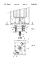
- FIG. 1 one of a hardware drilling machine coupled to quick change gear box
- FIG. 2 a top view along the section 2--2 in FIG. 1;
- FIG. 3 an explosion drawing of the hardware drilling machine and the quick change gear box
- FIG. 4 a top view along the section 4--4 in FIG. 3.
- FIG. 1 a machine frame stand (1) of a hardware drilling machine with a motor (2) is represented, on which a motor shaft (3) has a groove connection (4).
- a mounting plate (5) is provided on the machine frame stand (1).
- Two concentric elongated slots (12) are provided to take up the coupling bolts (6) in order to fasten the quick change gear box.
- a bore hole (13) On the end of the elongated slot which corresponds to the disengaged "uncoupled” state, a bore hole (13) has a large diameter for the bolt heads (11) of the coupling bolts (6) and, on the other end, which corresponds to the engaged "coupled” state, there is a small diameter for the bold body of the coupling bolts (6) which is illustrated in the sectional view along the Line 2--2 in FIG. 2.
- a bore hole (14) is located in the fastening block for the catch pin (7), which with the help of a spring (17) catches in the bore hole (14). This serves as a position transmitter and secures against the turning of the quick change gear box in relation to the mounting plate (5).
- the tool (9) in this case a milling cutter tool, is connected over a coupling (8) with the motor shaft (3)
- FIG. 3 shows an exploded view of the quick change gear box and the hardware drilling machine with a saw tooth coupling (15) and a centering member (16).
- FIG. 4 in which the sectional view along the Line 4--4 of FIG. 3 is shown, the fastening block (10) of the quick change gear box is turned in relation to the mounting plate (5).
- the bolt heads (11) of the coupling bolts (6) are now in a position in which they can be guided and inserted into the elongated slots (12) of the mounting plate (5).
- the concentric elongated slots (12)in the mounting plate (5) have, in this position, a bore hole (13) whose diameter corresponds to the bolt heads (11).
- the coupling bolts (6) thus, fully insert the bore holes (12)in order to fasten the quick change gear box to the hardware drilling machine, and then are pressed by a right turn of the fastening block (10) in the concentric slots (12).
- the diameter, of the elongated slots (12) in this position correspond to the diameter of the body of the coupling bolts (6) so that the bolt heads (11) lie on the elongated slot groove.
- the elongated slot grooves have an incline for the bolt heads (11).
- the coupling bolts (6) are pulled against the force of the springs (13) in the mounting plate (5).
- the catch pin (7) slides along the mounting plate (5) and is pressed in the engaged "coupled” position of FIG. 1 in the bore hole (14) by means of the spring (17). In this position the quick change gear box is engaged and secured against turning.
- the catch pin (7) In order to release the gear box, the catch pin (7) shall be pressed downwardly against the spring (17) and at the same time, the fastening block (10) shall be turned in a clock-wise direction.
- the bolt heads (11) are then located in the bore holes (13) of the elongated slots (12)--the diameter corresponding to the bolt heads (11)--and the quick change gear
Landscapes
- Engineering & Computer Science (AREA)
- Mechanical Engineering (AREA)
- Life Sciences & Earth Sciences (AREA)
- Wood Science & Technology (AREA)
- Forests & Forestry (AREA)
- Drilling Tools (AREA)
- Drilling And Boring (AREA)
- Earth Drilling (AREA)
- Gears, Cams (AREA)
Applications Claiming Priority (2)
| Application Number | Priority Date | Filing Date | Title |
|---|---|---|---|
| DE9309483U DE9309483U1 (de) | 1993-06-28 | 1993-06-28 | Schnellwechselgetriebe für Beschlagbohrmaschine |
| DE9309483U | 1993-06-28 |
Publications (1)
| Publication Number | Publication Date |
|---|---|
| US5439334A true US5439334A (en) | 1995-08-08 |
Family
ID=6894850
Family Applications (1)
| Application Number | Title | Priority Date | Filing Date |
|---|---|---|---|
| US08/266,946 Expired - Fee Related US5439334A (en) | 1993-06-28 | 1994-06-27 | Quick change gear box for hardware drilling machine |
Country Status (3)
| Country | Link |
|---|---|
| US (1) | US5439334A (it) |
| DE (1) | DE9309483U1 (it) |
| IT (1) | IT1269951B (it) |
Cited By (3)
| Publication number | Priority date | Publication date | Assignee | Title |
|---|---|---|---|---|
| CN106424842A (zh) * | 2016-11-18 | 2017-02-22 | 惠安灿锐信息技术咨询有限公司 | 一种基于物联网的智能多轴打孔设备 |
| CN109751365A (zh) * | 2019-02-12 | 2019-05-14 | 杭州景业智能科技有限公司 | 一种一拖四电机及齿轮箱快换装置 |
| US20210023668A1 (en) * | 2018-03-30 | 2021-01-28 | Makino Milling Machine Co., Ltd. | Spindle device of machine tool |
Families Citing this family (1)
| Publication number | Priority date | Publication date | Assignee | Title |
|---|---|---|---|---|
| IT1264750B1 (it) * | 1993-12-16 | 1996-10-04 | Elmepla S R L | Dispositivo automatico di connessione rapida di mandrini a teste operatrici di macchine formatrici di bicchieri di innesto assiale nei |
Citations (7)
| Publication number | Priority date | Publication date | Assignee | Title |
|---|---|---|---|---|
| US3757637A (en) * | 1970-09-15 | 1973-09-11 | E Eich | Device for the automatic replacement and adjustment of tool carriers, more particularly angular milling heads on the milling support of a machine tool |
| US3794436A (en) * | 1971-10-27 | 1974-02-26 | Rowlar Mfg Co | Machine tool having plural interchangeable transmissions |
| US4305189A (en) * | 1979-05-10 | 1981-12-15 | Miyakawa Industry Company, Limited | Attachment member for multiple-spindle head |
| US4614468A (en) * | 1983-12-15 | 1986-09-30 | Werkzeugmaschinenfabrik Adolf Waldrich Coburg Gmbh & Co. | Apparatus for facilitating the rotation of a tool-receiving device |
| US4650376A (en) * | 1984-12-06 | 1987-03-17 | Miyakawa Industry Co., Ltd. | Structure for installing a multispindle attachment on a drilling machine or the like |
| SU1366322A1 (ru) * | 1986-07-09 | 1988-01-15 | Горьковское Станкостроительное Производственное Объединение | Устройство дл креплени накладной головки |
| US4770575A (en) * | 1986-06-13 | 1988-09-13 | Gebruder Honsberg Gmbh | Centering and chucking system |
-
1993
- 1993-06-28 DE DE9309483U patent/DE9309483U1/de not_active Expired - Lifetime
-
1994
- 1994-06-27 IT ITMI941329A patent/IT1269951B/it active IP Right Grant
- 1994-06-27 US US08/266,946 patent/US5439334A/en not_active Expired - Fee Related
Patent Citations (7)
| Publication number | Priority date | Publication date | Assignee | Title |
|---|---|---|---|---|
| US3757637A (en) * | 1970-09-15 | 1973-09-11 | E Eich | Device for the automatic replacement and adjustment of tool carriers, more particularly angular milling heads on the milling support of a machine tool |
| US3794436A (en) * | 1971-10-27 | 1974-02-26 | Rowlar Mfg Co | Machine tool having plural interchangeable transmissions |
| US4305189A (en) * | 1979-05-10 | 1981-12-15 | Miyakawa Industry Company, Limited | Attachment member for multiple-spindle head |
| US4614468A (en) * | 1983-12-15 | 1986-09-30 | Werkzeugmaschinenfabrik Adolf Waldrich Coburg Gmbh & Co. | Apparatus for facilitating the rotation of a tool-receiving device |
| US4650376A (en) * | 1984-12-06 | 1987-03-17 | Miyakawa Industry Co., Ltd. | Structure for installing a multispindle attachment on a drilling machine or the like |
| US4770575A (en) * | 1986-06-13 | 1988-09-13 | Gebruder Honsberg Gmbh | Centering and chucking system |
| SU1366322A1 (ru) * | 1986-07-09 | 1988-01-15 | Горьковское Станкостроительное Производственное Объединение | Устройство дл креплени накладной головки |
Cited By (4)
| Publication number | Priority date | Publication date | Assignee | Title |
|---|---|---|---|---|
| CN106424842A (zh) * | 2016-11-18 | 2017-02-22 | 惠安灿锐信息技术咨询有限公司 | 一种基于物联网的智能多轴打孔设备 |
| US20210023668A1 (en) * | 2018-03-30 | 2021-01-28 | Makino Milling Machine Co., Ltd. | Spindle device of machine tool |
| CN109751365A (zh) * | 2019-02-12 | 2019-05-14 | 杭州景业智能科技有限公司 | 一种一拖四电机及齿轮箱快换装置 |
| CN109751365B (zh) * | 2019-02-12 | 2024-03-22 | 杭州景业智能科技股份有限公司 | 一种一拖四电机及齿轮箱快换装置 |
Also Published As
| Publication number | Publication date |
|---|---|
| DE9309483U1 (de) | 1993-09-02 |
| IT1269951B (it) | 1997-04-16 |
| ITMI941329A0 (it) | 1994-06-27 |
| ITMI941329A1 (it) | 1995-12-27 |
Similar Documents
| Publication | Publication Date | Title |
|---|---|---|
| US4842453A (en) | Guide apparatus for drilling oblique holes | |
| US4995768A (en) | Rapid change drill holder assembly | |
| US5442843A (en) | Drilling machine for drilling holes in furniture parts | |
| EP3436710B1 (en) | Improved device for joining parts of furniture and furnishing accessories | |
| US5657804A (en) | Mortise making device of a machining tool | |
| US6220796B1 (en) | Multipurpose drilling jig | |
| US4528874A (en) | Screw fasteners and drivers | |
| KR102173950B1 (ko) | 패널용 수직 수평 보링 장치 | |
| US4787432A (en) | Apparatus and method for producing mortise and tenon joints | |
| US5318082A (en) | Universal jointer | |
| US5439334A (en) | Quick change gear box for hardware drilling machine | |
| US7044462B2 (en) | Fixture | |
| DE59901103D1 (de) | Kraftgetriebener Schrauber | |
| US3041023A (en) | Separable mountings for electric motors or the like | |
| WO1987002923A1 (en) | Clamping device | |
| CN219466398U (zh) | 一种斜孔打孔机 | |
| US4146342A (en) | Fastener system | |
| EP2937016A1 (en) | Alignment device for joining together parts of furniture | |
| CN214350662U (zh) | 一种防晃动的翻转锁螺丝工装 | |
| CN212823808U (zh) | 一种三轴拧紧机径向等间距变位机构 | |
| US4031932A (en) | Planing attachment for jointers | |
| US3951273A (en) | Removable attachment for automating milling machines | |
| US5848863A (en) | Working machine having different working angle | |
| TWI678245B (zh) | 中空壁虎拉帽機 | |
| CN209228804U (zh) | 一种led显示屏箱体的四合一快锁 |
Legal Events
| Date | Code | Title | Description |
|---|---|---|---|
| AS | Assignment |
Owner name: GRASS AG, AUSTRIA Free format text: ASSIGNMENT OF ASSIGNORS INTEREST;ASSIGNOR:GRABHER, GUENTER;REEL/FRAME:007056/0556 Effective date: 19940608 |
|
| FPAY | Fee payment |
Year of fee payment: 4 |
|
| REMI | Maintenance fee reminder mailed | ||
| LAPS | Lapse for failure to pay maintenance fees | ||
| FP | Lapsed due to failure to pay maintenance fee |
Effective date: 20030808 |
|
| STCH | Information on status: patent discontinuation |
Free format text: PATENT EXPIRED DUE TO NONPAYMENT OF MAINTENANCE FEES UNDER 37 CFR 1.362 |