US5437761A - Lithium niobate crystal wafer, process for the preparation of the same, and method for the evaluation thereof - Google Patents
Lithium niobate crystal wafer, process for the preparation of the same, and method for the evaluation thereof Download PDFInfo
- Publication number
- US5437761A US5437761A US08/206,097 US20609794A US5437761A US 5437761 A US5437761 A US 5437761A US 20609794 A US20609794 A US 20609794A US 5437761 A US5437761 A US 5437761A
- Authority
- US
- United States
- Prior art keywords
- wafer
- lithium niobate
- crystal
- niobate crystal
- residual strain
- Prior art date
- Legal status (The legal status is an assumption and is not a legal conclusion. Google has not performed a legal analysis and makes no representation as to the accuracy of the status listed.)
- Expired - Fee Related
Links
Images


Classifications
-
- C—CHEMISTRY; METALLURGY
- C30—CRYSTAL GROWTH
- C30B—SINGLE-CRYSTAL GROWTH; UNIDIRECTIONAL SOLIDIFICATION OF EUTECTIC MATERIAL OR UNIDIRECTIONAL DEMIXING OF EUTECTOID MATERIAL; REFINING BY ZONE-MELTING OF MATERIAL; PRODUCTION OF A HOMOGENEOUS POLYCRYSTALLINE MATERIAL WITH DEFINED STRUCTURE; SINGLE CRYSTALS OR HOMOGENEOUS POLYCRYSTALLINE MATERIAL WITH DEFINED STRUCTURE; AFTER-TREATMENT OF SINGLE CRYSTALS OR A HOMOGENEOUS POLYCRYSTALLINE MATERIAL WITH DEFINED STRUCTURE; APPARATUS THEREFOR
- C30B33/00—After-treatment of single crystals or homogeneous polycrystalline material with defined structure
-
- C—CHEMISTRY; METALLURGY
- C30—CRYSTAL GROWTH
- C30B—SINGLE-CRYSTAL GROWTH; UNIDIRECTIONAL SOLIDIFICATION OF EUTECTIC MATERIAL OR UNIDIRECTIONAL DEMIXING OF EUTECTOID MATERIAL; REFINING BY ZONE-MELTING OF MATERIAL; PRODUCTION OF A HOMOGENEOUS POLYCRYSTALLINE MATERIAL WITH DEFINED STRUCTURE; SINGLE CRYSTALS OR HOMOGENEOUS POLYCRYSTALLINE MATERIAL WITH DEFINED STRUCTURE; AFTER-TREATMENT OF SINGLE CRYSTALS OR A HOMOGENEOUS POLYCRYSTALLINE MATERIAL WITH DEFINED STRUCTURE; APPARATUS THEREFOR
- C30B29/00—Single crystals or homogeneous polycrystalline material with defined structure characterised by the material or by their shape
- C30B29/10—Inorganic compounds or compositions
- C30B29/16—Oxides
- C30B29/22—Complex oxides
- C30B29/30—Niobates; Vanadates; Tantalates
Definitions
- the present invention relates to a lithium niobate crystal wafer which can be utilized as a substrate of an optical waveguide or elastic surface wave device, a process for the preparation of the same, and a method for the evaluation thereof. Particularly, it relates to a lithium niobate crystal wafer exhibiting remarkably reduced residual strain, a process for preparing the wafer at high productivity, and a method for evaluating the same.
- ferroelectric crystals such as lithium niobate and lithium tantalate crystals have been used for the production of elastic surface wave, Pockels, non-linear and pyroelectric elements and so on, by virtue of their excellent acoustic, electro-optical and pyroelectric effects.
- these crystals are grown by the Czocharalski method, annealed for the prevention of cracking in processing, poled for single polarization, and thereafter processed into a cylinder.
- This cylinder generally has a diameter of 50 to 130 mm and a length of 30 to 100 mm.
- the cylindrical crystal boule thus prepared is cut into blocks having a specific crystal orientation, or sliced into wafers, followed by lapping and polishing. Then, the resulting products are provided as crystals for various devices.
- the wafer When lithium niobate crystal is used in the form of a wafer, the wafer generally has a diameter of 50 to 125 mm and a thickness of 0.3 to 5 mm and is used in the production of optical waveguide, surface acoustic wave and pyroelectric elements and so on.
- the present invention has been made to solve these problems of the prior art and aims at providing a lithium niobate crystal wafer exhibiting reduced residual strain, a process for the preparation of the same, and a method for the evaluation thereof.
- the inventors of the present invention have made intensive studies for the above purpose with their attention directed to the absorption coefficient at a wavelength of 2.87 ⁇ m and, as the result of their studies, have found that when the absorption coefficients of a lithium niobate crystal wafer determined at that wavelength are uniform, the crystal wafer exhibits no or reduced residual strain and that the annealing of lithium niobate crystal in the form of a wafer is effective in uniforming the absorption coefficients to thereby reduce the residual strain, though the annealing a crystal in the form of a boule is ineffective in this respect. No study has been made on the relationship between the absorption coefficient and the residual strain.
- the lithium niobate crystal wafer of the present invention is characterized in that the deviations of the maximum and minimum absorption coefficients of the wafer at a wavelength of 2.87 ⁇ m from the average absorption coefficient thereof at that wavelength fall within the range of ⁇ 0.1 cm -1 exclusive of both borders. That is, the deviations thereof is necessary to fall within the range of from more than -0.1 cm -1 to less than +0.1 cm -1 .
- the absorption coefficient of lithium niobate crystal at a wavelength of 2.87 ⁇ m can be determined by measuring the spectral transmittance of the crystal and represents the concentration of hydride ions or protons contained in the crystal. Accordingly, the fact that non-uniform absorption coefficients at a wavelength of 2.87 ⁇ m are observed in a lithium niobate crystal wafer means that the proton concentration of the wafer is not homogeneous.
- Each absorption coefficient value was determined by the calculation according to the following formula based on the transmittances measured with a polarized light perpendicular to the z axis of the crystal: absorption coefficient ( ⁇ , cm -1 )
- T is the transmittance of absorption peak at a wavelength of 2.87 ⁇ m; To is the transmittance determined on the assumption that no absorption occurs; and t is the thickness (cm) of a sample crystal.
- the variation in the absorption coefficient at a wavelength of 2.87 ⁇ m in the wafer i.e., the deviations of the maximum and minimum absorption coefficients of the wafer surface from the average one thereof fall within the range of ⁇ 0.1 cm -1 exclusive of both borders, in order that the residual strains in a lithium niobate crystal wafer cannot be observed at all.
- the process for the preparation of a lithium niobate crystal wafer according to the present invention is characterized in that lithium niobate crystal is annealed in the form of a wafer, and thereafter the resulting wafer is lapped and polished.
- the lithium niobate crystal wafer of the present invention is prepared by growing lithium niobate crystal generally by the Czochralski method, subjecting the obtained crystal to annealing and poling, processing the crystal into a cylinder, slicing the cylindrical crystal boule into a wafer having a specific crystal orientation, annealing the wafer again, and subjecting the resulting wafer to lapping and polishing, and is used as a substrate of an optical waveguide or elastic surface wave device.
- Ordinary annealing conditions may be employed in the above annealing step.
- the annealing may be conducted at 1000° C. in an atomosphere of oxygen, nitrogen, argon, water vapor or a mixture of them under a reduced pressure for 10 hours.
- the annealing of lithium niobate crystal in the form of a wafer according to the present invention can afford a uniform proton concentration in the crystal in a short time in only one annealing run. This is conceivably because not only thermal diffusion of the protons in the crystal but also the migration thereof through the wafer surface contribute to the uniforming proton concentration owing to the thinness of the wafer.
- the proton concentration in lithium niobate crystal can be uniformed in a short time by annealing the crystal in the form of a wafer, which enables the preparation of a lithium niobate crystal wafer exhibiting reduced residual strain without fail at high productivity.
- the present invention it is essential for reduction in the residual strain of a lithium niobate crystal wafer that the variation in the absorption coefficient within the wafer fall within the range of ⁇ 0.1 cm -1 exclusive of both borders. Further, it is more effective in reducing the residual strain to further reduce the variation.
- a lithium niobate crystal wafer exhibiting reduced residual strain can be prepared at high productivity by annealing lithium niobate crystal in the form of a wafer and subjecting the resulting wafer to lapping and polishing.
- the method for the evaluation of a lithium niobate crystal wafer according to the present invention comprises determining the maximum and minimum absorption coefficients of the wafer at a wavelength of 2.87 ⁇ m.
- the lithium niobate crystal wafer of the present invention exhibits reduced residual strain, so that it is extremely suitable for use in optical waveguide and elastic surface wave devices as a substrate.
- the wafer when the crystal wafer exhibits both reduced residual strain and lowered proton concentration, the wafer is expected to solve the current DC drift problem of a light modulator or a photoswitch by virtue of its very low electric conductivity.
- a lithium niobate crystal wafer exhibiting sufficiently reduced residual strain can be prepared without fail at high productivity in a short time by annealing lithium niobate crystal in the form of a wafer. Further, the process of the present invention can be applied to any of the X to Z faces of a lithium niobate crystal wafer.
- the present invention remarkably facilitates the evaluation of a lithium niobate crystal wafer.
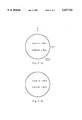
- FIGS. 1(a) and (b) show, respectively, the pattern of light absorption coefficient distribution and that of extinction ratio distribution on a crystal wafer (Z face) according to the prior art.
- FIGS. 2(a) and (b) show, respectively, the pattern of light absorption coefficient distribution and that of extinction ratio distribution on a crystal wafer (z face) according to the present invention.
- FIG. 3 is a schematic view of an optical system for measuring the extinction ratio distribution.
- each average absorption coefficient is the arithmetic mean of the absorption coefficients determined at twenty points selected in each wafer at uniform intervals, while each variation is the deviations of the maximum and minimum absorption coefficients among those determined at the twenty points from the average one.
- each wafer was examined for extinction ratio distribution on an X-Y table with a He-Ne laser (power output: 0.5 mW, beam diameter: 1 mm) as a light source and a Glan-Thompson polarizer.
- the extinction ratio was calculated by the following formula:
- Po is the optical power recorded when no sample is set; and P is that recorded when a sample is set.
- the strain of a lithium niobate crystal wafer has a directional property, because it is caused by the stress present in the crystal.
- a polarized light having a certain direction of polarization is made to strike on the wafer surface, so that the extinction ratio is high on the minus side in a case where the direction of the stress is parallel or perpendicular to the direction of polarization, while it approaches 0 in other cases.
- the residual strain of a lithium niobate crystal wafer is slight when the variation in the absorption coefficient in the wafer falls within the range of ⁇ 0.2 cm -1 .
- Particularly, scarcely any contour pattern of the extinction ratio is observed when the variation falls within the range of ⁇ 0.08 cm -1 .
- a lithium niobate crystal boule (Z-axis pulling, diameter: 80 mm, length: 50 mm) prepared by the Czochralski method was annealed, poled and sliced, followed by the lapping and polishing of both surfaces, giving thirty crystal wafers each having a thickness of 1.2 mm.
- the wafers were examined for absorption coefficient and residual strain in a similar manner to that of the Example 1.
- the average absorption coefficients of the wafers were different from each other and ranged from 2.5 to 3.0 cm -1 , and the variation in absorption coefficient in each wafer fell within the range of ⁇ 0.2 cm 31 1 or above. Further, each wafer was examined for extinction ratio distribution to give the residual strain distribution pattern as shown in FIG. 1(b).
- the above wafers were annealed at 1000° C. in the air for 2 hours and subjected again to lapping and polishing to give wafers each having a thickness of 1.0 mm. These wafers were examined for absorption coefficient and residual strain. The average absorption coefficient of each wafer was 1.5 cm -1 and the variation within each wafer fell within the range of ⁇ 0.08 cm -1 . Further, the wafers were each examined also for extinction ratio distribution to give uniform extinction ratios as shown in FIG. 2(b), which means that no residual strain is present in each wafer.
- a lithium niobate crystal boule (Z-axis pulling, diameter:80 mm, length: 50 mm) prepared by the Czochralski method was annealed, poled and sliced, followed by the lapping and polishing of both surfaces, giving thirty crystal wafers each having a thickness of 1.2 mm.
- the wafers were examined for absorption coefficient and residual strain in a similar manner to that of the Example 1.
- the average absorption coefficients of the wafers were different from each other and ranged from 2.3 to 2.6 cm -1 and the variation in absorption coefficient in each wafer fell within the range of ⁇ 0.2 cm -1 or above. Further, each wafer was examined for extinction ratio distribution to give a residual strain distribution pattern as shown in FIG. 1(b).
Landscapes
- Chemical & Material Sciences (AREA)
- Engineering & Computer Science (AREA)
- Crystallography & Structural Chemistry (AREA)
- Materials Engineering (AREA)
- Metallurgy (AREA)
- Organic Chemistry (AREA)
- Inorganic Chemistry (AREA)
- Crystals, And After-Treatments Of Crystals (AREA)
Applications Claiming Priority (2)
| Application Number | Priority Date | Filing Date | Title |
|---|---|---|---|
| JP5-072754 | 1993-03-09 | ||
| JP5072754A JPH06258539A (ja) | 1993-03-09 | 1993-03-09 | ニオブ酸リチウム結晶ウエハおよびその製造方法、並びに評価方法 |
Publications (1)
| Publication Number | Publication Date |
|---|---|
| US5437761A true US5437761A (en) | 1995-08-01 |
Family
ID=13498464
Family Applications (1)
| Application Number | Title | Priority Date | Filing Date |
|---|---|---|---|
| US08/206,097 Expired - Fee Related US5437761A (en) | 1993-03-09 | 1994-03-04 | Lithium niobate crystal wafer, process for the preparation of the same, and method for the evaluation thereof |
Country Status (3)
| Country | Link |
|---|---|
| US (1) | US5437761A (ja) |
| EP (1) | EP0615005A3 (ja) |
| JP (1) | JPH06258539A (ja) |
Cited By (5)
| Publication number | Priority date | Publication date | Assignee | Title |
|---|---|---|---|---|
| US5661997A (en) * | 1993-09-21 | 1997-09-02 | Johnson & Johnson Inc. | Method for evaluating the potential of sphagnum moss material for absorbing liquid |
| US5893982A (en) * | 1997-01-08 | 1999-04-13 | Seh America, Inc. | Prevention of edge stain in silicon wafers by oxygen annealing |
| US6255123B1 (en) * | 1998-11-17 | 2001-07-03 | Kenneth P. Reis | Methods of monitoring and maintaining concentrations of selected species in solutions during semiconductor processing |
| US7985294B2 (en) | 2005-03-04 | 2011-07-26 | Sumitomo Osaka Cement Co., Ltd. | Optical device and method of manufacturing the same |
| WO2014172131A3 (en) * | 2013-04-18 | 2015-12-10 | Drexel University | Methods of forming perovskite films |
Families Citing this family (2)
| Publication number | Priority date | Publication date | Assignee | Title |
|---|---|---|---|---|
| DE69819971T2 (de) * | 1997-07-25 | 2004-09-02 | Crystal Technology, Inc., Palo Alto | Vorbehandelte Kristalle aus Lithiumniobat und Lithiumtantalat und das Verfahren zu ihrer Herstellung |
| EP0921215A1 (en) * | 1997-12-05 | 1999-06-09 | Crystal Technology, Inc. | Electromagnetic radiation absorbant crystals of lithium niobate and lithium tantalate and methods of preparing the same |
Citations (6)
| Publication number | Priority date | Publication date | Assignee | Title |
|---|---|---|---|---|
| US3860467A (en) * | 1974-02-22 | 1975-01-14 | Western Electric Co | Method of etching a surface of a substrate comprising LITAO{HD 3 {B and chemically similar materials |
| US3954940A (en) * | 1974-11-04 | 1976-05-04 | Mcdonnell Douglas Corporation | Process for surface work strain relief of electrooptic crystals |
| US4390392A (en) * | 1980-09-16 | 1983-06-28 | Texas Instruments Incorporated | Method for removal of minute physical damage to silicon wafers by employing laser annealing |
| US4412886A (en) * | 1982-04-08 | 1983-11-01 | Shin-Etsu Chemical Co., Ltd. | Method for the preparation of a ferroelectric substrate plate |
| GB2119673A (en) * | 1982-05-04 | 1983-11-23 | Commissariat Energie Atomique | Process and apparatus for producing a strain free monocrystal of a crystalline ferroelectric compound |
| JPH03218996A (ja) * | 1990-01-25 | 1991-09-26 | Sumitomo Metal Mining Co Ltd | ニオブ酸リチウム単結晶の製造方法 |
-
1993
- 1993-03-09 JP JP5072754A patent/JPH06258539A/ja active Pending
-
1994
- 1994-03-04 US US08/206,097 patent/US5437761A/en not_active Expired - Fee Related
- 1994-03-08 EP EP19940301617 patent/EP0615005A3/en not_active Withdrawn
Patent Citations (6)
| Publication number | Priority date | Publication date | Assignee | Title |
|---|---|---|---|---|
| US3860467A (en) * | 1974-02-22 | 1975-01-14 | Western Electric Co | Method of etching a surface of a substrate comprising LITAO{HD 3 {B and chemically similar materials |
| US3954940A (en) * | 1974-11-04 | 1976-05-04 | Mcdonnell Douglas Corporation | Process for surface work strain relief of electrooptic crystals |
| US4390392A (en) * | 1980-09-16 | 1983-06-28 | Texas Instruments Incorporated | Method for removal of minute physical damage to silicon wafers by employing laser annealing |
| US4412886A (en) * | 1982-04-08 | 1983-11-01 | Shin-Etsu Chemical Co., Ltd. | Method for the preparation of a ferroelectric substrate plate |
| GB2119673A (en) * | 1982-05-04 | 1983-11-23 | Commissariat Energie Atomique | Process and apparatus for producing a strain free monocrystal of a crystalline ferroelectric compound |
| JPH03218996A (ja) * | 1990-01-25 | 1991-09-26 | Sumitomo Metal Mining Co Ltd | ニオブ酸リチウム単結晶の製造方法 |
Non-Patent Citations (4)
| Title |
|---|
| Journal of Applied Physics, vol. 68, No. 11, Dec. 1, 1990 New York pp. 5804 5809 Dhar et al Optical Properties of . . . p. 5404 US. * |
| Journal of Applied Physics, vol. 68, No. 11, Dec. 1, 1990 New York pp. 5804-5809 Dhar et al "Optical Properties of . . . " p. 5404 US. |
| Patent Abstracts of Japan, vol. 15, No. 500 (C 895) Dec. 18, 1991 & JP A 03 218 996 (Sumitomo Metal Mining Co., Ltd.) Sep. 26, 1991. * |
| Patent Abstracts of Japan, vol. 15, No. 500 (C-895) Dec. 18, 1991 & JP-A-03 218 996 (Sumitomo Metal Mining Co., Ltd.) Sep. 26, 1991. |
Cited By (5)
| Publication number | Priority date | Publication date | Assignee | Title |
|---|---|---|---|---|
| US5661997A (en) * | 1993-09-21 | 1997-09-02 | Johnson & Johnson Inc. | Method for evaluating the potential of sphagnum moss material for absorbing liquid |
| US5893982A (en) * | 1997-01-08 | 1999-04-13 | Seh America, Inc. | Prevention of edge stain in silicon wafers by oxygen annealing |
| US6255123B1 (en) * | 1998-11-17 | 2001-07-03 | Kenneth P. Reis | Methods of monitoring and maintaining concentrations of selected species in solutions during semiconductor processing |
| US7985294B2 (en) | 2005-03-04 | 2011-07-26 | Sumitomo Osaka Cement Co., Ltd. | Optical device and method of manufacturing the same |
| WO2014172131A3 (en) * | 2013-04-18 | 2015-12-10 | Drexel University | Methods of forming perovskite films |
Also Published As
| Publication number | Publication date |
|---|---|
| JPH06258539A (ja) | 1994-09-16 |
| EP0615005A3 (en) | 1994-11-23 |
| EP0615005A2 (en) | 1994-09-14 |
Similar Documents
| Publication | Publication Date | Title |
|---|---|---|
| Singh et al. | Nonlinear optical susceptibility of lithium formate monohydrate | |
| Matthews et al. | Properties of proton exchange waveguides in lithium tantalate | |
| US8189981B2 (en) | Stable lithium niobate waveguides, and methods of making and using same | |
| US6641662B2 (en) | Method for fabricating ultra thin single-crystal metal oxide wave retarder plates and waveguide polarization mode converter using the same | |
| Caird et al. | Measurements of losses and lasing efficiency in GSGG: Cr, Nd and YAG: Nd laser rods | |
| De Yoreo et al. | Sources of optical distortion in rapidly grown crystals of KH2PO4 | |
| EP0893515A1 (en) | Preconditioned crystals of lithium niobate and lithium tantalate and methods of preparing the same | |
| EP0615005A2 (en) | Lithium niobate crystal wafer, process for the preparation of the same, and method for the evaluation thereof | |
| Pracka et al. | Growth and characterization of LiNbO3 single crystals doped with Cu and Fe ions | |
| Lin et al. | Second order optical nonlinearities of radio frequency sputter‐deposited AlN thin films | |
| Wang et al. | Growth, properties and electrooptical applications of single crystal La3Ga5SiO14 | |
| RU2630123C2 (ru) | Кристаллическое тело, оптический прибор, имеющий кристаллическое тело, и способ изготовления кристаллического тела | |
| Nagata et al. | Reduced thermal decomposition of OH-free LiNbO3 substrates even in a dry gas atmosphere | |
| Savatinova et al. | Phase transition study of H: LiNbO3 waveguides by Raman spectroscopy | |
| Holman | The optical properties and processing of lithium niobate optical waveguides | |
| Korkishko et al. | Proton-exchanged waveguides in MgO-doped LiNbO 3: Optical and structural properties | |
| US5046801A (en) | Optical waveguide having low optical damage | |
| JP2985022B2 (ja) | 磁気光学素子及び光アイソレータ | |
| Tanaka et al. | Hydroxyl group formation caused by hydrogen diffusion into optical glass fibre | |
| Peuzin et al. | Optical waveguiding by very thin films of hydrogated amorphous silicon | |
| US6203728B1 (en) | Optical single crystal film process for producing the same and optical element comprising the same | |
| Hickernell | Low loss zinc oxide optical waveguides on amorphous substrates | |
| Singh et al. | The optical quality of mercurous halide crystals | |
| JP3040857B2 (ja) | 光アイソレータ | |
| JPH0886930A (ja) | ニオブ酸リチウム結晶ウエハ光導波路の形成方法 |
Legal Events
| Date | Code | Title | Description |
|---|---|---|---|
| AS | Assignment |
Owner name: NIHON KESSHO KOGAKU CO., LTD., JAPAN Free format text: ASSIGNMENT OF ASSIGNORS INTEREST;ASSIGNOR:KOIDE, AKIRA;REEL/FRAME:006907/0752 Effective date: 19940210 |
|
| FEPP | Fee payment procedure |
Free format text: PAYOR NUMBER ASSIGNED (ORIGINAL EVENT CODE: ASPN); ENTITY STATUS OF PATENT OWNER: LARGE ENTITY |
|
| REMI | Maintenance fee reminder mailed | ||
| LAPS | Lapse for failure to pay maintenance fees | ||
| FP | Lapsed due to failure to pay maintenance fee |
Effective date: 19990801 |
|
| STCH | Information on status: patent discontinuation |
Free format text: PATENT EXPIRED DUE TO NONPAYMENT OF MAINTENANCE FEES UNDER 37 CFR 1.362 |