US5422869A - Disc changer with common command element for turntable and disc carrier - Google Patents
Disc changer with common command element for turntable and disc carrier Download PDFInfo
- Publication number
- US5422869A US5422869A US07/949,653 US94965392A US5422869A US 5422869 A US5422869 A US 5422869A US 94965392 A US94965392 A US 94965392A US 5422869 A US5422869 A US 5422869A
- Authority
- US
- United States
- Prior art keywords
- disc
- carrier
- turntable
- rotation
- disc carrier
- Prior art date
- Legal status (The legal status is an assumption and is not a legal conclusion. Google has not performed a legal analysis and makes no representation as to the accuracy of the status listed.)
- Expired - Lifetime
Links
Images

Classifications
-
- G—PHYSICS
- G11—INFORMATION STORAGE
- G11B—INFORMATION STORAGE BASED ON RELATIVE MOVEMENT BETWEEN RECORD CARRIER AND TRANSDUCER
- G11B17/00—Guiding record carriers not specifically of filamentary or web form, or of supports therefor
- G11B17/02—Details
-
- G—PHYSICS
- G11—INFORMATION STORAGE
- G11B—INFORMATION STORAGE BASED ON RELATIVE MOVEMENT BETWEEN RECORD CARRIER AND TRANSDUCER
- G11B17/00—Guiding record carriers not specifically of filamentary or web form, or of supports therefor
- G11B17/22—Guiding record carriers not specifically of filamentary or web form, or of supports therefor from random access magazine of disc records
- G11B17/226—Guiding record carriers not specifically of filamentary or web form, or of supports therefor from random access magazine of disc records the magazine consisting of a single rotatable tray carrying the disks
Definitions
- the invention relates to a disc player comprising a stationary frame, a scanning device for scanning information discs, in particular optical or magneto-optical disc-shaped record carriers, disc carrier, and a driving mechanism.
- the scanning device comprises a turntable which is rotatable about a first axis of rotation and which has a supporting surface for supporting an information disc.
- the disc carrier is disc-shaped and is rotatable about an axis and has carrying surfaces for information discs.
- the mechanism comprises driving a command element which is rotatable about a second axis of rotation and has a first device for cooperation with a guide structure for guiding the turntable between a first position, in which the supporting surface of the turntable extends at one side of the plane defined by all the carrying surfaces of the disc carrier, and a second position, in which the supporting surface extends at the other side of the plane defined by all the carrying surfaces; and a second device for cooperation with the disc carrier to rotate the disc carrier between two well-defined (that is, accurately defined) disc-carrier positions.
- Such a disc player is known from GB-A 2,187,877 (herewith incorporated by reference).
- the known disc player has a housing with a drawer which is supported in a frame and can be slid into and out of the housing.
- the drawer has a disc carrier adapted to receive five optical discs.
- the drawer carries an electric motor for rotating the disc carrier and holding it in well-defined positions, microswitches being provided for the detection of these positions.
- the scanning device which comprises an optical scanning element and a turntable, is secured in an element which is movable relative to the frame.
- the drawer is slid in and out by means of an electric motor which is arranged in the housing and is coupled to a toothed command disc.
- the command disc has a toothed ring for cooperation with a toothed rack of the drawer and further has a spiral groove which is engaged by a pin of the slide carrying said element. After the drawer has been slid into the housing the command disc is rotated to bring the turntable from a rest position to a play position.
- a disc player of the type defined above requires a proper coordination between the rotary movements and positions of the disc carrier and the movements and positions of the turntable.
- a disadvantage of the known disc player is that for rotating the disc carrier and moving the turntable two separate drives are needed.
- the presence of two drives with associated electric motors and transmission mechanisms requires additional space, which is often scarce in modem compact equipment.
- dedicated electronic controls are needed for actuating one drive relative to the other drive at the correct instants in order to guarantee the appropriate positions of the disc carrier and the turntable relative to one another. Obtaining short access times is difficult as a result of the presence of two drives.
- the disc player in accordance with the invention is characterised in that the rotatable command element is a unitary element which comprises both the first device for cooperation with the guide structure for guiding the turntable and the second device for cooperation with the disc carrier that is, the command element surfaces forming the first device and second device are fixed with respect with each other, and move together as one element.
- the disc carrier and the turntable are coupled via the command element, so that only one drive motor is needed for the coordinated drive of the disc carrier and the turntable.
- An embodiment of the disc player in accordance with the invention is characterised in that the first device comprises a cam which is constantly in contact with a cam follower of the guide structure.
- This embodiment has the advantage that discontinuous movements of the turntable, and hence of the entire scanning device, are possible without lost motion.
- An embodiment of the disc player in accordance with the invention is characterised in that the cam is a polygonal cam which has circular-arc cam surfaces and is arranged eccentrically on the command element, the cam being retained between two upright edges of the cam follower.
- the movements of the turntable are coupled to the rotary movements of the disc carrier in a constructionally attractive manner.
- the cam arranged between the two upright edges of the cam follower guarantees a coupling free of lost motion and hence silent and accurate periodic movements and accurate positions of the scanning device.
- An embodiment of the disc player in accordance with the invention is characterised in that the second device comprises an eccentrically disposed journal on a pin which extends parallel to the second axis of rotation, the disc carrier having radially extending slots with which the journal engages by rotation of the command element in operation to rotate the disc carrier between said disc-carrier positions.
- the construction used in this embodiment is very suitable for the intermittent rotation of the disc carrier, the disc carrier being set into motion and stopped gradually, i.e. without impermissible acceleration and deceleration peaks.
- the construction produces minimal noise during operation, which is obviously important for an audio and/or video apparatus.
- the command element can be driven in two directions of rotation for the coordinated rotation and displacement of the disc carrier and the turntable. This has the advantage that during operation, regardless of the starting position of the disc carrier, it is always possible to select that direction of rotation which yields the shortest access time.
- An embodiment of the disc player in accordance with the invention in which the second device also cooperates with the disc carrier to latch the disc carrier in said disc-holder positions, is characterised in that the second device comprises a latching element arranged diametrically opposite the journal and the disc carrier is formed with radial ridges bounding the slots, the latching element being engageable between every two adjacent slots by rotation of the command element in operation to latch the disc carrier in said disc-carrier positions.
- the disc carrier is accurately yet simply held in the disc-carrier positions dictated by the construction.
- the number of slots is equal to the number of carrying surfaces, for example five slots for five carrying surfaces, and the latching element is constituted by an arcuate latching projection.
- An embodiment of the disc player in accordance with the invention in which the command element is disc-shaped and has two parallel side walls, is characterised in that the cam is arranged on one of the side walls and the journal and the latching element are arranged on the other side wall. In this way a compact construction in layers is possible for the disc player.
- An embodiment of the disc player in accordance with the invention is characterised in that the command element has a range of rotation in which the turntable is in a first position and engages a recess in one of the carrying surfaces of the stationary disc carrier, the supporting surface being spaced from the relevant carrying surface in a position suitable for supporting an information carrier.
- the scanning device In the stationary positions of the command element which occur in said range of rotation the scanning device is in the play position, an information disc present on the turntable being clear of the disc carrier and being rotated with the turntable during rotation of the turntable to allow scanning without mechanical contact.
- this embodiment is also characterised in that in operation as it performs a revolution the command element, starting from a stationary rotary position within said range of rotation, first moves the turntable from the first to the second position, then by rotating the disc carrier moves an adjacent carrying surface thereof above the turntable, and subsequently moves the turntable from the second to the first position while the disc carrier is stationary.
- the command element is utilised very efficiently and the turntable displacements are related to the disc-carrier rotations in a very reliable manner, the positions of the turntable and the disc carrier relative to one another during operation being well-defined at every instant.
- An embodiment of the disc player in accordance with the invention in which the disc player comprises a housing and the disc carrier is rotatably supported on a drawer which is movable between a slid-in position and a slid-out position, is characterised in that the scanning device and the driving mechanism with said command element are arranged on the drawer.
- This embodiment enables the disc carrier to be moved at least partly outside the housing while an information disc is being scanned. This makes it possible to exchange one or more discs without an interruption of the scanning process.
- An embodiment of the disc player in accordance with the invention in which the disc player comprises a drawer drive unit secured to the stationary frame, is characterised in that the drawer drive unit comprises a pivotable arm having one end which engages a groove formed in the drawer. This prevents the drawer from being subjected to abrupt accelerating forces, thereby guaranteeing smooth inward and outward movement of the drawer.
- the groove extends in a direction transverse to a direction of movement of the drawer.
- An embodiment of the disc player in accordance with the invention is characterised in that the driving mechanism can be energised both in the slid-in position and in the slid-out position of the drawer.
- This embodiment has the advantage that after an information disc has been exchanged it can be scanned already before the drawer is slid into the housing.
- this embodiment is provided with a "quick-play" button coupled to a microprocessor for an optimum use of the extremely short access time.
- An embodiment of the disc player in accordance with the invention in which the scanning device is secured to a supporting element which is movable along the first axis of rotation and which bears on inclined guide surfaces of a slide of said guide structure, which slide is movable transversely of the first axis of rotation, is characterised in that the slide is coupled to the first device of the command element.
- the slide is preferably movable in a direction oriented at an angle between 30 and 60 degrees relative to the normal to a front surface of the disc player.
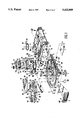
- FIG. 1 is an exploded view of the disc player in accordance with the invention
- FIG. 2 is an underneath view of a disc carrier of the disc player shown in FIG. 1,
- FIG. 3 is an underneath view of a command element
- FIG. 4 is a graph illustrating the relationship between the movements of three constructional elements of the disc player shown in FIG. 1.
- the disc player in accordance with the invention shown in FIG. 1 has a housing 1 comprising a front surface 1a formed with a slot 3 and a drawer 5 which can be slid into and out of the housing.
- the housing 1 accommodates a stationary frame 7 with guide elements 9 for guiding the drawer 5, which at opposite sides carries guide profiles 11 for cooperation with the guide elements 9.
- the drawer 5 is movable relative to the frame 7 in the directions indicated by the double arrow A, the drawer 5 being movable in a horizontal plane in the case that the disc player is installed in a horizontal position.
- the drawer 5 functions as a movable subframe carrying a scanning device 13 and a disc carrier 15.
- the scanning device 13 comprises a turntable 17 which is rotatable about an axis of rotation 17a and which has a supporting surface 17b for supporting and a centering mandrel 17c for centring an optically scannable disc such as a CD, a photo-CD or a CDI.
- the turntable 17 is secured on a drive shaft of an electric motor, not shown in the drawings.
- the scanning device 13 further comprises an objective unit which is radially movable relative to the turntable 17 and which has an objective 19 which is movable in a focusing direction F.
- the scanning device 19 is secured to a supporting member 21 by means of a plurality of elastic supporting elements 20, which supporting member comprises a plurality of, in the present case three, projections 23 which bear on an equal number of inclined guide surfaces 25 of a slide 27.
- the slide 27, which is arranged in a longitudinal opening 29 in the drawer 5, is horizontally movable to a limited extent in a direction indicated by the double arrow B, which in the present example is oriented at an angle of 36° relative to the arrow A.
- the slide 27 comprises guide strips 31 for cooperation with guide portions 33 of the drawer 5.
- the supporting member 21 When the slide 27 is moved in the direction indicated by the arrow B the supporting member 21, as a result of the cooperation between the projections 23 and the inclined guide surfaces 25 and the cooperation between the guide elements 24 and the guide grooves 26 of the supporting member 21, performs corresponding vertical movements as indicated by the double arrow C in order to move the turntable 17 along the axis of rotation 17a between a first position and a second position.
- the first position corresponds to the play position of the turntable, i.e. the position in which the supporting surface 17b can support an optical disc
- the second position corresponds to the position of the turntable in which this is not possible.
- the slide 27 has a guide surface 35 for cooperation with a guide pin 37 of a tilting element 39.
- the tilting element 39 forms part of a disc-pressure means which comprises a bracket 41 and a pressure member 43 which can be pressed against the turntable 17 by magnetic force.
- the bracket 41 is secured to the drawer 5 at three points 46, 47 and 48 i.e. at the location of the portions 46a, 47a and 48a.
- the tilting element 39 is pivotably mounted on the bracket 41.
- the pressure member 43 can be moved towards and away from the turntable by moving the slide 27 in the directions indicated by the arrow B.
- the disc carrier 15 which is disc-shaped, is rotatable about an axis of rotation 15a and has a plurality of, in the present example five substantially co-planar, carrying surfaces 51 with recesses 53 extending up to the circumference 16 of the disc carrier.
- the disc carrier 15 is supported by means of a cylindrical beating pin 55 arranged on the drawer 5 and engaging a corresponding central opening 57 in the disc carrier.
- the disc carrier 15 has five well-defined positions, hereinafter referred to as disc-carrier positions, in which always one of the carrying surfaces 51 is in a coaxial position relative to the turntable 17.
- the recesses 53 are dimensioned in such a way that in the disc-carrier positions the turntable 15 is movable through one of the recesses 53 between the first position (the play position), in which the supporting surface 17b is situated above one of the carrying surfaces 51, and the second position--the rest or pause position--, in which the supporting surface is situated at a lower level than the plane defined by all the carrying surfaces 51.
- the disc player in accordance with the invention further comprises a driving mechanism for rotating the disc carrier 15 between the different disc-carrier positions and for moving the turntable 17 between the first and the second position.
- the driving device comprises an electric motor 59, which drives a disc-shaped command element 63 via a transmission mechanism comprising inter alia a pinion 61, which pinion 61 is in mesh with a toothed ring 65 of the command element 63.
- the command element 63 which is rotatable about an axis of rotation 63a, is a unitary element which is journalled on a bearing pin 67 of the drawer 5.
- On a first side wall 69 (FIG.
- the command element 63 carries a polygonal cam 71 which is disposed eccentrically on the command element 63 and comprises a plurality of, in the present example three, circular-arc cam surfaces 71a, 71b and 71c.
- the command element 63 and the slide 27 are positioned in such a way relative to one another that the cam 71 extends between upright parallel edges or walls 73 and 75 of the slide 27 which form a cam follower.
- the distance between the two edges 73 and 75 is such that in any position the cam 71 is in contact with both edges, so that an accurate coupling without lost motion is obtained between the command element 63 and the slide 27.
- the slide 27 successively performs a movement in a direction as indicated by the arrow B and an oppositely directed movement, the movements being separated by a break.
- the command element 63 On a second side wall 77, which extends parallel to the first side wall, the command element 63 comprises an eccentrically disposed journal pin 79, which extends parallel to the axis of rotation 63a, and a latching collar 81 for cooperation with the disc carrier 15, which collar is situated diametrically opposite the journal pin 79.
- the disc carrier 15 has a plurality of, in the present example five, radial slots 85 and ribs or ridges 87 on one of its sides, in the present example the underside 83 (FIG. 2).
- the command element 63 and the disc carrier 15 are arranged in such a way relative to one another that the journal pin 79 engages one of the slots 85 during a part of the rotation of the command element 63, causing the disc carrier to be rotated through 72° from a given disc-carrier position to a new disc-carrier position, the latching collar 81 engaging between two ridges 87 during another part of the rotation in order to lock the disc carrier against rotation in the resulting disc-carrier position.
- This combination of pin and slot, and latching element form a Geneva mechanism.
- the disc carrier 15 and the turntable 17 are movably coupled to one another by means of the command element 63.
- the command element 63 has one range of rotational positions in which the disc carrier 15 is in one of the disc-carrier positions and the turntable 17 is in the play position and is situated in the recess 53 in one of the carrying surfaces 51.
- FIG. 4 illustrates the translation (x) of the turntable 17 (continuous line) and the rotation ( ⁇ ) of the disc carrier 15 (broken line) in one revolution ( ⁇ ) of the command element 63.
- the electric motor 59 is energised and first brings the turntable 17 and, consequently, the entire scanning device 13 from the first position x 1 to the second position x 2 , the disc carrier 15 being unlatched.
- the disc carrier 15 is rotated from a disc-carrier position ⁇ 1 until substantially a new disc-carrier position ⁇ 2 is reached, in which the command element occupies position ⁇ 3 .
- the disc carrier 15 is latched again and the turntable 17, and hence the entire scanning device 13, is moved from the second position x 2 to the first position x 1 .
- the command element is then in the rotational position ⁇ 4 .
- the turntable 17 remains in the play position x 1 and the disc carrier remains in the position ⁇ 2 .
- the disc player shown enables short access times of, for example, 1 to 2 seconds to be obtained.
- the disc player in accordance with the invention comprises a drawer drive unit which is secured to the stationary frame 7 and which comprises an electric motor 89, a transmission mechanism with inter alia a pinion 91, and a pivotable arm 93.
- the pivotable arm 93 is secured to a toothed wheel 95, which is rotatable about a pin 97 of the frame 7 and which meshes with the pinion 91.
- the pivotable arm 93 has a pin-shaped projection 99 which engages a groove 101 formed in the drawer 5, which groove extends in a direction transverse to the direction of movement A of the drawer 5.
- the arm 93 When the electric motor 89 is energised the arm 93 is pivoted about a pivotal axis 93a in order to provide a smooth movement of the drawer 5 as indicated by the arrow A.
- the electric motor 89 is started by actuating a button 103 at the front 1a of the housing 1.
- a switch 105 detects the end position, after which the electrode motor 89 is switched off.
- the drawer 5 is provided with two detector switches 105 and 107 (FIG. 1).
- the detector switch 107 serves for detecting a reference position of the disc carrier 15 and by means of a switching slide 108 it cooperates with a cam profile 111 (FIG. 2) of the disc carrier 15. This reference position is necessary for determining by means of a microprocessor how many revolutions of the command element 63 are needed to reach a desired disc-carrier position.
- the detector switch 109 can be actuated by an actuating projection 113 of the slide 27 and serves for switching off the electric motor 59 after the turntable 17 has reached the play position by rotation of the command element 63.
- the electric motor 59 and the process of scanning an information disc present on the turntable can be started by pressing control buttons at the front 1a of the housing 1.
- the disc player in accordance with the invention comprises a "quick-play" button 115 arranged on the drawer 5. By means of the button 115 the electric motor 59 can be started in the slid-out position of the drawer 5, which enables a particularly short access time to be obtained.
- the invention is not limited to the embodiment shown herein.
- some features of the invention can be used without the disc player having a drawer.
- the disc carrier may have more than or less than five carrying surfaces.
Landscapes
- Holding Or Fastening Of Disk On Rotational Shaft (AREA)
- Feeding And Guiding Record Carriers (AREA)
- Automatic Disk Changers (AREA)
Applications Claiming Priority (2)
| Application Number | Priority Date | Filing Date | Title |
|---|---|---|---|
| EP91203367 | 1991-12-20 | ||
| EP91203367 | 1991-12-20 |
Publications (1)
| Publication Number | Publication Date |
|---|---|
| US5422869A true US5422869A (en) | 1995-06-06 |
Family
ID=8208089
Family Applications (1)
| Application Number | Title | Priority Date | Filing Date |
|---|---|---|---|
| US07/949,653 Expired - Lifetime US5422869A (en) | 1991-12-20 | 1992-09-23 | Disc changer with common command element for turntable and disc carrier |
Country Status (6)
| Country | Link |
|---|---|
| US (1) | US5422869A (de) |
| EP (1) | EP0549033B1 (de) |
| JP (1) | JPH05242586A (de) |
| KR (1) | KR100246651B1 (de) |
| DE (1) | DE69220768T2 (de) |
| MY (1) | MY108251A (de) |
Cited By (11)
| Publication number | Priority date | Publication date | Assignee | Title |
|---|---|---|---|---|
| US5771213A (en) * | 1993-01-12 | 1998-06-23 | Matsushita Electric Industrial Co., Ltd. | Disc changer |
| US5852598A (en) * | 1995-12-19 | 1998-12-22 | Wiest; Peter P. | Disk-shaped sound recording medium, especially CD |
| US5867459A (en) * | 1995-04-28 | 1999-02-02 | U.S. Philips Corporation | Disc changer with rotatable disc support and disc player including the disc changer |
| US5872752A (en) * | 1995-09-26 | 1999-02-16 | Sony Corporation | Apparatus for recording and/or reproducing disk-like recording medium |
| US5892737A (en) * | 1996-12-31 | 1999-04-06 | Daewoo Electronics Co., Ltd. | Disk roulette control method and apparatus for use in an optical disk changer |
| US6151279A (en) * | 1996-07-31 | 2000-11-21 | Pioneer Electronic Corporation | Single motor disc player with a Geneva mechanism |
| US6219314B1 (en) * | 1998-06-22 | 2001-04-17 | U.S. Phillips Corporation | Disc changer with rotatable disc support and disc player including the disc changer |
| US6751169B1 (en) * | 1999-03-05 | 2004-06-15 | Koninklijke Philips Electronics N.V. | Disc changer comprising a rolling track |
| US20040223419A1 (en) * | 2003-05-09 | 2004-11-11 | Kazunari Ito | Carousel changer including a turntable having a plurality of trays |
| US20070263493A1 (en) * | 2006-03-27 | 2007-11-15 | Rodgers David T | Video game disc changer |
| US20130290989A1 (en) * | 2012-04-27 | 2013-10-31 | Hon Hai Precision Industry Co., Ltd. | Digital video disc player |
Citations (6)
| Publication number | Priority date | Publication date | Assignee | Title |
|---|---|---|---|---|
| US4670866A (en) * | 1984-08-10 | 1987-06-02 | Mitsubishi Denki Kabushiki Kaisha | Recording medium disk continuous-driving apparatus |
| GB2187877A (en) * | 1986-02-18 | 1987-09-16 | Sony Corp | Disc players |
| EP0386708A2 (de) * | 1989-03-07 | 1990-09-12 | Matsushita Electric Industrial Co., Ltd. | Plattenwechsler |
| US5146451A (en) * | 1989-12-30 | 1992-09-08 | Samsung Electronics Co., Ltd. | Compact disk player with two stacked, rotary, rotationally offset carrying plates for plural disks |
| US5173889A (en) * | 1990-04-25 | 1992-12-22 | Victor Company Of Japan, Ltd. | Multi-loaded disk drive arrangement |
| US5197056A (en) * | 1989-07-04 | 1993-03-23 | U.S. Philips Corporation | Disc record player |
Family Cites Families (1)
| Publication number | Priority date | Publication date | Assignee | Title |
|---|---|---|---|---|
| NL8901699A (nl) * | 1989-07-04 | 1991-02-01 | Philips Nv | Platenspeler. |
-
1992
- 1992-09-23 US US07/949,653 patent/US5422869A/en not_active Expired - Lifetime
- 1992-12-08 KR KR1019920023647A patent/KR100246651B1/ko not_active IP Right Cessation
- 1992-12-14 EP EP92203885A patent/EP0549033B1/de not_active Expired - Lifetime
- 1992-12-14 DE DE69220768T patent/DE69220768T2/de not_active Expired - Fee Related
- 1992-12-17 MY MYPI92002327A patent/MY108251A/en unknown
- 1992-12-21 JP JP4340574A patent/JPH05242586A/ja active Pending
Patent Citations (6)
| Publication number | Priority date | Publication date | Assignee | Title |
|---|---|---|---|---|
| US4670866A (en) * | 1984-08-10 | 1987-06-02 | Mitsubishi Denki Kabushiki Kaisha | Recording medium disk continuous-driving apparatus |
| GB2187877A (en) * | 1986-02-18 | 1987-09-16 | Sony Corp | Disc players |
| EP0386708A2 (de) * | 1989-03-07 | 1990-09-12 | Matsushita Electric Industrial Co., Ltd. | Plattenwechsler |
| US5197056A (en) * | 1989-07-04 | 1993-03-23 | U.S. Philips Corporation | Disc record player |
| US5146451A (en) * | 1989-12-30 | 1992-09-08 | Samsung Electronics Co., Ltd. | Compact disk player with two stacked, rotary, rotationally offset carrying plates for plural disks |
| US5173889A (en) * | 1990-04-25 | 1992-12-22 | Victor Company Of Japan, Ltd. | Multi-loaded disk drive arrangement |
Non-Patent Citations (2)
| Title |
|---|
| "Cams Design, Dynamics, and Accuracy", by Harold A. Rothbart, pp. 308-323, published 1956. |
| Cams Design, Dynamics, and Accuracy , by Harold A. Rothbart, pp. 308 323, published 1956. * |
Cited By (14)
| Publication number | Priority date | Publication date | Assignee | Title |
|---|---|---|---|---|
| US5771213A (en) * | 1993-01-12 | 1998-06-23 | Matsushita Electric Industrial Co., Ltd. | Disc changer |
| US5867459A (en) * | 1995-04-28 | 1999-02-02 | U.S. Philips Corporation | Disc changer with rotatable disc support and disc player including the disc changer |
| CN1122994C (zh) * | 1995-09-26 | 2003-10-01 | 索尼公司 | 记录和/或重放盘状记录介质的装置 |
| US5872752A (en) * | 1995-09-26 | 1999-02-16 | Sony Corporation | Apparatus for recording and/or reproducing disk-like recording medium |
| US5852598A (en) * | 1995-12-19 | 1998-12-22 | Wiest; Peter P. | Disk-shaped sound recording medium, especially CD |
| US6151279A (en) * | 1996-07-31 | 2000-11-21 | Pioneer Electronic Corporation | Single motor disc player with a Geneva mechanism |
| US5892737A (en) * | 1996-12-31 | 1999-04-06 | Daewoo Electronics Co., Ltd. | Disk roulette control method and apparatus for use in an optical disk changer |
| US6219314B1 (en) * | 1998-06-22 | 2001-04-17 | U.S. Phillips Corporation | Disc changer with rotatable disc support and disc player including the disc changer |
| US6751169B1 (en) * | 1999-03-05 | 2004-06-15 | Koninklijke Philips Electronics N.V. | Disc changer comprising a rolling track |
| US20040223419A1 (en) * | 2003-05-09 | 2004-11-11 | Kazunari Ito | Carousel changer including a turntable having a plurality of trays |
| US7333403B2 (en) * | 2003-05-09 | 2008-02-19 | Onkyo Corporation | Carousel changer including a turntable having a plurality of trays |
| US20070263493A1 (en) * | 2006-03-27 | 2007-11-15 | Rodgers David T | Video game disc changer |
| US20130290989A1 (en) * | 2012-04-27 | 2013-10-31 | Hon Hai Precision Industry Co., Ltd. | Digital video disc player |
| US8869178B2 (en) * | 2012-04-27 | 2014-10-21 | Fu Tai Hua Industry (Shenzhen) Co., Ltd. | Digital video disc player |
Also Published As
| Publication number | Publication date |
|---|---|
| EP0549033A1 (de) | 1993-06-30 |
| DE69220768D1 (de) | 1997-08-14 |
| JPH05242586A (ja) | 1993-09-21 |
| KR930014442A (ko) | 1993-07-23 |
| KR100246651B1 (ko) | 2000-03-15 |
| EP0549033B1 (de) | 1997-07-09 |
| MY108251A (en) | 1996-08-30 |
| DE69220768T2 (de) | 1998-02-05 |
Similar Documents
| Publication | Publication Date | Title |
|---|---|---|
| US5422869A (en) | Disc changer with common command element for turntable and disc carrier | |
| US4839881A (en) | Pickup transport device for optical disc apparatus | |
| EP0434133B1 (de) | Plattenspieler mit Detektionseinheit | |
| GB2172423A (en) | Power-operated device for assisting loading and unloading a disc player | |
| US5195078A (en) | Recording medium conveying device including a pair of circular coaxial gears | |
| US5197056A (en) | Disc record player | |
| US5084854A (en) | Optical disk reproducing apparatus | |
| US4152728A (en) | Releasable carriage drive unit for an optical disc player | |
| EP0389199A2 (de) | Automatisches Kassettenbandaufnahme- und -wiedergabegerät | |
| EP0330267B1 (de) | Ladevorrichtung sowie mit der Ladevorrichtung versehener Plattenspieler | |
| CA2075859C (en) | Laser disk player | |
| KR940001461B1 (ko) | 디스크 로딩기구를 갖는 디스크 레코드 플레이어 | |
| EP0434136B1 (de) | Plattenspieler sowie Zentriervorrichtung zum Gebrauch in dem Plattenspieler | |
| JP2006526867A (ja) | データキャリアディスクドライブを備えた機器及び該機器にデータキャリアを挿入する方法 | |
| KR0119449Y1 (ko) | 콤팩트디스크체인저의 데크플레이트 승강장치 | |
| EP1642291B1 (de) | Abnehmereinheit-homing-mechanismus für eine plattenlaufwerkeinheit | |
| JPH07334911A (ja) | ディスクプレイヤ | |
| WO1999023654A1 (en) | Cd changer with a driving mechanism operated by a single driving source | |
| KR100255843B1 (ko) | 회전형 씨디피 | |
| KR0141279B1 (ko) | 광디스크플레이어의 디스크로딩장치 | |
| KR20000034364A (ko) | 모터 구동방식 씨디 체인저의 록킹장치 | |
| JP2000076764A (ja) | ディスクローディング装置 | |
| JPS63288476A (ja) | 光ディスク装置 | |
| JPH02189722A (ja) | 光学式ディスク再生装置 | |
| KR20000011041U (ko) | 모터 구동방식 씨디 체인저 |
Legal Events
| Date | Code | Title | Description |
|---|---|---|---|
| AS | Assignment |
Owner name: U.S. PHILIPS CORP., NEW YORK Free format text: ASSIGNMENT OF ASSIGNORS INTEREST.;ASSIGNOR:VERSLEEGERS, JOZEF C.M.;REEL/FRAME:006263/0992 Effective date: 19920827 |
|
| STCF | Information on status: patent grant |
Free format text: PATENTED CASE |
|
| FPAY | Fee payment |
Year of fee payment: 4 |
|
| FPAY | Fee payment |
Year of fee payment: 8 |
|
| FPAY | Fee payment |
Year of fee payment: 12 |