US5409521A - Slag granulation - Google Patents
Slag granulation Download PDFInfo
- Publication number
- US5409521A US5409521A US08/199,309 US19930994A US5409521A US 5409521 A US5409521 A US 5409521A US 19930994 A US19930994 A US 19930994A US 5409521 A US5409521 A US 5409521A
- Authority
- US
- United States
- Prior art keywords
- trough
- enclosure
- atomiser
- granules
- granulator
- Prior art date
- Legal status (The legal status is an assumption and is not a legal conclusion. Google has not performed a legal analysis and makes no representation as to the accuracy of the status listed.)
- Expired - Fee Related
Links
- 239000002893 slag Substances 0.000 title claims description 21
- 238000005469 granulation Methods 0.000 title description 4
- 230000003179 granulation Effects 0.000 title description 4
- 239000008187 granular material Substances 0.000 claims abstract description 47
- 239000012768 molten material Substances 0.000 claims abstract description 20
- 239000012530 fluid Substances 0.000 claims abstract description 5
- 239000007789 gas Substances 0.000 claims description 20
- 239000003595 mist Substances 0.000 claims description 14
- XLYOFNOQVPJJNP-UHFFFAOYSA-N water Substances O XLYOFNOQVPJJNP-UHFFFAOYSA-N 0.000 claims description 14
- 238000000034 method Methods 0.000 claims description 12
- 238000001704 evaporation Methods 0.000 claims description 4
- 230000008020 evaporation Effects 0.000 claims description 4
- 239000000463 material Substances 0.000 claims description 4
- 239000000112 cooling gas Substances 0.000 claims description 3
- 239000007788 liquid Substances 0.000 claims description 3
- 239000007921 spray Substances 0.000 claims description 2
- XEEYBQQBJWHFJM-UHFFFAOYSA-N Iron Chemical compound [Fe] XEEYBQQBJWHFJM-UHFFFAOYSA-N 0.000 description 4
- 238000000605 extraction Methods 0.000 description 3
- 239000002245 particle Substances 0.000 description 3
- 239000006227 byproduct Substances 0.000 description 2
- 229910052742 iron Inorganic materials 0.000 description 2
- 238000004519 manufacturing process Methods 0.000 description 2
- 229910052751 metal Inorganic materials 0.000 description 2
- 239000002184 metal Substances 0.000 description 2
- 238000005096 rolling process Methods 0.000 description 2
- 239000011398 Portland cement Substances 0.000 description 1
- GWEVSGVZZGPLCZ-UHFFFAOYSA-N Titan oxide Chemical compound O=[Ti]=O GWEVSGVZZGPLCZ-UHFFFAOYSA-N 0.000 description 1
- 238000005054 agglomeration Methods 0.000 description 1
- 238000001816 cooling Methods 0.000 description 1
- 239000000110 cooling liquid Substances 0.000 description 1
- 238000009826 distribution Methods 0.000 description 1
- 229910044991 metal oxide Inorganic materials 0.000 description 1
- 150000004706 metal oxides Chemical class 0.000 description 1
- 150000002739 metals Chemical class 0.000 description 1
- 239000000203 mixture Substances 0.000 description 1
- 229910052755 nonmetal Inorganic materials 0.000 description 1
- 239000000047 product Substances 0.000 description 1
- 239000011819 refractory material Substances 0.000 description 1
- OGIDPMRJRNCKJF-UHFFFAOYSA-N titanium oxide Inorganic materials [Ti]=O OGIDPMRJRNCKJF-UHFFFAOYSA-N 0.000 description 1
Images

Classifications
-
- C—CHEMISTRY; METALLURGY
- C21—METALLURGY OF IRON
- C21B—MANUFACTURE OF IRON OR STEEL
- C21B3/00—General features in the manufacture of pig-iron
- C21B3/04—Recovery of by-products, e.g. slag
- C21B3/06—Treatment of liquid slag
- C21B3/08—Cooling slag
-
- B—PERFORMING OPERATIONS; TRANSPORTING
- B01—PHYSICAL OR CHEMICAL PROCESSES OR APPARATUS IN GENERAL
- B01J—CHEMICAL OR PHYSICAL PROCESSES, e.g. CATALYSIS OR COLLOID CHEMISTRY; THEIR RELEVANT APPARATUS
- B01J2/00—Processes or devices for granulating materials, e.g. fertilisers in general; Rendering particulate materials free flowing in general, e.g. making them hydrophobic
- B01J2/02—Processes or devices for granulating materials, e.g. fertilisers in general; Rendering particulate materials free flowing in general, e.g. making them hydrophobic by dividing the liquid material into drops, e.g. by spraying, and solidifying the drops
- B01J2/04—Processes or devices for granulating materials, e.g. fertilisers in general; Rendering particulate materials free flowing in general, e.g. making them hydrophobic by dividing the liquid material into drops, e.g. by spraying, and solidifying the drops in a gaseous medium
-
- C—CHEMISTRY; METALLURGY
- C21—METALLURGY OF IRON
- C21B—MANUFACTURE OF IRON OR STEEL
- C21B2400/00—Treatment of slags originating from iron or steel processes
- C21B2400/02—Physical or chemical treatment of slags
- C21B2400/022—Methods of cooling or quenching molten slag
- C21B2400/026—Methods of cooling or quenching molten slag using air, inert gases or removable conductive bodies
-
- C—CHEMISTRY; METALLURGY
- C21—METALLURGY OF IRON
- C21B—MANUFACTURE OF IRON OR STEEL
- C21B2400/00—Treatment of slags originating from iron or steel processes
- C21B2400/05—Apparatus features
- C21B2400/052—Apparatus features including rotating parts
-
- C—CHEMISTRY; METALLURGY
- C21—METALLURGY OF IRON
- C21B—MANUFACTURE OF IRON OR STEEL
- C21B2400/00—Treatment of slags originating from iron or steel processes
- C21B2400/05—Apparatus features
- C21B2400/052—Apparatus features including rotating parts
- C21B2400/054—Disc-shaped or conical parts for cooling, dispersing or atomising of molten slag rotating along vertical axis
-
- C—CHEMISTRY; METALLURGY
- C21—METALLURGY OF IRON
- C21B—MANUFACTURE OF IRON OR STEEL
- C21B2400/00—Treatment of slags originating from iron or steel processes
- C21B2400/05—Apparatus features
- C21B2400/066—Receptacle features where the slag is treated
- C21B2400/076—Fluidised bed for cooling
Definitions
- This invention relates to a method of, and apparatus for, granulating a molten material.
- the material may be a metal, such as iron; a metal oxide, such as titanium oxide; a non-metal, such as slag generated as a by-product of a metals production process; or a mixture thereof.
- the invention is particularly applicable to the granulation of slag tapped from an iron blast furnace.
- the granulated slag can be used as a Portland cement substitute in the manufacture of concrete.
- GB-B-2148330 discloses an apparatus and method for the granulation of slag.
- the granulator includes a rotary atomiser located within an enclosure.
- the base of the enclosure is in the form of a hopper containing a fluidised bed.
- a stream of molten slag is poured on to the atomiser which is rotated at a speed such that the slag is ejected from the atomiser as a sheet or ribbon.
- Air jets from nozzles surrounding the atomiser impinge upon the sheet or ribbon and break it up into granules and impart an upward motion to them.
- the granules then fall towards the base of the enclosure where they pass through a countercurrent stream of secondary air and then enter into the fluidised bed.
- This apparatus and method suffer from the disadvantage of the need to provide the air jets which impinge upon the sheet or ribbon to break it up into granular form.
- a considerable input energy requirement is necessary to provide air jets of sufficient force to break up the sheet or ribbon of slag and provide upward motion to the granules.
- this form of granulator is unreliable because it depends on the granules rolling down the inner wall of the enclosure to the exit point. If some granules stick to the wall, they prevent others from rolling down the wall and a build up of hardened granules on the wall soon occurs.
- An object of the present invention is to provide a method of, and apparatus for, granulating molten material in which the disadvantages of the prior art arrangements are overcome.
- a granulator comprises an enclosure; a rotary atomiser disposed within the enclosure; means for delivering molten material to the atomiser so that, in use, the material is broken into globules without the use of fluid jets and the globules are dispersed within the enclosure; an annular open-topped trough surrounding the atomiser to collect the granules formed from the at least partially frozen globules; and means for injecting gas into the trough to induce a circumferential movement of the granules in the trough towards at least one exit from the trough.
- the trough surrounding the atomiser collects and cools the granules, forming a mobile bed of granulate in the process.
- the circumferential motion of the bed is brought about by gas, normally air, which is injected at a small angle to the horizontal into the bed through a slotted plate or gas distributor.
- the granulate bed moves circumferentially around the trough to one or more exits from the trough.
- Granulation may start with no material in the trough, in which case a granulate bed is gradually built up, or a bed of cooled granulate from a previous run may be left in the trough to assist in the cooling process.
- the motion of the bed serves to encourage heat transfer between hot granulate and the injected gas and between hot and cold granulate.
- the bed motion acts to prevent re-agglomeration of the granules.
- the design of the slotted plate and trough allows relatively high gas velocities through the slots to promote the circumferential motion.
- the depth of the granulate bed is such that these high slot velocities are dissipated in the bed resulting in relatively low superficial gas velocities through the bed.
- the rotary atomiser conveniently comprises a thick disc of refractory material having a shaped top surface which promotes the desired slag droplet trajectory.
- the top surface may be dished to a greater or lesser extent depending upon desired trajectory, slag flow rate, cup speed range specification and desired particle size range.
- the device is rotated about a vertical axis by means of an electric motor which is located under appropriate covers beneath the device.
- the speed of rotation of the device is controlled as a function of slag flow rate, higher flows requiring higher rotational speeds to maintain droplet trajectory and size distribution. For this reason, the electric motor is driven by a variable speed drive (inverter).
- a stream of the molten material is delivered to a rotating atomiser disposed within an enclosure; the speed of rotation of the atomiser is such that the molten material is ejected from the atomiser in the form of globules without the use of fluid jets; the passage of the globules within the enclosure cause them to at least partially freeze to form granules; the granules are collected in an annular open-topped trough surrounding the atomiser; and gas is injected into the trough to induce a circumferential movement of the granules in the trough towards at least one exit from the trough.
- the globules of molten material ejected from the rotating atomiser fly outwardly towards the surrounding walls of the enclosure.
- the paths taken by the globules depend to a certain extent on the size of the globules.
- the globules spread out in the vertical plane as well as in the horizontal plane.
- the globules thus become in contact with the air in the enclosure and heat transfer between the globules and the air during the movement of the globules cause the globules to at least partially solidify to form granules.
- Some of the granules fall directly into the annular trough, while others will first impinge against the side wall of the enclosure before falling into the trough.
- the side wall of the enclosure to include a part which is at a higher level than the top of the trough, said higher part being of annular form with the lower end thereof leading to the top of the trough.
- This part of the side wall is conveniently liquid cooled such as by circulating liquid in a jacket mounted on the rear of the wall.
- the part of the side wall may have downwardly directed openings therein, and means are provided for directing cooling gas through the openings into the enclosure.
- the cooled wall or the air directed through the openings in the wall serve to prevent granules from sticking to the wall and the granules leave the wall and fall into the trough.
- an inclined surface extends downwardly from the rotary atomiser to the adjacent top edge of the trough.
- This surface conveniently has openings in it and gas is directed through the openings to the upper side of the surface. The gas and the inclined surface encourage the granules deposited on the surface to move into the trough.
- the means to control the exit gas temperature may comprise sprays or atomisers for introducing a water mist into the enclosure. The water mist serves to remove heat from the enclosure by evaporation and it reduces the temperature of the air in the enclosure.
- the water mist is totally evaporated and it does not wet any surface within the enclosure nor does it wet the granulated product.
- a simple control circuit is employed which compares the actual temperature in the enclosure with the predetermined desired temperature in the enclosure and adjusts the quantity of water mist applied to the enclosure accordingly. It must be emphasised that the water mist only serves to control the operating temperature and it does not assist in the break up of the molten material in the globules.
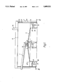
- FIG. 1 is a sectional elevation through apparatus in accordance with the invention
- FIG. 2 is a sectional elevation on the line II--II of FIG. 1;
- FIG. 3 is an inverted plan on the line III--III of FIG. 1.
- a granulator for granulating slag which is a by-product from a blast furnace consists of a rotary atomiser having a duct along which molten slag is passed and poured on to the atomiser, an annular trough surrounding the atomiser and an enclosure in which the atomiser and the trough are located.
- the rotary atomiser (1) comprises a stationary electric motor driven by, for example, a variable speed drive and having a vertical drive shaft.
- a flange (3) supporting a refractory dish or cup (4).
- the dish or cup has an upwardly facing concave surface and it is rotated about a vertical axis. The speed of rotation of the dish or cup can be varied.
- the atomiser is located within a generally cylindrical enclosure (6) and a feed duct (7) extends from outside the enclosure to a position above the atomiser (1).
- An outlet nozzle (8) permits molten slag flowing down the duct (7) to fall as a stream on to the concave surface of the cup (4).
- the atomiser (1) Surrounding the atomiser (1) there is an annular trough (10) and the top of the trough is at a lower level than the cup (4).
- a frusto-conical surface (11) extends downwardly from the rotary atomiser to the adjacent top edge of the trough.
- the part (6A) of the side wall which is at a higher level than the top of the trough, has its lower end leading to the top of the trough.
- the enclosure is covered by a top structure (12) through which extends at least one discharge pipe (14).
- the part (6A), of the side wall of the enclosure may have a water jacket mounted on the outside thereof with provision for cooling liquid to be circulated through the jacket in order to cool the wall.
- this part of the side wall has downwardly directed openings (15) therethrough and a hollow casing behind the wall enables a cooling gas, usually air, to be directed through the openings into the enclosure.
- the flow of air is downwardly towards the trough (10).
- the frusto-conical surface (11) has openings therethrough and a casing below the surface enables gas, usually air, to be directed through the openings to the upper side of the surface. The direction of the air flow through the openings is towards the trough (10).
- the base of the trough (10) comprises a wind box (20) which is supplied with air under pressure from a source (not shown).
- the air is expelled through slots (21) formed in the top of the box.
- the slots (21) are inclined at an angle of up to 25° to direct the air expelled from the air box in a single circumferential direction around the trough.
- extraction points (22) located at various positions around the circumference of the trough. In the arrangement shown, eight extraction points are provided.
- Each extraction point (22) consists either of a conduit (22') which extends through the wind box (20) into the bottom of the trough or a hatch (22") in a side wall of the trough.
- each conduit (22') or each duct (22") is positioned above one or other of a pair of conveyor belts or drag link conveyors (25) either directly or via inclined chutes (26).
- the conveyors may converge towards a single collection station (27).
- molten slag is allowed to flow down the duct (7) and fall as a stream on to the cup (4) of the atomiser (1) which is rotating at a speed usually between 750 rpm and 1200 rpm depending on slag flow rate. (Though speeds above this range are possible if required).
- the slag is ejected outwardly from the rotating cup (4) in the form of globules which, spread out into the enclosure and heat transfer takes place between each globule and air within the enclosure to at least solidify the outer skin of the globule so that it becomes a granule.
- the granules will leave the trough through the exit (22) but those that fail to leave through the exit will be moved on by the air flow from the wind box to the next exit (22) where an opportunity to exit from the trough occurs.
- the granules leaving the exits are deposited on the conveyors (25) and taken to the collection point (27). It is to be emphasised that the trough (10) contains a circumferentially mobile bed. The granules are moved around the trough by the air flow in the trough but, though relatively high air velocities are required to do this, air velocities in the bed are low, avoiding significant elutriation of smaller particles and maintaining a relatively dense bed.
- the hot air generated in the enclosure passes out of the enclosure through the or each discharge pipe (14) and it can be used to advantage elsewhere in the plant.
- at least one system comprising a pipe (32) having a plurality of nozzles (33) connected to it is supported within the enclosure, conveniently adjacent to the cup (4). Water is circulated through the pipe to issue through the nozzles in the form of a very fine mist.
- air operated atomisers may be employed to produce the mist.
- the mist injected into the enclosure is evaporated by the heat present in the enclosure and the mist does not wet any of the surfaces inside the enclosure, but the evaporation of the water does reduce the air temperature within the enclosure.
- control circuit (not shown) which detects the temperature of the air within the enclosure and compares it with a predetermined value. When the temperature of the air reaches the predetermined value, the mist is generated in the enclosure in order to reduce the temperature. In this way, the temperature should be reduced below the predetermined value.
Landscapes
- Chemical & Material Sciences (AREA)
- Engineering & Computer Science (AREA)
- Organic Chemistry (AREA)
- Manufacturing & Machinery (AREA)
- Materials Engineering (AREA)
- Metallurgy (AREA)
- Chemical Kinetics & Catalysis (AREA)
- Furnace Details (AREA)
- Glanulating (AREA)
- Manufacture Of Iron (AREA)
- Curing Cements, Concrete, And Artificial Stone (AREA)
- Medicines Containing Plant Substances (AREA)
- Cosmetics (AREA)
- Processing Of Solid Wastes (AREA)
- Silver Salt Photography Or Processing Solution Therefor (AREA)
- Dry Development In Electrophotography (AREA)
Applications Claiming Priority (3)
| Application Number | Priority Date | Filing Date | Title |
|---|---|---|---|
| GB9119788 | 1991-09-17 | ||
| GB919119788A GB9119788D0 (en) | 1991-09-17 | 1991-09-17 | Slag granulation |
| PCT/GB1992/001635 WO1993006250A1 (en) | 1991-09-17 | 1992-09-08 | Slag granulation |
Publications (1)
| Publication Number | Publication Date |
|---|---|
| US5409521A true US5409521A (en) | 1995-04-25 |
Family
ID=10701492
Family Applications (1)
| Application Number | Title | Priority Date | Filing Date |
|---|---|---|---|
| US08/199,309 Expired - Fee Related US5409521A (en) | 1991-09-17 | 1992-09-08 | Slag granulation |
Country Status (14)
| Country | Link |
|---|---|
| US (1) | US5409521A (cg-RX-API-DMAC7.html) |
| EP (1) | EP0605472B1 (cg-RX-API-DMAC7.html) |
| JP (1) | JPH06510820A (cg-RX-API-DMAC7.html) |
| KR (1) | KR100256864B1 (cg-RX-API-DMAC7.html) |
| AT (1) | ATE151116T1 (cg-RX-API-DMAC7.html) |
| AU (1) | AU653859B2 (cg-RX-API-DMAC7.html) |
| CA (1) | CA2116328C (cg-RX-API-DMAC7.html) |
| DE (1) | DE69218784T2 (cg-RX-API-DMAC7.html) |
| ES (1) | ES2101868T3 (cg-RX-API-DMAC7.html) |
| GB (1) | GB9119788D0 (cg-RX-API-DMAC7.html) |
| IN (1) | IN186482B (cg-RX-API-DMAC7.html) |
| TW (1) | TW206933B (cg-RX-API-DMAC7.html) |
| WO (1) | WO1993006250A1 (cg-RX-API-DMAC7.html) |
| ZA (1) | ZA927112B (cg-RX-API-DMAC7.html) |
Cited By (5)
| Publication number | Priority date | Publication date | Assignee | Title |
|---|---|---|---|---|
| US5735931A (en) * | 1993-08-12 | 1998-04-07 | Davy Mckee (Stockton) Limited | Slag granulation method and apparatus |
| US5810902A (en) * | 1994-10-26 | 1998-09-22 | Johns Manville International, Inc. | Method and apparatus for making air products |
| US6000242A (en) * | 1996-05-31 | 1999-12-14 | Kennecott Holdings Corporation | Apparatus for and process of water granulating matte or slag |
| US20110180945A1 (en) * | 2008-06-27 | 2011-07-28 | Commonwealth Scientific And Industrial Research Organisation | Granulation of molten material |
| US10801080B2 (en) * | 2016-03-11 | 2020-10-13 | Xi'an Jiaotong University | High-temperature liquid slag granulating system |
Families Citing this family (5)
| Publication number | Priority date | Publication date | Assignee | Title |
|---|---|---|---|---|
| KR100656769B1 (ko) * | 2006-06-28 | 2006-12-14 | (주)피엔알시스템 | 교량의 상부 구조물 내진성 강화 전단키 구조 |
| GB2493968B (en) * | 2011-08-26 | 2013-12-18 | Siemens Plc | Slag granulation device & method |
| GB2493969B (en) | 2011-08-26 | 2013-08-07 | Siemens Plc | Slag dispersal device and method |
| GB2505672B (en) * | 2012-09-06 | 2014-09-17 | Siemens Plc | Dry slag granulation system |
| CN114807463B (zh) * | 2022-05-26 | 2022-09-30 | 河北用邦环保设备科技有限公司 | 熔渣急冷粒化设备 |
Citations (6)
| Publication number | Priority date | Publication date | Assignee | Title |
|---|---|---|---|---|
| US3721511A (en) * | 1971-02-18 | 1973-03-20 | M Schlienger | Rotating arc furnace crucible |
| US4059372A (en) * | 1975-12-04 | 1977-11-22 | Ivan Andreevich Barannik | Plant for producing metallic pellets from salt-added magnesium or alloys thereof |
| US4256677A (en) * | 1976-04-12 | 1981-03-17 | Magnavox Government And Industrial Electronics Co. | Apparatus and method for making small spheres |
| US4373883A (en) * | 1979-01-09 | 1983-02-15 | Ishikawajima-Harima Jukogyo Kabushiki Kaisha | Apparatus for producing granules from molten metallurgical slags |
| US4909837A (en) * | 1988-03-09 | 1990-03-20 | Norddeutsche Affinerie Aktiengesellschaft | Process and apparatus for granulating molten slag |
| US5259861A (en) * | 1992-03-05 | 1993-11-09 | National Science Council | Method for producing rapidly-solidified flake-like metal powder |
-
1991
- 1991-09-17 GB GB919119788A patent/GB9119788D0/en active Pending
-
1992
- 1992-09-08 ES ES92919028T patent/ES2101868T3/es not_active Expired - Lifetime
- 1992-09-08 JP JP5505863A patent/JPH06510820A/ja active Pending
- 1992-09-08 EP EP92919028A patent/EP0605472B1/en not_active Expired - Lifetime
- 1992-09-08 KR KR1019940700861A patent/KR100256864B1/ko not_active Expired - Lifetime
- 1992-09-08 CA CA002116328A patent/CA2116328C/en not_active Expired - Fee Related
- 1992-09-08 WO PCT/GB1992/001635 patent/WO1993006250A1/en not_active Ceased
- 1992-09-08 US US08/199,309 patent/US5409521A/en not_active Expired - Fee Related
- 1992-09-08 DE DE69218784T patent/DE69218784T2/de not_active Expired - Fee Related
- 1992-09-08 AU AU25071/92A patent/AU653859B2/en not_active Ceased
- 1992-09-08 AT AT92919028T patent/ATE151116T1/de active
- 1992-09-14 IN IN818DE1992 patent/IN186482B/en unknown
- 1992-09-16 TW TW081107300A patent/TW206933B/zh active
- 1992-09-17 ZA ZA927112A patent/ZA927112B/xx unknown
Patent Citations (6)
| Publication number | Priority date | Publication date | Assignee | Title |
|---|---|---|---|---|
| US3721511A (en) * | 1971-02-18 | 1973-03-20 | M Schlienger | Rotating arc furnace crucible |
| US4059372A (en) * | 1975-12-04 | 1977-11-22 | Ivan Andreevich Barannik | Plant for producing metallic pellets from salt-added magnesium or alloys thereof |
| US4256677A (en) * | 1976-04-12 | 1981-03-17 | Magnavox Government And Industrial Electronics Co. | Apparatus and method for making small spheres |
| US4373883A (en) * | 1979-01-09 | 1983-02-15 | Ishikawajima-Harima Jukogyo Kabushiki Kaisha | Apparatus for producing granules from molten metallurgical slags |
| US4909837A (en) * | 1988-03-09 | 1990-03-20 | Norddeutsche Affinerie Aktiengesellschaft | Process and apparatus for granulating molten slag |
| US5259861A (en) * | 1992-03-05 | 1993-11-09 | National Science Council | Method for producing rapidly-solidified flake-like metal powder |
Cited By (7)
| Publication number | Priority date | Publication date | Assignee | Title |
|---|---|---|---|---|
| US5735931A (en) * | 1993-08-12 | 1998-04-07 | Davy Mckee (Stockton) Limited | Slag granulation method and apparatus |
| US5810902A (en) * | 1994-10-26 | 1998-09-22 | Johns Manville International, Inc. | Method and apparatus for making air products |
| US5882372A (en) * | 1994-10-26 | 1999-03-16 | Johns Manville International, Inc. | Apparatus for use in confining a gaseous stream containing wet or sticky particles or fibers |
| US6000242A (en) * | 1996-05-31 | 1999-12-14 | Kennecott Holdings Corporation | Apparatus for and process of water granulating matte or slag |
| US20110180945A1 (en) * | 2008-06-27 | 2011-07-28 | Commonwealth Scientific And Industrial Research Organisation | Granulation of molten material |
| US9409235B2 (en) * | 2008-06-27 | 2016-08-09 | Commonwealth Scientific And Industrial Research Organisation | Granulation of molten material |
| US10801080B2 (en) * | 2016-03-11 | 2020-10-13 | Xi'an Jiaotong University | High-temperature liquid slag granulating system |
Also Published As
| Publication number | Publication date |
|---|---|
| EP0605472B1 (en) | 1997-04-02 |
| JPH06510820A (ja) | 1994-12-01 |
| ES2101868T3 (es) | 1997-07-16 |
| EP0605472A1 (en) | 1994-07-13 |
| CA2116328C (en) | 1999-11-16 |
| DE69218784T2 (de) | 1997-07-10 |
| WO1993006250A1 (en) | 1993-04-01 |
| TW206933B (cg-RX-API-DMAC7.html) | 1993-06-01 |
| ZA927112B (en) | 1993-04-22 |
| GB9119788D0 (en) | 1991-10-30 |
| ATE151116T1 (de) | 1997-04-15 |
| AU2507192A (en) | 1993-04-27 |
| CA2116328A1 (en) | 1993-04-01 |
| DE69218784D1 (de) | 1997-05-07 |
| AU653859B2 (en) | 1994-10-13 |
| KR940702556A (ko) | 1994-08-20 |
| KR100256864B1 (ko) | 2000-05-15 |
| IN186482B (cg-RX-API-DMAC7.html) | 2001-09-15 |
Similar Documents
| Publication | Publication Date | Title |
|---|---|---|
| US5735931A (en) | Slag granulation method and apparatus | |
| EP2300139B1 (en) | Method for atomising molten slag | |
| US5409521A (en) | Slag granulation | |
| US5435945A (en) | Method and apparatus for generating sulphur seed particles for sulphur granule production | |
| KR101695171B1 (ko) | 슬래그 과립화 시스템 및 작동 방법 | |
| JP2014208344A (ja) | 溶融材料の造粒機 | |
| US3054139A (en) | Method and apparatus for pelleting molten slag | |
| SE412712B (sv) | Forfarande och anleggning for framstellning av pulver genom granulering av smelta | |
| US4373883A (en) | Apparatus for producing granules from molten metallurgical slags | |
| JP2639572B2 (ja) | 粒状スラグの製造装置 | |
| CN110090595B (zh) | 一种斜面冷却造粒系统 | |
| RU2388709C1 (ru) | Установка для переработки шлакового расплава и способ переработки шлакового расплава в этой установке | |
| SU1527203A1 (ru) | Способ утилизации тепла шлаков и устройство дл его осуществлени | |
| SU1284699A1 (ru) | Установка дл получени дроби | |
| US4231227A (en) | Prill tower rake | |
| JPH0733872Y2 (ja) | 造粒装置 | |
| SU1186640A1 (ru) | Гранул тор-воздухопрогреватель | |
| SU725804A1 (ru) | Устройство дл центробежной гранул ции расплава | |
| JPS6330060B2 (cg-RX-API-DMAC7.html) | ||
| JPS5919531A (ja) | 溶融物の粒化方法 |
Legal Events
| Date | Code | Title | Description |
|---|---|---|---|
| AS | Assignment |
Owner name: ASHMORE HOUSE, ENGLAND Free format text: ASSIGNMENT OF ASSIGNORS INTEREST;ASSIGNORS:FEATHERSTONE, WILLIAM BARRY;MACAULEY, DEREK;REEL/FRAME:006988/0927 Effective date: 19940211 |
|
| FPAY | Fee payment |
Year of fee payment: 4 |
|
| REMI | Maintenance fee reminder mailed | ||
| LAPS | Lapse for failure to pay maintenance fees | ||
| LAPS | Lapse for failure to pay maintenance fees |
Free format text: PATENT EXPIRED FOR FAILURE TO PAY MAINTENANCE FEES (ORIGINAL EVENT CODE: EXP.); ENTITY STATUS OF PATENT OWNER: LARGE ENTITY |
|
| STCH | Information on status: patent discontinuation |
Free format text: PATENT EXPIRED DUE TO NONPAYMENT OF MAINTENANCE FEES UNDER 37 CFR 1.362 |
|
| FP | Lapsed due to failure to pay maintenance fee |
Effective date: 20030425 |