US5364247A - Sealing structure for scroll type compressor - Google Patents
Sealing structure for scroll type compressor Download PDFInfo
- Publication number
- US5364247A US5364247A US08/063,438 US6343893A US5364247A US 5364247 A US5364247 A US 5364247A US 6343893 A US6343893 A US 6343893A US 5364247 A US5364247 A US 5364247A
- Authority
- US
- United States
- Prior art keywords
- orbiting
- fixed
- initiating
- scroll
- discharge port
- Prior art date
- Legal status (The legal status is an assumption and is not a legal conclusion. Google has not performed a legal analysis and makes no representation as to the accuracy of the status listed.)
- Expired - Fee Related
Links
Images


Classifications
-
- F—MECHANICAL ENGINEERING; LIGHTING; HEATING; WEAPONS; BLASTING
- F04—POSITIVE - DISPLACEMENT MACHINES FOR LIQUIDS; PUMPS FOR LIQUIDS OR ELASTIC FLUIDS
- F04C—ROTARY-PISTON, OR OSCILLATING-PISTON, POSITIVE-DISPLACEMENT MACHINES FOR LIQUIDS; ROTARY-PISTON, OR OSCILLATING-PISTON, POSITIVE-DISPLACEMENT PUMPS
- F04C27/00—Sealing arrangements in rotary-piston pumps specially adapted for elastic fluids
- F04C27/005—Axial sealings for working fluid
-
- F—MECHANICAL ENGINEERING; LIGHTING; HEATING; WEAPONS; BLASTING
- F04—POSITIVE - DISPLACEMENT MACHINES FOR LIQUIDS; PUMPS FOR LIQUIDS OR ELASTIC FLUIDS
- F04C—ROTARY-PISTON, OR OSCILLATING-PISTON, POSITIVE-DISPLACEMENT MACHINES FOR LIQUIDS; ROTARY-PISTON, OR OSCILLATING-PISTON, POSITIVE-DISPLACEMENT PUMPS
- F04C18/00—Rotary-piston pumps specially adapted for elastic fluids
- F04C18/02—Rotary-piston pumps specially adapted for elastic fluids of arcuate-engagement type, i.e. with circular translatory movement of co-operating members, each member having the same number of teeth or tooth-equivalents
- F04C18/0207—Rotary-piston pumps specially adapted for elastic fluids of arcuate-engagement type, i.e. with circular translatory movement of co-operating members, each member having the same number of teeth or tooth-equivalents both members having co-operating elements in spiral form
- F04C18/0246—Details concerning the involute wraps or their base, e.g. geometry
- F04C18/0269—Details concerning the involute wraps
Definitions
- the present invention relates to a scroll type compressor provided with a fixed scroll and an orbiting scroll, which compresses a gas, as the volume of a compression chamber defined between both scrolls decreases. More particularly, it relates to a sealing structure.
- a compression chamber converges to a gap defined between initiating sections of spiral elements of the orbiting and fixed scrolls according to the movement of the orbiting scroll.
- a refrigerant gas in the compression chamber is discharged through a discharge port which is bored in a base plate of the fixed scroll.
- Japanese Unexamined Patent Publication No. 59-58187 discloses a scroll type compressor.
- This compressor has initiating sections of spiral elements having generally larger thicknesses than those of the remaining sections thereof.
- involute curves are utilized to form both outer and inner spiral walls from initiating points to terminating points thereof, respectively.
- a part of the inner spiral wall of the initiating section of the spiral element includes a straight portion. As the straight portion is formed, the thickness of the initiating section of the spiral element is enlarged compared to that of a compressor employing involute curves. The enlargement of the thickness increases the pressure withstanding ability of the initiating sections of the spiral elements.
- Japanese Unexamined Patent Publication No. 57-148088 and Japanese Unexamined Utility Model Publication No. 60-128995 disclose structures which increase the sealing ability of the slidable contacting portions between the base plates of the scrolls and the end surfaces of the spiral elements thereof.
- Each one of the compressors disclosed in the above-mentioned publications includes sealing members interposed between the respective base plates and the end surfaces of the spiral elements.
- the discharge resistance influences the discharge pulsation and the operational efficiency of the compressor.
- discharge pulsation occurs, noise is generated.
- the compressor disclosed in Japanese Unexamined Patent Publication No. 57-148088 includes notched grooves communicating to a discharge port, which are formed in the initiating section of the spiral element of the fixed scroll, in order to increase the radius of the discharge port.
- the discharge port should not overlap with the successive compression chamber, when the discharge process is completed. Therefore, the radius of the discharge port will be restricted.
- the radius of the discharge port can be increased. This can be achieved by enlarging the area of the initiating section of the spiral element of the orbiting scroll which covers the discharge port.
- the disposed locations of the sealing members will be influenced.
- the initiating section of the sealing member greatly influences the prevention of leakage of the high pressured gas in the compression chamber which communicates to the discharge port. Therefore, the initiating section of the sealing member is desirably placed as close as possible to the initiating section of the spiral element.
- the sealing member integrally movable with the orbiting scroll will be extended over the discharge port to overlap therewith. This overlapping may cause the initiating section of the sealing member to be damaged due to the discharged high pressure gas from the discharge port. Therefore, the initiating section of the sealing member at the orbiting scroll cannot be extended to the vicinity of the initiating section of the fixed spiral element beyond the relative position of the discharge port.
- the primary object of the present invention is to provide a sealing structure for a scroll type compressor, which achieves high pressure withstanding ability, high sealing performance and low discharge resistance of the initiating section of the spiral element.
- the scroll type compressor according to the present invention includes a fixed scroll having a fixed spiral element and a fixed end plate.
- An orbiting scroll includes an orbiting spiral element and an orbiting end plate, and is revolvable in opposition to oppose to the fixed scroll.
- a plurality of compression chambers are defined between the fixed and orbiting scrolls, and volumes thereof are decreased in response to the revolution of the orbiting scroll.
- a discharge port opens to one of the compression chambers.
- the thicknesses of the initiating sections of the fixed and orbiting spiral elements are larger than those of remaining sections thereof, respectively.
- Spiral sealing members are interposed between the fixed and orbiting end plates and the associated orbiting and fixed spiral elements, and are in slidable contact with the orbiting and fixed end plates, respectively. At least one of the sealing members is movable with the orbiting spiral element, and a cross-section area of an initiating section of the sealing member is larger than that of the remaining section thereof.
- the pressure withstanding ability of the initiating section of the spiral element is increased. Further, the area of the initiating section of the spiral element for covering the discharge port can be increased, and the width of the initiating section of the sealing member can be widened, Therefore, the strength of the initiating section of the sealing member can be improved.
- the radius of the discharge port is to be increased, damage thereto can be prevented, even though the sealing member extends over the discharge port.
- the initiating position of the sealing member can be as close as possible to the initiating section of the spiral element of the orbiting scroll.
- the discharge resistance can be reduced due to increasing the radius of the discharge port.
- FIG. 1 is a cross sectional view showing an embodiment of a compressor according to the present invention
- FIG. 2 is an enlarged fragmentary cross sectional view taken along line 2--2 in FIG. 1;
- FIG. 3 is an enlarged cross sectional view showing the essential portion of the compressor when the discharge process is completed
- FIG. 4 is an enlarged cross sectional view showing the essential portion of the compressor when the initiating section of the sealing member disposed at the orbiting scroll side is protected over the discharge port;
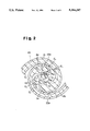
- FIG. 5 is an enlarged cross sectional view showing the essential portion of a compressor according to another embodiment.
- a front housing 2 is secured to a fixed scroll 1 which has a combined function as a rear housing.
- a ring-shaped base plate 3 is secured at the inner peripheral surface of the fixed scroll 1, which contacts with the end surface of the front housing 2.
- a rotary shaft 4 is rotatably supported within the front housing 2.
- An eccentric pin 5 is integrally formed with the rotary shaft 4. The eccentric pin 5 protrudes into the peripheral wall of the fixed scroll 1 through a central bore formed at the base plate 3.
- a balance weight 6 and a bushing 7 are rotatably supported by the eccentric pin 5.
- a revolvable orbiting scroll 8 is supported by the bushing 7 so as to oppose and slidably engage with the fixed scroll 1.
- Compression chambers P and P0 are defined between fixed and orbiting end plates 1a and 8a, and fixed and orbiting spiral elements 1b and 8b of both scrolls 1 and 8, respectively.
- a fixed ring 9 is fixed to the inner surface of the base plate so as to oppose orbiting scroll 8.
- a plurality of regulating holes 9a each having a circular shape are equiangularly formed in the fixed ring 9 so as to regulate the revolution of the orbiting scroll 8.
- An orbiting ring 10 is fixed to a back surface of the orbiting end plate 8a.
- a plurality of regulating holes 10a each having a circular shape are equiangularly formed in the orbiting ring 10.
- Disc shaped shoes 11A and 11B each having a smaller radius than those of the regulating holes 9a and 10a are fitted into the regulating holes 9a and 10a, respectively.
- a ball 12 is inserted into the space defined between the opposing shoes 11A and 11B.
- Both shoes 11A and 11B, and the ball 12 are clamped between the base plate 3 and the orbiting scroll 8 due to the reaction in the compression stage where the gas is compressed by both scrolls. Hence, they become an integral part.
- a circular revolvable area of the shoes 11A and 11B is defined within the regulating holes 9a and 10a.
- the diameter of the revolvable area of the shoes 11A and 11B is designed to be equal to the orbiting radius of the eccentric pin 5. Therefore, the orbiting scroll 8 will revolve without rotating itself, while shoes 11A and 11B are nipped between the respective circumferences of the regulating holes 9a and 10a and move along the circumferences of the regulating holes 9a and 10a in response to the revolution of the eccentric pin 5.
- Refrigerant gas guided through an inlet 1c formed in the outer peripheral wall of the fixed scroll 1 flows into the compression chambers P defined between both scrolls 1 and 8. Volumes of the compression chambers are decreased in response to the revolution of the orbiting scroll 8, so as to converge to the gap defined between initiating sections 1e and 8c of the fixed and orbiting spiral elements 1b and 8b of the scrolls 1 and 8, respectively.
- the gas compressed according to the decrease of the volumes of the compression chambers P and P0 is discharged into a discharge chamber 13 through a discharge port 1d formed in the fixed end plate 1a.
- the discharge chamber 13 is normally closed by means of a discharge valve 14 disposed at the discharge chamber 13 side.
- Sealing members 15 and 16 formed of synthetic resin are fitted into the distal surfaces of the fixed and orbiting spiral elements 1b and 8b, respectively.
- the sealing member 15 contacts the orbiting end plate 8a of the orbiting scroll 8.
- the seal member 16 contacts the fixed end plate 1a of the fixed scroll 1. Both sealing members 15 and 16 are in slidable contact with the orbiting and fixed end plates 8a and 1a, respectively, in response to the orbiting movement of the orbiting scroll 8.
- the initiating sections 1e and 8c of the fixed and orbiting spiral elements 1b and 8b are formed thicker than any other remaining portions thereof, so as to increase the pressure withstanding ability.
- An inner wall of the initiating section 8c is formed along a first circular arc R12, a second circular arc R11 and a straight line L1.
- An inner wall of the initiating section 1c is formed along a first circular arc R22, a second circular arc R21 and a straight line L2.
- the circular arcs R11 and R21 have the same radius and length.
- the circular arcs R12 and R22 have the same radius and length.
- the straight line L1 is a common tangent line to the circular arcs R11 and R12.
- the straight line L2 is a common tangent line to the circular arcs R21 and R22.
- involute curves E1 and E2 Major portions of the inner and outer walls of the fixed and orbiting spiral elements 1b and 8b except the initiating sections 1e and 8c are formed along involute curves E1 and E2.
- the involute curves E1 and E2 originate from a basic circle C0.
- the second circular arcs R11 and R21 are smoothly connected to the involute curves E1.
- the first circular arcs R12 and R22 are smoothly connected to the involute curves E2.
- a connecting point P1 connecting the circular arc R11 or R21 with the involute curve E1 corresponds to the distal point of the involute line having an arbitrary involute angle ⁇ .
- a connecting point P2 connecting the circular arc R12 or R22 with the involute curve E2 corresponds to the distal point of the involute line having an involute angle ( ⁇ +180°) which is advanced from the involute angle ⁇ by 180°.
- the walls along the straight lines L1 and L2 will slidably contact each other at the predetermined orbital points with respect to the orbiting scroll 8, according to the shape of the walls, as shown in FIG. 3.
- Initiating sections 15a and 16a of the spiral sealing members 15 and 16 extend closely to the initiating sections of the fixed and orbiting spiral elements 1b and 8b, respectively.
- the initiating sections 15a and 16a are broader than the remaining sections thereof, so as to match the shapes of the initiating sections 1e and 8c of the fixed and orbiting spiral elements 1b and 8b, respectively.
- the initiating section 16a of the sealing member 16 is capable of covering a major part of the discharge port 1d.
- the width of the initiating section 16a of the sealing member 16 is conformed with the thickness of the initiating section 8c of the orbiting spiral element 8b. Accordingly, the durability of the initiating section 16a is significantly greater than those of the remaining sections of the sealing member 16. Therefore, the projection end 16b of the sealing member 16 extending over the discharge port 1d will not be damaged even when the highly pressurized refrigerant gas is applied thereon.
- the tip of the initiating section of the sealing member 16 can be placed as closely as possible to the initiating section of the orbiting spiral element 8b, so as to improve the sealing ability of the compression chamber P0.
- the walls are formed along the straight line L2 in such a way that the thickness of the initiating section 8c increases in comparison with the case where the walls are formed along the internal involute curves E2. Therefore, the area where the initiating section 8c of the orbiting scroll 8 covers the discharge port 1d can be significantly increased. As a result, the cross sectional area of the discharge port 1d can be enlarged, and the discharge resistance can be reduced.
- the proportion of the projection end 16b of the sealing member 16 extending over the discharge port 1d is increased.
- it can be expressed by taking a ratio of K2/K1, where K1 is a length of the straight line between intersecting points Q1 and Q2 of the circumferential edge of the discharge port 1d with the circumferential edge of the sealing member 16, and K2 is a magnitude which the sealing member 16 extends over the discharge port 1d.
- the present invention includes that the thickness of the initiating section of the spiral element is larger than that of the remaining section thereof, and at .least the cross sectional area of the initiating section of the sealing member which is integrally movable with the orbiting scroll is larger than that of the remaining area thereof. Therefore, the high pressure withstanding ability, high sealing ability and low discharge resistance of the initiating section of the spiral element can be achieved.
- the shapes of the initiating sections 15a and 16a of the sealing members 15 and 16, respectively can be altered to either a circular or an elliptical shape.
- the thickness of the initiating section can be altered to be larger than those of the remaining sections thereof.
- the initiating section of the spiral element is not to be limited to being formed along a circular arc or a straight line. If suitable for forming the compression chambers, other curves can be employed.
Landscapes
- Engineering & Computer Science (AREA)
- Mechanical Engineering (AREA)
- General Engineering & Computer Science (AREA)
- Rotary Pumps (AREA)
Applications Claiming Priority (2)
| Application Number | Priority Date | Filing Date | Title |
|---|---|---|---|
| JP4-129111 | 1992-05-21 | ||
| JP12911192A JPH05321855A (ja) | 1992-05-21 | 1992-05-21 | スクロール型圧縮機におけるシール構造 |
Publications (1)
| Publication Number | Publication Date |
|---|---|
| US5364247A true US5364247A (en) | 1994-11-15 |
Family
ID=15001343
Family Applications (1)
| Application Number | Title | Priority Date | Filing Date |
|---|---|---|---|
| US08/063,438 Expired - Fee Related US5364247A (en) | 1992-05-21 | 1993-05-18 | Sealing structure for scroll type compressor |
Country Status (4)
| Country | Link |
|---|---|
| US (1) | US5364247A (ko) |
| JP (1) | JPH05321855A (ko) |
| KR (1) | KR970003263B1 (ko) |
| DE (1) | DE4316770A1 (ko) |
Cited By (13)
| Publication number | Priority date | Publication date | Assignee | Title |
|---|---|---|---|---|
| US5580228A (en) * | 1993-12-27 | 1996-12-03 | Nippondenso Co., Ltd. | Scroll compressor having grooves for seal members |
| US5584677A (en) * | 1994-03-15 | 1996-12-17 | Nippondenso Co., Ltd. | Scroll compressor having a bevelled facing section |
| US5636976A (en) * | 1994-11-16 | 1997-06-10 | Daido Metal Company Ltd. | Tip seal for scroll type compressor and manufacturing method therefor |
| WO1998016745A1 (en) * | 1996-10-17 | 1998-04-23 | Scroll Technologies | Scroll element having a relieved thrust surface |
| US6045136A (en) * | 1997-06-16 | 2000-04-04 | Garlock Inc. | Split sealing element |
| US6074185A (en) * | 1998-11-27 | 2000-06-13 | General Motors Corporation | Scroll compressor with improved tip seal |
| US6126422A (en) * | 1997-10-24 | 2000-10-03 | American Standard Inc. | Tip seal for scroll type compressor and manufacturing method therefor |
| CN1309959C (zh) * | 2002-08-28 | 2007-04-11 | Lg电子株式会社 | 涡旋式压缩机的排量改变装置 |
| US20120230855A1 (en) * | 2011-03-09 | 2012-09-13 | Seong Sanghun | Scroll compressor |
| WO2018084868A1 (en) * | 2016-11-07 | 2018-05-11 | Wood Mark W | Scroll compressor with circular surface terminations |
| US11022118B2 (en) | 2016-04-27 | 2021-06-01 | Mark W. Wood | Concentric vane compressor |
| US11480178B2 (en) | 2016-04-27 | 2022-10-25 | Mark W. Wood | Multistage compressor system with intercooler |
| US11686309B2 (en) | 2016-11-07 | 2023-06-27 | Mark W. Wood | Scroll compressor with circular surface terminations |
Families Citing this family (1)
| Publication number | Priority date | Publication date | Assignee | Title |
|---|---|---|---|---|
| JP4711659B2 (ja) * | 2004-10-27 | 2011-06-29 | Ntn株式会社 | スクロール型圧縮機用チップシール |
Citations (6)
| Publication number | Priority date | Publication date | Assignee | Title |
|---|---|---|---|---|
| JPS57148088A (en) * | 1981-03-09 | 1982-09-13 | Sanden Corp | Scroll type fluid machinery |
| JPS5958187A (ja) * | 1982-09-26 | 1984-04-03 | Sanden Corp | スクロ−ル型圧縮機 |
| JPS60128995A (ja) * | 1983-12-16 | 1985-07-10 | Hitachi Ltd | 水中ポンプ |
| JPS62223488A (ja) * | 1986-03-22 | 1987-10-01 | Toyota Autom Loom Works Ltd | スクロ−ル型コンプレツサ−のシ−ル部材 |
| JPS62276289A (ja) * | 1986-05-23 | 1987-12-01 | Mitsubishi Heavy Ind Ltd | スクロ−ル流体機械 |
| US5217358A (en) * | 1991-02-19 | 1993-06-08 | Kabushiki Kaisha Toyoda Jidoshokki Seisakusho | Scroll type compressor with elongated discharging part |
Family Cites Families (1)
| Publication number | Priority date | Publication date | Assignee | Title |
|---|---|---|---|---|
| JPS60142899U (ja) * | 1984-03-02 | 1985-09-21 | 横河電機株式会社 | 確認付記憶回路 |
-
1992
- 1992-05-21 JP JP12911192A patent/JPH05321855A/ja active Pending
-
1993
- 1993-05-18 US US08/063,438 patent/US5364247A/en not_active Expired - Fee Related
- 1993-05-19 DE DE19934316770 patent/DE4316770A1/de not_active Withdrawn
- 1993-05-21 KR KR1019930008735A patent/KR970003263B1/ko not_active IP Right Cessation
Patent Citations (7)
| Publication number | Priority date | Publication date | Assignee | Title |
|---|---|---|---|---|
| JPS57148088A (en) * | 1981-03-09 | 1982-09-13 | Sanden Corp | Scroll type fluid machinery |
| JPS5958187A (ja) * | 1982-09-26 | 1984-04-03 | Sanden Corp | スクロ−ル型圧縮機 |
| EP0105684A1 (en) * | 1982-09-26 | 1984-04-18 | Sanden Corporation | Scroll type refrigerant compressor with improved spiral element |
| JPS60128995A (ja) * | 1983-12-16 | 1985-07-10 | Hitachi Ltd | 水中ポンプ |
| JPS62223488A (ja) * | 1986-03-22 | 1987-10-01 | Toyota Autom Loom Works Ltd | スクロ−ル型コンプレツサ−のシ−ル部材 |
| JPS62276289A (ja) * | 1986-05-23 | 1987-12-01 | Mitsubishi Heavy Ind Ltd | スクロ−ル流体機械 |
| US5217358A (en) * | 1991-02-19 | 1993-06-08 | Kabushiki Kaisha Toyoda Jidoshokki Seisakusho | Scroll type compressor with elongated discharging part |
Non-Patent Citations (2)
| Title |
|---|
| Abstract of Japanese Patent Publication No. & JP 62 223488 A, published Oct. 1, 1987. * |
| Abstract of Japanese Patent Publication No. 62-223488, published Oct. 1, 1987. |
Cited By (20)
| Publication number | Priority date | Publication date | Assignee | Title |
|---|---|---|---|---|
| US5580228A (en) * | 1993-12-27 | 1996-12-03 | Nippondenso Co., Ltd. | Scroll compressor having grooves for seal members |
| US6074141A (en) * | 1993-12-27 | 2000-06-13 | Nippondenso Co., Ltd. | Scroll compressor having grooves for seal members |
| US5584677A (en) * | 1994-03-15 | 1996-12-17 | Nippondenso Co., Ltd. | Scroll compressor having a bevelled facing section |
| US5636976A (en) * | 1994-11-16 | 1997-06-10 | Daido Metal Company Ltd. | Tip seal for scroll type compressor and manufacturing method therefor |
| WO1998016745A1 (en) * | 1996-10-17 | 1998-04-23 | Scroll Technologies | Scroll element having a relieved thrust surface |
| US5791887A (en) * | 1996-10-17 | 1998-08-11 | Scroll Technologies | Scroll element having a relieved thrust surface |
| US6045136A (en) * | 1997-06-16 | 2000-04-04 | Garlock Inc. | Split sealing element |
| US6126422A (en) * | 1997-10-24 | 2000-10-03 | American Standard Inc. | Tip seal for scroll type compressor and manufacturing method therefor |
| US6270713B1 (en) * | 1997-10-24 | 2001-08-07 | American Standard International Inc. | Tip seal for scroll type compressors and manufacturing method therefor |
| US6074185A (en) * | 1998-11-27 | 2000-06-13 | General Motors Corporation | Scroll compressor with improved tip seal |
| CN1309959C (zh) * | 2002-08-28 | 2007-04-11 | Lg电子株式会社 | 涡旋式压缩机的排量改变装置 |
| US20120230855A1 (en) * | 2011-03-09 | 2012-09-13 | Seong Sanghun | Scroll compressor |
| US8308460B2 (en) * | 2011-03-09 | 2012-11-13 | Lg Electronics Inc. | Scroll compressor |
| USRE46106E1 (en) * | 2011-03-09 | 2016-08-16 | Lg Electronics Inc. | Scroll compressor |
| US11022118B2 (en) | 2016-04-27 | 2021-06-01 | Mark W. Wood | Concentric vane compressor |
| US11480178B2 (en) | 2016-04-27 | 2022-10-25 | Mark W. Wood | Multistage compressor system with intercooler |
| WO2018084868A1 (en) * | 2016-11-07 | 2018-05-11 | Wood Mark W | Scroll compressor with circular surface terminations |
| US11339786B2 (en) | 2016-11-07 | 2022-05-24 | Mark W. Wood | Scroll compressor with circular surface terminations |
| US11686309B2 (en) | 2016-11-07 | 2023-06-27 | Mark W. Wood | Scroll compressor with circular surface terminations |
| US20240044334A1 (en) * | 2016-11-07 | 2024-02-08 | Mark W. Wood | Scroll compressor with circular surface terminations |
Also Published As
| Publication number | Publication date |
|---|---|
| KR970003263B1 (ko) | 1997-03-15 |
| JPH05321855A (ja) | 1993-12-07 |
| DE4316770A1 (de) | 1993-11-25 |
| KR930023601A (ko) | 1993-12-21 |
Similar Documents
| Publication | Publication Date | Title |
|---|---|---|
| US5364247A (en) | Sealing structure for scroll type compressor | |
| EP0009355B1 (en) | Scroll-type fluid compressor units | |
| US6139287A (en) | Scroll type fluid machine | |
| US4304535A (en) | Scroll-type compressor units with minimum housing and scroll plate radii | |
| US9157438B2 (en) | Scroll compressor with bypass hole | |
| EP0648932B1 (en) | Scroll type compressor | |
| JPH08247053A (ja) | スクロール圧縮機 | |
| US5427513A (en) | Scroll type compressor having a displaced discharge port | |
| EP0318189B1 (en) | Scroll machine | |
| US5249943A (en) | Scroll type compressor having recessed buffer means in a spiral wrap flat face | |
| KR0161996B1 (ko) | 스크롤형 압축기 | |
| KR101119720B1 (ko) | 스크롤 압축기 | |
| JP2005273453A (ja) | スクロール圧縮機 | |
| US5242283A (en) | Scroll type compressor with elongated discharge port | |
| US6368087B2 (en) | Scroll-type fluid displacement apparatus having spiral start portion with thick base and thin tip | |
| KR100458799B1 (ko) | 스러스트면을가진스크롤엘레멘트 | |
| KR102454720B1 (ko) | 스크롤 압축기 | |
| US6478556B2 (en) | Asymmetric scroll compressor | |
| US4927341A (en) | Scroll machine with relieved flank surface | |
| US5217358A (en) | Scroll type compressor with elongated discharging part | |
| JP3882343B2 (ja) | スクロール型圧縮機 | |
| JP2884883B2 (ja) | スクロール型圧縮機における冷媒ガス吐出構造 | |
| US6336798B1 (en) | Rotation preventing mechanism for scroll-type fluid displacement apparatus | |
| KR100195166B1 (ko) | 스크롤 압축기 | |
| JPH10205468A (ja) | スクロール型コンプレッサ |
Legal Events
| Date | Code | Title | Description |
|---|---|---|---|
| AS | Assignment |
Owner name: KABUSHIKI KAISHA TOYODA JIDOSHOKKI SEISAKUSHO, JAP Free format text: ASSIGNMENT OF ASSIGNORS INTEREST;ASSIGNORS:FUKANUMA, TETSUHIKO;KOBAYASHI, HISAO;YOSHIDA, TETSUO;AND OTHERS;REEL/FRAME:006674/0011 Effective date: 19930520 |
|
| CC | Certificate of correction | ||
| FEPP | Fee payment procedure |
Free format text: PAYOR NUMBER ASSIGNED (ORIGINAL EVENT CODE: ASPN); ENTITY STATUS OF PATENT OWNER: LARGE ENTITY |
|
| FPAY | Fee payment |
Year of fee payment: 4 |
|
| REMI | Maintenance fee reminder mailed | ||
| LAPS | Lapse for failure to pay maintenance fees | ||
| STCH | Information on status: patent discontinuation |
Free format text: PATENT EXPIRED DUE TO NONPAYMENT OF MAINTENANCE FEES UNDER 37 CFR 1.362 |
|
| FP | Lapsed due to failure to pay maintenance fee |
Effective date: 20021115 |