US536274A - Watch case-pendant - Google Patents
Watch case-pendant Download PDFInfo
- Publication number
- US536274A US536274A US536274DA US536274A US 536274 A US536274 A US 536274A US 536274D A US536274D A US 536274DA US 536274 A US536274 A US 536274A
- Authority
- US
- United States
- Prior art keywords
- pendant
- bow
- stem
- watch
- washer
- Prior art date
- Legal status (The legal status is an assumption and is not a legal conclusion. Google has not performed a legal analysis and makes no representation as to the accuracy of the status listed.)
- Expired - Lifetime
Links
- 238000010276 construction Methods 0.000 description 6
- 241001125292 Balaena mysticetus Species 0.000 description 5
- 239000002184 metal Substances 0.000 description 2
- 230000000284 resting effect Effects 0.000 description 2
- 238000005392 polarisation enhancment during attached nucleus testing Methods 0.000 description 1
Images
Classifications
-
- G—PHYSICS
- G04—HOROLOGY
- G04B—MECHANICALLY-DRIVEN CLOCKS OR WATCHES; MECHANICAL PARTS OF CLOCKS OR WATCHES IN GENERAL; TIME PIECES USING THE POSITION OF THE SUN, MOON OR STARS
- G04B3/00—Normal winding of clockworks by hand or mechanically; Winding up several mainsprings or driving weights simultaneously
- G04B3/04—Rigidly-mounted keys, knobs or crowns
Definitions
- This invention relates to certain improvements in watches, and moreparticularly to pendant set watches.
- the object of theinvention is to provide an improved, simple, and durable construction for securing watch-bows and stems.
- a further object of the invention is to provide an improved simple arrangement and construction of pendant set watches, whereby a minimum number of parts are employed for controlling the movement of the stem and fastening the watch bow.
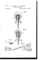
- FIG. 1 is a longitudinal sectional view of the watch pendant, showing the stem at its limit of inward movement.
- Fig. 2 is a longitudinal sectional View of the pendant showing the stem at its limit of movement in the opposite direction.
- Fig. 3 is a detail perspective view showing the various parts detached, the stem, spring retaining device and the washer.
- Fig. 4 is a detail sectional view of an end or head of the watch bow.
- a is the pendant of the watch case formed hollow with the open outer end and the opposite side openings for the ends of the watch bow a', these side openings being located at a point about midway between the ends of the pendant.
- the watch stem having the crown c, secured on its outer end and closing the outer end of the pendant.
- This stem is provided with a shoulder d, between its ends and located between the bow openings in the pendant and the inner end of the pendant.
- e is a washer snugly fitting the interior of the pendant and resting on said shoulder d, of the stem and located beneath, or between, the inner ends of the watch bow and the inner end of the pendant, so that the ends of the bow within the pendant will limit the outward movement of the watch stem by striking said washer.
- the ends of the bow that project into the interior of the pendant are formed of hard metal heads e', provided with exterior annular grooves, and at their outer ends with screw threaded sockets to receive the screw threaded extensions of the ends of the bow proper.
- a spring fastening device is provided for confining the bow and holding the stem in its various positions.
- This device preferably consists of a washerf, placed loosely on the outer portion of the stem, preferably, at the inner surface of the crown, and provided with two pairs of inwardly projecting spring legs or arms g, resting and abutting against the washer.
- Each pair of spring legs or spring forks embraces a bow head and fits in the groove thereof so as to firmly conne the bow in the pendant and yet permit swinging thereof.
- the spring legs press against the bow heads and can be formed with bulges or inclined projections t', at points intermediate of the path traversed by said spring forks during the movement of the stem so that the stem before moving from one position to another should have sufficient force exerted thereon to cause the legs of the spring forks to separate and allow said bulges or projections to pass the bow heads.
- a Watch the pendant, a siem having a shoulder, a washer on said shoulder, the bow having the grooved ends in the pendant above said Washer, a crown on the stem and the washer on the stem above the bow ends provided with the spring legs embracing said bow ends and bearing against said first mentioned washer combined, substantially as set forth.
- a watch pendant In a watch pendant, the combination of a bow, the longitudinally movable stem, the washer on the stem and movable longitudinally therewith and provided with the spring.r legs embracing and fastening the bow and provided with the beveled stops to engage the bow and yieldinglyhold the stem against longitudinal movement.
Landscapes
- Physics & Mathematics (AREA)
- General Physics & Mathematics (AREA)
- Adornments (AREA)
Description
(No Model.)
P. C. ELSBR 8v C. H. CANNIPF.
' WATGHGASB PENDANT.. No. 536,274.
Patented Mar. 26, 1895.
'UNITED STATES PATENT OFFICE.
PETER O. ELSER AND CHARLES II. OANNIFF, OF CONTINENTAL, OHIO.
WATCHCASE-PEN DANT.
SPECIFICATION forming part of Letters Patent No. 536,274, dated March 26, l 895.
Application filed June 20,1894. S'erial No. 515,156. (No model.)
To a/ZZ whom, it may concern,.-
Be it known that we, PETER O. ELSER and CHARLES H. CANNIFF, of Continental, in the county of Putnam and State of Ohio,have invented certain new and useful Improvements in Watches; and we do hereby declare that the following is a full, clear, and exact description of the invention, which will enable others skilled in the art to which it appertains to make and use the same, reference being had to the accompanying drawings, and to the letters of reference marked thereon, which form part of this specification.
This invention relates to certain improvements in watches, and moreparticularly to pendant set watches.
The object of theinvention is to provide an improved, simple, and durable construction for securing watch-bows and stems.
A further object of the invention is to provide an improved simple arrangement and construction of pendant set watches, whereby a minimum number of parts are employed for controlling the movement of the stem and fastening the watch bow.
The invention consists in certain novel features of construction and in combinations of parts more fully and particularly described hereinafter and pointed out in the claims.
Referring to the accompanying drawings:- Figure l, is a longitudinal sectional view of the watch pendant, showing the stem at its limit of inward movement. Fig. 2, is a longitudinal sectional View of the pendant showing the stem at its limit of movement in the opposite direction. Fig. 3, is a detail perspective view showing the various parts detached, the stem, spring retaining device and the washer. Fig. 4, is a detail sectional view of an end or head of the watch bow.
In the drawings, a, is the pendant of the watch case formed hollow with the open outer end and the opposite side openings for the ends of the watch bow a', these side openings being located at a point about midway between the ends of the pendant.
b, is the watch stem having the crown c, secured on its outer end and closing the outer end of the pendant. This stem is provided with a shoulder d, between its ends and located between the bow openings in the pendant and the inner end of the pendant.
e, is a washer snugly fitting the interior of the pendant and resting on said shoulder d, of the stem and located beneath, or between, the inner ends of the watch bow and the inner end of the pendant, so that the ends of the bow within the pendant will limit the outward movement of the watch stem by striking said washer.
The ends of the bow that project into the interior of the pendant are formed of hard metal heads e', provided with exterior annular grooves, and at their outer ends with screw threaded sockets to receive the screw threaded extensions of the ends of the bow proper.
A spring fastening device is provided for confining the bow and holding the stem in its various positions. This device preferably consists of a washerf, placed loosely on the outer portion of the stem, preferably, at the inner surface of the crown, and provided with two pairs of inwardly projecting spring legs or arms g, resting and abutting against the washer. Each pair of spring legs or spring forks embraces a bow head and fits in the groove thereof so as to firmly conne the bow in the pendant and yet permit swinging thereof.
As the spring device just described is clamped between the crown and washer it is obvious that when the stem is moved longitudinally the spring forks slide on the bow heads so that when the stem reachesits limit of outward movement the washer engages the heads of the bow and when the stem reaches its limit of inward movement the stem is limited by the inner end of the pendant and the spring forks move in on the bow heads.
In order to yieldingly hold the stem in its various positions the spring legs press against the bow heads and can be formed with bulges or inclined projections t', at points intermediate of the path traversed by said spring forks during the movement of the stem so that the stem before moving from one position to another should have sufficient force exerted thereon to cause the legs of the spring forks to separate and allow said bulges or projections to pass the bow heads.
IOO
XVe do not wish to limit ourselves to any peculiar construction of bow,but have shown a bow having the movable or hard metal heads so asto prevent undue Wear by reason of the friction with the spring forks.
The extreme simplicity and durability of this invention and the minimum number of parts employed to accomplish the various 0bjects in View are obvious.
It is evident that various changes might be made in the forms, arrangements and constructions of the parts described, without departing from the spirit and scope of our invention. Ilence we do not wish to limit ourselves to the exact construction herein set forth,-but consider ourselves entitled to all such changes as fall Within the spirit and scope of our invention.
Having thus fully described our invention, what we claim as new, and desire to secure by Letters Patent of the United States, is-
1. In a Watch, the pendant, a siem having a shoulder, a washer on said shoulder, the bow having the grooved ends in the pendant above said Washer, a crown on the stem and the washer on the stem above the bow ends provided with the spring legs embracing said bow ends and bearing against said first mentioned washer combined, substantially as set forth.
2. ln a watch pendant, abou' having its ends extended into the pendant,and the longitudinally movable stem provided with the spring legs moving therewith and fastening the bow and yieldingly holding the stem against longitudinal movement., substantially as dcscribed.
3. In a watch pendant, the combination of a bow, the longitudinally movable stem, the washer on the stem and movable longitudinally therewith and provided with the spring.r legs embracing and fastening the bow and provided with the beveled stops to engage the bow and yieldinglyhold the stem against longitudinal movement.
In testimony that we claim the foregoing as our own we ailix our signatures in presence ot' two witnesses.
PETER C. ELSER. CHARLES H. GANNIFF.
Witnesses:
SAMUEL BRETZ, A. J. MCCLURE.
Publications (1)
| Publication Number | Publication Date |
|---|---|
| US536274A true US536274A (en) | 1895-03-26 |
Family
ID=2605035
Family Applications (1)
| Application Number | Title | Priority Date | Filing Date |
|---|---|---|---|
| US536274D Expired - Lifetime US536274A (en) | Watch case-pendant |
Country Status (1)
| Country | Link |
|---|---|
| US (1) | US536274A (en) |
-
0
- US US536274D patent/US536274A/en not_active Expired - Lifetime
Similar Documents
| Publication | Publication Date | Title |
|---|---|---|
| US536274A (en) | Watch case-pendant | |
| US445755A (en) | Bottle-lock | |
| US765139A (en) | Reinforcer for bolts. | |
| US714777A (en) | Snap-hook. | |
| US606997A (en) | Detachable link | |
| US1101868A (en) | Valve and plug-cock. | |
| US1173647A (en) | Bed-corner. | |
| US954885A (en) | Compasses. | |
| US246513A (en) | Frederick w | |
| US1085479A (en) | Umbrella-frame. | |
| US65985A (en) | Improvement in winding watches | |
| US72035A (en) | Improvement in elliptic cabeiage-speing | |
| US1024279A (en) | Switch-throwing device. | |
| US935061A (en) | Hub-attaching device. | |
| US250780A (en) | Service-cock and casing | |
| US1042850A (en) | Gas-regulating valve. | |
| US872971A (en) | Clock-key. | |
| US575123A (en) | Device for adjusting counterbalance-springs of locomotives | |
| US1151446A (en) | Reversible sign. | |
| US989108A (en) | Door-holding means. | |
| US441435A (en) | Watch-case pendant | |
| US556329A (en) | William s | |
| US98733A (en) | Improvement in caps for coffin-nails | |
| US609462A (en) | Watchcase-pendant | |
| US1032407A (en) | Spring. |