US5350294A - Lighter - Google Patents
Lighter Download PDFInfo
- Publication number
- US5350294A US5350294A US08/088,552 US8855293A US5350294A US 5350294 A US5350294 A US 5350294A US 8855293 A US8855293 A US 8855293A US 5350294 A US5350294 A US 5350294A
- Authority
- US
- United States
- Prior art keywords
- push
- lift
- lighter
- locked state
- lighter body
- Prior art date
- Legal status (The legal status is an assumption and is not a legal conclusion. Google has not performed a legal analysis and makes no representation as to the accuracy of the status listed.)
- Expired - Fee Related
Links
- 239000000446 fuel Substances 0.000 claims abstract description 19
- 238000002347 injection Methods 0.000 claims description 4
- 239000007924 injection Substances 0.000 claims description 4
- 238000005452 bending Methods 0.000 claims 3
- 230000002542 deteriorative effect Effects 0.000 abstract description 2
- 238000010586 diagram Methods 0.000 description 19
- 230000000694 effects Effects 0.000 description 6
- 210000003813 thumb Anatomy 0.000 description 4
- 235000019504 cigarettes Nutrition 0.000 description 3
- 210000003811 finger Anatomy 0.000 description 2
- 239000002828 fuel tank Substances 0.000 description 2
Images


Classifications
-
- F—MECHANICAL ENGINEERING; LIGHTING; HEATING; WEAPONS; BLASTING
- F23—COMBUSTION APPARATUS; COMBUSTION PROCESSES
- F23Q—IGNITION; EXTINGUISHING-DEVICES
- F23Q2/00—Lighters containing fuel, e.g. for cigarettes
- F23Q2/16—Lighters with gaseous fuel, e.g. the gas being stored in liquid phase
- F23Q2/164—Arrangements for preventing undesired ignition
Definitions
- the present invention relates to a lighter for lighting cigarettes or like, for example, and, more particularly, to an improvement of a lighter which is equipped with a safety device to prevent small children from carelessly or accidentally igniting the lighter.
- Japanese Examined Patent Publication No. hei 3-501050 U.S. Pat. No. 5,002,482 discloses a lighter equipped with such a safety device.
- This lighter has a safety latch member attached under a push-down member, which is manipulated at the time of ignition, in such a way that the pressing action of the push-down member is selectively permitted by rotating this safety latch member in the proper direction.
- a small child cannot easily ignite the lighter even the child tries to do so.
- Another conventional lighter is disclosed in Japanese Unexamined Patent Publication No. hei 4-363515.
- the conventional structure has the following shortcoming.
- the safety device of the above-described lighter is a manipulator provided separately from the push-down member that is manipulated to ignite the lighter in such a way that the separate manipulator should be manipulated to unlock the push-down member before manipulating the push-down member for ignition.
- the separate manipulator should be manipulated to unlock the push-down member before manipulating the push-down member for ignition.
- two different operating members must be operated separately to ignite the lighter. This demands the user of a troublesome manipulation, thus lowering the operability of the lighter.
- the lighter of the present invention comprises a lighter body for storing fuel; valve means, attached to an upper portion of the lighter body, for stopping injection of the fuel when closed and permitting injection of the fuel when open; ignition means, provided at the upper portion of the lighter body and activatable as needed to ignite the fuel injected by opening of the valve means; lift-up means, arranged rotatable via a rotary shaft at the upper portion of the lighter body and having one end connected to the valve means, for closing the valve means when urged in one direction by an elastic member and opening the valve means when rotated in the opposite direction against urging force of the elastic member; and push-down means, provided movable along the lift-up means on the other end side thereof, a slide position of the push-down means being properly maintained by a relationship with respect to the lighter body or the lift-up means, whereby when the lighter is not in use, the push-down means is kept positioned on the other end side of the lift-up means and has a lower end abutting against the lighter body to set
- the safety device When the lighter is not in use, the safety device is working to lock the lighter. More specifically, in the locked state, the push-down means is kept positioned on the other end side of the lift-up means and its lower end abuts against the lighter body to restrict the downward action. In other words, even when a small child tries to push down the push-down means carelessly, the lower end of the push-down means abuts against the lighter body to restrict the downward action, thereby preventing careless ignition of the light. To unlock the lighter to use it, first, the push-down means is moved along the lift-up means toward one end thereof to release the locked state.
- the push-down means is pushed down to rotate the lift-up means to open the valve means, and at the same time, the ignition means is activated to ignite the fuel injected through the valve means. Accordingly, the user can now light a cigarette or the like.
- the downward action of the push-down means is released, so that the push-down means can returns to the locked state as it moves toward the other end of the lift-up means, which is returning by the urging force of the elastic member, along the lift-up means.
- releasing of the locked state and ignition can both be accomplished merely by manipulating a single operating member: the push-down means, and the lighter automatically returns to the locked state after ignition.
- the operability of the lighter can improved significantly without deteriorating the safety function of the safety device.
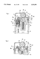
- FIG. 1 is a partly cross-sectional view illustrating a lighter according to a first embodiment of the present invention not in use (locked state);
- FIG. 2 is a partly cross-sectional view illustrating the lighter according to the first embodiment which is unlocked for usage by sliding a push-down member in the nozzle direction;
- FIG. 3 is a partly cross-sectional view of the lighter according to the first embodiment, illustrating that a file is rotated and the push-down member is pushed down for ignition;
- FIG. 4 is a plan view of the first embodiment, showing the relationship between the push-down member and a lift-up lever when the lighter is not in use (locked state);
- FIG. 5 is a plan view of the first embodiment, showing the relationship between the push-down member and the lift-up lever when the push-down member is slid in the nozzle direction to unlock the lighter for usage;
- FIG. 6 is a plan view of the first embodiment, showing the relationship between the push-down member and the lift-up lever when the file is rotated and the push-down member is pushed down for ignition;
- FIG. 7 is a plan view of the push-down member of the first embodiment
- FIG. 8 is a front view of the push-down member of the first embodiment
- FIG. 9 is a bottom view of the push-down member of the first embodiment.
- FIG. 10 is a side view of the push-down member of the first embodiment
- FIG. 11 is a plan view of the lid of a lighter body of the first embodiment
- FIG. 12 is a side view of the lid of the lighter body of the first embodiment
- FIG. 13 is a rear view of the lid of the lighter body of the first embodiment
- FIG. 14 is a cross section of the lid of the lighter body of the first embodiment
- FIG. 15 is a plan view of the lift-up lever of the first embodiment
- FIG. 16 is a side view of the lift-up lever of the first embodiment
- FIG. 17 is a partly cross-sectional view illustrating a lighter according to a second embodiment of the present invention not in use (locked state);
- FIG. 18 is a partly cross-sectional view of the lighter according to the second embodiment, illustrating that further downward movement of a push-down member is restricted;
- FIG. 19 is a partly cross-sectional view illustrating the lighter according to the second embodiment which is unlocked for usage by sliding a push-down member in the nozzle direction;
- FIG. 20 is a partly cross-sectional view of the lighter according to the second embodiment, illustrating that a file is rotated and the push-down member is pushed down for ignition;
- FIG. 21 is a plan view of the lid of a lighter body of the second embodiment
- FIG. 22 is a side view of the lid of the lighter body of the second embodiment
- FIG. 23 is a cross section view of the lid of the lighter body of the second embodiment.
- FIG. 24 is a plan view of the lift-up lever of the second embodiment
- FIG. 25 is a side view of the lift-up lever of the second embodiment
- FIG. 26 is a cross-sectional view of the lift-up lever of the second embodiment
- FIG. 27 is a plan view of the push-down member of the second embodiment
- FIG. 28 is a side view of the push-down member of the second embodiment
- FIG. 29 is a cross-sectional view of the push-down member of the second embodiment.
- FIG. 30 is a rear view of the push-down member of the second embodiment
- FIG. 31 is a plan view of the second embodiment, showing the push-down member attached to the lift-up lever;
- FIG. 32 is a side view of the second embodiment, showing the push-down member attached to the lift-up lever and its relationship with a coil spring;
- FIG. 33 is a cross section of the second embodiment taken along XXXIII--XXXIII in FIG. 31;
- FIG. 34 is a side view of a third embodiment of the present invention not in use (locked state), showing the relationship between a lift-up lever and auxiliary wheels;
- FIG. 35 is a side view of the third embodiment, showing the relationship between a lift-up lever and auxiliary wheels when in an unlocked state;
- FIG. 36 is a side view of a fourth embodiment of the present invention not in use (locked state), showing the relationship between a lift-up lever and auxiliary wheels;
- FIG. 37 is a cross-sectional view of a fifth embodiment of the present invention, showing the relationship between an engage portion and an engage pawl, which are provided to prevent an easy unlocking manipulation;
- FIG. 38 is a cross-sectional view illustrating part of a lighter according to a sixth embodiment of the present invention.
- FIG. 39 is a partly cross-sectional view illustrating part of a lighter according to a seventh embodiment of the present invention in a locked state
- FIG. 40 is a partly cross-sectional view illustrating part of the lighter according to the seventh embodiment when unlocked
- FIG. 41 is a plan view of the seventh embodiment, showing the relationship between a lift-up lever and a push-down member;
- FIG. 42 is a cross-sectional view of the seventh embodiment, showing the relationship between the lift-up lever and the push-down member;
- FIG. 43 is a partly cross-sectional view illustrating part of a lighter according to an eighth embodiment of the present invention in a locked state
- FIG. 44 is a partly cross-sectional view illustrating part of the lighter according to the eighth embodiment when unlocked.
- FIG. 45 is a plan view of the eighth embodiment, showing the relationship between a lift-up lever and a push-down member.
- FIG. 46 is a cross-sectional view of the eighth embodiment, showing the relationship between the lift-up lever and the push-down member.
- a lighter body 1 comprises a hollow case 1a and a lid 1b attached to the top edge of this case 1a.
- a fuel tank 3 which retains fuel 5.
- a nozzle attachment 7 is formed on the left-hand side of the lighter body 1 in FIG. 1.
- a nozzle 9 is attached to this nozzle attachment 7.
- a fuel supply tube 11 is provided under the nozzle attachment 7, with its lower end extending to the bottom of the fuel tank 3.
- the nozzle 9 is seated on a seat portion 15 formed on the nozzle attachment 7, by a coil spring 13.
- the nozzle 9 and the seat portion 15 constitute valve means.
- a flint 17 is disposed at the upper portion of the lighter body 1 on the right-hand side in the diagrams while being urged upward by a coil spring 19.
- a rotary file 21 Located above the flint 17 is a rotary file 21 on both sides of which auxiliary wheels 25 are disposed rotatable via a support shaft 23.
- a rotary file 21 As the rotary file 21 is rotated in the direction of an arrow a through the auxiliary wheels 25, it grinds the flint 17 to make sparks to thereby ignite the gas injected from the nozzle 9.
- the flint 17, rotary file 21 and auxiliary wheels 25 constitute ignition means.
- a lift-up lever 27 as lift-up means is disposed at the upper portion of the lighter body 1 in such a way as to be rotatable in the direction of an arrow b.
- This lift-up lever 27 is structured as shown in FIGS. 15 and 16.
- a nozzle engage portion 29 which engages with a neck 9a of the nozzle 9 from below.
- the lift-up lever 27 has a pair of extending rail arms 31a and 31b on the right-hand side (in the diagrams) of the nozzle engage portion 29.
- Rotary shafts 33a and 33b are protrusively provided at the proximal end portions of both rail arms 31a and 31brespectively.
- the lift-up lever 27 is supported rotatable on the lid 1b of the lighter body 1 via those rotary shafts 33a and 33b.
- the rail arm 31a has an engage pawl 35a formed thereon as a first projection and another engage pawl 37a formed closer to the distal end as a second engage pawl.
- the rail arm 31b has engage pawls 35b and 37b formed thereon.
- the rail arms 31a and 31b respectively have inclined surfaces 39a and 39 b each formed at the distal end and at the bottom.
- a push-down member 41 as push-down means is separately and movably attached to the top of the rail arms 31a and 31b on the right-hand side thereof in the diagram.
- the push-down member 41 has a structure as shown in FIGS. 7 through 10.
- the push-down member 41 has an operating portion 41a which is to be operated by a thumb of a user and a projection 41b protruding from the bottom of the operating portion 41a. (although this operating portion 41a is normally operated by the user's thumb, it may of course be operated by a different finger.)
- a flange 41c is formed at the bottom of the projection 41b.
- a projection 43 is protrusive provided at the back of the flange 41c.
- This projection 43 has an slanted surface inclining toward the nozzle 9 as shown in FIG. 10.
- the push-down member 41 further has a pair of engage recesses 45a and 45b as a first engage portion and inclined surfaces 47a and 47b at the bottom side on the left and right sides, as shown in FIG. 9.
- the push-down member 41 also has engage portions 49a and 49b provided at the distal end as second engage portions.
- the lid 1b of the lighter body 1 has a pair of file stays 51a and 51b between which the aforementioned rotary file 21 and auxiliary wheels 25 are supported rotatably.
- a retainer 53 for retaining the flint 17 and coil spring 19.
- a pair of restoring projections 55a and 55b as restoring means are protrusively provided on the right-hand end portion (in the diagrams) of the lid 1b.
- Space 57 is formed on the left-hand side of those projections 55a and 55b in the diagrams, with a stopper portion 59 formed on the right-hand side (in the diagrams) in the space 57.
- the lighter is in the state shown in FIGS. 1 and 4.
- the nozzle 9 is pressed against the seat portion 15 by the force of the coil spring 13 so that the seat portion 15 is closed.
- the push-up lever 27 is urged in the counterclockwise direction in FIG. 1 and is staying nearly horizontal.
- the pressing member 41 is shifted rightward in FIG. 1, with the projection 43 abutting on the stopper portion 59 of the lid 1b. In other words, even if the pressing member 41 is pressed down through its operating portion 41athe projection 43 hits against the stopper portion 59 to prevent the pressing member 41 from being pushed further downward (locked state).
- FIG. 4 The relationship between the pressing member 41 and push-up lever 27 at that time is illustrated in FIG. 4. That is, the engage pawls 35a and 35b of the rail arm 31a and 31b are in engagement with the engage recesses 45a and 45b of the pressing member 41. This engagement restricts further movement of the pressing member 41 and prevents the member 41 from disengaging from the push-up lever 27.
- the auxiliary wheels 25 and the rotary file 21 are rotated, and the push-down member 41 is pushed down at the same time.
- the downward action of the push-down member 41 rotates the lift-up lever 27 to the state shown in FIG. 3, so that the nozzle 9 rises against the force of the coil spring 13.
- gas is injected upward from the tip of the nozzle 9.
- the rotation of the rotary file 21 grinds the flint 17 to make sparks so that the gas is ignited.
- the downward movement of the push-down member 41 also pushes down the rail arm pair 31a and 31b.
- the rail arms 31a and 31b respectively hit against the restoring projections 55a and 55b at that time, the rail arms 31a and 31b are bent inward.
- the lift-up lever 27 tries to rotate back first by the urging force of the coil spring 13.
- the push-down member 41 tries to move along the rail arm pair 31a and 31b in the direction opposite to the nozzle 9.
- the engage pawls 37a and 37b of those arms 31a and 31b will not engage with the engage portions 49a and 49b of the push-down member 41. Therefore, the push-down member 41 automatically returns to the state shown in FIG. 1. That is, the push-down member 41 returns to the initial locked state.
- this embodiment exhibits the following effects.
- releasing of the locked state and ignition can both be accomplished merely by manipulating a single operating member, namely, the push-down member 41. Therefore, this embodiment can significantly improve the operability of the lighter as compared with the conventional lighter, which requires one operating member to release the locked state and another operating member for ignition. This improvement will not deteriorate the safety function of the safety device, so that the lighter will not be ignited by careless or accidental manipulation by a small child or the like.
- the lighter and the lighter automatically returns to the locked state after ignition and will not be left unlocked, thus securing sufficient safety.
- the lift-up lever 27 as lift-up means in this embodiment has a structure as shown in FIGS. 24 through 26.
- a nozzle engage portion 61 which engages with the neck 9a of the nozzle 9 from below.
- the lift-up lever 27 has a frame portion 63 formed on the right-hand of the nozzle engage portion 61 side in the diagrams.
- Rotary shafts 65a and 65b are protrusively provided at the proximal end portion of the frame portion 63.
- the lift-up lever 27 is supported rotatable on the lid 1b of the lighter body 1 via those rotary shafts 65a and 65b.
- Step portions 67a and 67b are formed in a widthwise middle portion of the frame portion 63 in the diagrams. Both inner side surfaces of the frame portion 63 located on the right-hand side of the step portions 67a and 67b in the diagrams serve as guide surfaces 69a and 60 brespectively.
- the push-down member 41 as push-down means is separately and movably attached to the top of the frame portion 63 of the lift-up lever 27.
- This push-down member 41 has a structure as shown in FIGS. 27 through 30.
- the push-down member 41 has an operating portion 71 which is to be operated by a thumb of a user and a projection 73 protruding from the bottom of the operating portion 71. (although this operating portion 71 is normally operated by the user's thumb, it may of course be operated by a different finger.)
- An engage pawl 75 is formed in front of the operating portion 71.
- the projection 73 has an inclined surface 77 formed on the front side, with a projection 79 protruding from a nearly middle portion of the inclined surface 77.
- Guide members 81a and 81b are formed at the bottom of the projection 73 on the left- and right-hand sides thereof. The bottom of the projection 73 serves as a stop portion 80.
- the push-down member 41 having the above-described structure are engaged with the inner side of the frame portion 63 of the lift-up lever 27 in the manner shown in FIGS. 31 through 33. More specifically, the push-down member 41 is inserted into the left portion of the frame portion 63 of the lift-up lever 27 from the above and is then slid rightward (see FIGS. 31 and 32) for attachment. Consequently, the guide members 81a and 81b of the push-down member 41 come into engagement with the bottom surfaces of the frame portion 63 at the bottoms of the guide surfaces 69a and 60bthus preventing the push-down member 41 from coming off upward from the frame portion 63. The bottom surfaces of the left and right side portions of the operating portion 71 are in engagement with the top surfaces of the frame portion 63 at the tops of the guide surfaces 69a and 60b.
- a coil spring 83 as elastic means is disposed in the space 57 in such a manner that the projection 79 of the push-down member 41 is fitted in the upper end portion of the coil spring 83 whose top end is abutting on the inclined surface 77.
- the push-down member 41 is set to be always urged upward as well as rearward.
- the urging acts not only in the upward direction but also in the rearward direction because of the presence of the inclined surface 77. That is, when the force of the coil spring 83 acts on the inclined surface 77, this force urges the push-down member 41 rearward through the inclined surface 77 as well as in the upward direction.
- an engage portion 85 is formed at the top and in the center portion of the lid 1b.
- the engage pawl 75 of the push-down member 41 is selectively engaged with this engage portion 85, and when the engagement is established, the unlocked state is maintained.
- the other structure of the lid 1b is the same as that of the first embodiment.
- the lighter when not in use will be described.
- the lighter is in the state as shown in FIG. 17; the right end (in the diagram) of the lift-up lever 27 is rotated slightly counterclockwise as compared with that of the first embodiment.
- the stop portion 80 abuts on the stopper portion 59 of the lid 1b as shown in FIG. 18, thereby restricting the further downward movement of the push-down member 41.
- the restriction of the downward movement of the push-down member 41 thus restricts the clockwise rotation of the lift-up lever 27 in the diagram. That is, the lighter is locked so that even if a small child carelessly presses the push-down member 41 down, the lighter will never be ignited.
- the ignition operation starts with the unlocking of the lighter.
- the push-down member 41 is pressed down to the state shown in FIG. 18, and is then pushed forward (in the direction of the nozzle 9). Accordingly, the push-down member 41 slides in the direction of the nozzle 9 along the frame portion 63 of the lift-up lever 27.
- the engage pawl 75 of the push-down member 41 thus passes under the engage portion 85 of the lid 1b without any interference.
- the push-down member 41 comes to the state as shown in FIG.
- the inclined surface 77 of the push-down member 41 effectively assists the urging action of the coil spring 83. More specifically, since the top end of the coil spring 83 abuts on the inclined surface 77 so that part of the spring force will act rearward, when the pressure on the push-down member 41 is released, the push-down member 41 surely slides rearward while moving upward to return to the initial position.
- this embodiment also produces the same effect as the first embodiment. That is, releasing of the locked state and ignition can both be accomplished merely by manipulating a single operating member, namely, the push-down member 41. Therefore, this embodiment can significantly improve the operability of the lighter by the user. This improvement will not deteriorate the safety function of the safety device, so that the lighter will not be ignited by careless or accidental manipulation by a small child or the like.
- a third embodiment will be described below referring to FIGS. 34 and 35.
- a plurality of projections 87 serving as a stopper are formed around the auxiliary wheels 25.
- the projections 87 are provided in this embodiment.
- the projections 87 of the auxiliary wheels 25 are set apart from the top of the lift-up lever 27, as shown in FIG. 35. This permits the auxiliary wheels 25 and thus the file 21 to rotate.
- Ratchets 93 are formed on the outer surfaces of the auxiliary wheels 25, and ratchets 95 are likewise formed on the top of the lift-up lever 27.
- the ratchets 93 of the auxiliary wheels 25 are in engagement with the ratchets 95 of the lift-up lever 27, thereby surely restricting accidental rotation of the auxiliary wheels 25 and thus the rotation of the file 21.
- a projection 75a is provided on the engage pawl 75 of the push-down member 41, while a projection 85a is provided on the engage portion 85 of the lid 1b.
- the reason for the provision of those projections 75a and 85a is as follows. As explained in the description of the second embodiment, to use the lighter, the push-down member 41 is pushed downward first, and is then slid forward to unlock the lighter. But, there is a possibility that this unlocking is accomplished spontaneously by pushing the push-down member 41 obliquely downward (in the direction of an arrow A in the diagram). This is not sufficient to prevent a small child from carelessly or accidentally ignite the lighter.
- the projections 75a and 85a are provided to prevent the unlocking of the lighter by the application of the obliquely-downward pressure on the push-down member 41.
- the projection 75a of the engage pawl 75 hits against the projection 85a of the engage portion 85 to restrict further movement of the push-down member 41, thus preventing the lighter from being unlocked. It is thus possible to surely prevent small children from accidentally ignite the lighter.
- a leaf spring 101 is used for the coil spring 83.
- This leaf spring 101 bends in the direction of an arrow B in the diagram.
- the force of the leaf spring 101 returning to the original position from the bent state is also directed obliquely upward, and thus serves to set back the push-down member 41 rearward as well as upward. Accordingly, this structure can provide the same effect as the first embodiment.
- a seventh embodiment will be described below referring to FIGS. 39 through 42.
- the first engage pawls 35a and 35b are omitted from the lift-up lever 27 in the first embodiment, as shown in FIG. 41.
- engage portions 103a and 103b are formed at the bottom and on the left and right sides of the operating portion 71 of the push-down member 41 in the second embodiment, so that those engage portions 103a and 103b engage with the second engage pawls 37a and 37b of the lift-up lever 27.
- the push-down member 41 is pushed down to the position shown in FIG. 39 and is then slid forward.
- the push-down member 41 is slid while the pair of rail arms 31a and 31b of the lift-up lever 27 are bent inward.
- the engage pawl 75 of the push-down member 41 engages with the engage portion 85 of the lid 1bholding the push-down member 41 at the slid position. That is, the locked state is released and the lighter is kept unlocked. Then, the auxiliary wheels 25 are rotated and the push-down member 41 is moved further downward.
- This action rotates the lift-up lever 27 to lift up the nozzle 9, injecting gas, which will be burned by the sparks produced by the file 21 rotating in contact with the flint 17.
- the lift-up lever 27 rotates back and the push-down member 41 moves upward and, at the same time, is urged rearward to return to the original position by the returning force of the rail arms 31a and 31b that has been bend inward.
- This structure can also provide the same effect as the other embodiments.
- FIGS. 43 through 46 An eighth embodiment will be described below referring to FIGS. 43 through 46.
- the inclined surface on the bottom side of the push-down member 41 in the seventh embodiment is omitted so that the push-down member 41 has a flat bottom, and the coil spring 83 used in the second embodiment is also used.
- the force of the coil spring 83 acts only to lift up the push-down member 41 and the rearward returning of the push-down member 41 is forced by the rail arms 31a and 31b of the lift-up lever 27 as per the seventh embodiment. That is, the push-down member 41 is returned rearward by the restoring force of the rail arms 31a and 31b that has been bent inward by the forward sliding of the push-down member 41.
- This embodiment can also provide the same effect as the above-described individual embodiments.
- the present invention is not limited to the above-described embodiments. While a flint is used as ignition means in each embodiment, this invention can also be applied to a so-called electronic lighter. Further, the valve means is in no way limited to the illustrated type. Therefore, the present examples and embodiments are to be considered as illustrative and not restrictive and the invention is not to be limited to the details given herein, but may be modified within the scope of the appended claims.
Landscapes
- Engineering & Computer Science (AREA)
- Chemical & Material Sciences (AREA)
- Combustion & Propulsion (AREA)
- Mechanical Engineering (AREA)
- General Engineering & Computer Science (AREA)
- Lighters Containing Fuel (AREA)
Applications Claiming Priority (2)
| Application Number | Priority Date | Filing Date | Title |
|---|---|---|---|
| JP5-044632 | 1993-02-09 | ||
| JP5044632A JPH06235518A (ja) | 1993-02-09 | 1993-02-09 | ライター |
Publications (1)
| Publication Number | Publication Date |
|---|---|
| US5350294A true US5350294A (en) | 1994-09-27 |
Family
ID=12696806
Family Applications (1)
| Application Number | Title | Priority Date | Filing Date |
|---|---|---|---|
| US08/088,552 Expired - Fee Related US5350294A (en) | 1993-02-09 | 1993-07-09 | Lighter |
Country Status (5)
| Country | Link |
|---|---|
| US (1) | US5350294A (de) |
| EP (1) | EP0611096A3 (de) |
| JP (1) | JPH06235518A (de) |
| AU (1) | AU664008B2 (de) |
| CA (1) | CA2114772A1 (de) |
Cited By (6)
| Publication number | Priority date | Publication date | Assignee | Title |
|---|---|---|---|---|
| US5839892A (en) * | 1996-03-26 | 1998-11-24 | Hwang; Ing Feng | Electronic lighter with a safety device |
| US5971751A (en) * | 1997-06-05 | 1999-10-26 | Chun Ching Yeh | Safety apparatus of a piezoelectric lighter |
| US6039561A (en) * | 1998-02-23 | 2000-03-21 | Lei; Hou Chong | Safety piezo-electric lighter |
| US6102689A (en) * | 1998-09-29 | 2000-08-15 | Man; Aman Chung Kai | Push button safety lighter |
| US9734378B2 (en) | 2008-08-20 | 2017-08-15 | John Gibson Enterprises, Inc. | Portable biometric lighter |
| US10502419B2 (en) | 2017-09-12 | 2019-12-10 | John Gibson Enterprises, Inc. | Portable biometric lighter |
Families Citing this family (7)
| Publication number | Priority date | Publication date | Assignee | Title |
|---|---|---|---|---|
| FR2736142B1 (fr) * | 1995-06-28 | 1997-08-14 | Cricket Sa | Briquet a gaz comportant un systeme d'allumage de securite |
| US6095795A (en) * | 1999-05-03 | 2000-08-01 | Potskhishvili; David Vakhtangovich | Gas lighter with safety device |
| US6129543A (en) * | 1999-05-03 | 2000-10-10 | Potskhishvili; David Vakhtangovich | Gas lighter with safety device |
| US6053727A (en) * | 1999-08-24 | 2000-04-25 | Potskhishvili; David Vakhtangovich | Gas lighter with safety device |
| GB2409018A (en) * | 2003-12-09 | 2005-06-15 | Jieming Guan | Child proof safety lighter |
| GB2429512A (en) | 2005-08-25 | 2007-02-28 | Swedish Match Lighters Bv | A Child Resistant Roll-and-Press Lighter |
| KR200485452Y1 (ko) * | 2017-06-24 | 2018-01-11 | 하나로인터내셔널 (주) | 가스 라이터 |
Citations (2)
| Publication number | Priority date | Publication date | Assignee | Title |
|---|---|---|---|---|
| US5165885A (en) * | 1991-10-17 | 1992-11-24 | Masayuki Iwahori | Safety mechanism for a lighter |
| US5205729A (en) * | 1991-11-01 | 1993-04-27 | Masayuki Iwahori | Safety mechanism for a lighter |
Family Cites Families (1)
| Publication number | Priority date | Publication date | Assignee | Title |
|---|---|---|---|---|
| JPH0492142U (de) * | 1990-11-30 | 1992-08-11 |
-
1993
- 1993-02-09 JP JP5044632A patent/JPH06235518A/ja active Pending
- 1993-07-09 US US08/088,552 patent/US5350294A/en not_active Expired - Fee Related
-
1994
- 1994-02-02 EP EP94300785A patent/EP0611096A3/en not_active Withdrawn
- 1994-02-02 CA CA002114772A patent/CA2114772A1/en not_active Abandoned
- 1994-02-04 AU AU54920/94A patent/AU664008B2/en not_active Ceased
Patent Citations (2)
| Publication number | Priority date | Publication date | Assignee | Title |
|---|---|---|---|---|
| US5165885A (en) * | 1991-10-17 | 1992-11-24 | Masayuki Iwahori | Safety mechanism for a lighter |
| US5205729A (en) * | 1991-11-01 | 1993-04-27 | Masayuki Iwahori | Safety mechanism for a lighter |
Cited By (11)
| Publication number | Priority date | Publication date | Assignee | Title |
|---|---|---|---|---|
| US5839892A (en) * | 1996-03-26 | 1998-11-24 | Hwang; Ing Feng | Electronic lighter with a safety device |
| US5971751A (en) * | 1997-06-05 | 1999-10-26 | Chun Ching Yeh | Safety apparatus of a piezoelectric lighter |
| USRE42750E1 (en) | 1997-06-05 | 2011-09-27 | Calico Brands, Inc. | Safety apparatus of a piezoelectric lighter |
| US6039561A (en) * | 1998-02-23 | 2000-03-21 | Lei; Hou Chong | Safety piezo-electric lighter |
| US6102689A (en) * | 1998-09-29 | 2000-08-15 | Man; Aman Chung Kai | Push button safety lighter |
| US9734378B2 (en) | 2008-08-20 | 2017-08-15 | John Gibson Enterprises, Inc. | Portable biometric lighter |
| US9940499B2 (en) | 2008-08-20 | 2018-04-10 | John Gibson Enterprises, Inc. | Portable biometric lighter |
| US10502419B2 (en) | 2017-09-12 | 2019-12-10 | John Gibson Enterprises, Inc. | Portable biometric lighter |
| US10969102B2 (en) | 2017-09-12 | 2021-04-06 | John Gibson Enterprises, Inc. | Portable biometric lighter |
| US11774096B2 (en) | 2017-09-12 | 2023-10-03 | John Gibson | Portable biometric lighter |
| US12298005B2 (en) | 2017-09-12 | 2025-05-13 | John Gibson | Portable biometric lighter |
Also Published As
| Publication number | Publication date |
|---|---|
| JPH06235518A (ja) | 1994-08-23 |
| EP0611096A3 (en) | 1996-04-10 |
| EP0611096A2 (de) | 1994-08-17 |
| AU5492094A (en) | 1994-08-11 |
| CA2114772A1 (en) | 1994-08-10 |
| AU664008B2 (en) | 1995-10-26 |
Similar Documents
| Publication | Publication Date | Title |
|---|---|---|
| US5350294A (en) | Lighter | |
| US5378143A (en) | Safety lighter | |
| US5368473A (en) | Gas lighter with safety device | |
| US6095796A (en) | Double-button piezoelectric child-resistant cigarette lighter | |
| JP2784966B2 (ja) | 安全装置付ガスライター | |
| US5186618A (en) | Gas lighter with safety device | |
| US7175425B2 (en) | Child-resistant utility lighter incorporating a cam mechanism and a lever spring lock | |
| US6682341B2 (en) | Child resistant actuator for piezoelectric lighter | |
| US5417571A (en) | Child resistant lighter | |
| US5788474A (en) | Safety lighter | |
| US5607295A (en) | Safety lock cigarette lighter | |
| US6318992B1 (en) | Slide-safety button child-resistant utility lighter | |
| US5288226A (en) | Cigarette lighter | |
| US5387101A (en) | Cigarette lighters | |
| JP3523451B2 (ja) | ガスライター | |
| US6102689A (en) | Push button safety lighter | |
| US5332387A (en) | Cigarette lighter | |
| CA2463984C (en) | Igniter | |
| US6666678B2 (en) | Multi-button piezoelectric child-resistant cigarette lighter | |
| US6422860B2 (en) | Double-button piezoelectric child-resistant cigarette lighter | |
| US6808386B2 (en) | Gas lighter with a locking device | |
| JPH0658538A (ja) | 安全装置付ガスライター | |
| JP3110920B2 (ja) | ライター用安全装置 | |
| US6299434B1 (en) | Double-button piezoelectric child-resistant cigarette lighter | |
| JP3814192B2 (ja) | 点火器 |
Legal Events
| Date | Code | Title | Description |
|---|---|---|---|
| FEPP | Fee payment procedure |
Free format text: PAYOR NUMBER ASSIGNED (ORIGINAL EVENT CODE: ASPN); ENTITY STATUS OF PATENT OWNER: SMALL ENTITY |
|
| REMI | Maintenance fee reminder mailed | ||
| LAPS | Lapse for failure to pay maintenance fees | ||
| FP | Lapsed due to failure to pay maintenance fee |
Effective date: 19980927 |
|
| STCH | Information on status: patent discontinuation |
Free format text: PATENT EXPIRED DUE TO NONPAYMENT OF MAINTENANCE FEES UNDER 37 CFR 1.362 |