US5341869A - Top supported high temperature heating surface module with permanent structural frame - Google Patents
Top supported high temperature heating surface module with permanent structural frame Download PDFInfo
- Publication number
- US5341869A US5341869A US08/092,307 US9230793A US5341869A US 5341869 A US5341869 A US 5341869A US 9230793 A US9230793 A US 9230793A US 5341869 A US5341869 A US 5341869A
- Authority
- US
- United States
- Prior art keywords
- vertical members
- level
- arrangement according
- temporary
- vertical
- Prior art date
- Legal status (The legal status is an assumption and is not a legal conclusion. Google has not performed a legal analysis and makes no representation as to the accuracy of the status listed.)
- Expired - Fee Related
Links
- 238000010438 heat treatment Methods 0.000 title claims abstract description 19
- WYTGDNHDOZPMIW-RCBQFDQVSA-N alstonine Natural products C1=CC2=C3C=CC=CC3=NC2=C2N1C[C@H]1[C@H](C)OC=C(C(=O)OC)[C@H]1C2 WYTGDNHDOZPMIW-RCBQFDQVSA-N 0.000 claims description 3
- 229910000831 Steel Inorganic materials 0.000 description 6
- 239000010959 steel Substances 0.000 description 6
- 238000011084 recovery Methods 0.000 description 3
- 229910000746 Structural steel Inorganic materials 0.000 description 1
- 230000004888 barrier function Effects 0.000 description 1
- 238000011068 loading method Methods 0.000 description 1
- 238000000034 method Methods 0.000 description 1
- 230000006641 stabilisation Effects 0.000 description 1
- 238000011105 stabilization Methods 0.000 description 1
- 230000007704 transition Effects 0.000 description 1
Images


Classifications
-
- F—MECHANICAL ENGINEERING; LIGHTING; HEATING; WEAPONS; BLASTING
- F22—STEAM GENERATION
- F22B—METHODS OF STEAM GENERATION; STEAM BOILERS
- F22B37/00—Component parts or details of steam boilers
- F22B37/001—Steam generators built-up from pre-fabricated elements
-
- F—MECHANICAL ENGINEERING; LIGHTING; HEATING; WEAPONS; BLASTING
- F22—STEAM GENERATION
- F22B—METHODS OF STEAM GENERATION; STEAM BOILERS
- F22B37/00—Component parts or details of steam boilers
- F22B37/02—Component parts or details of steam boilers applicable to more than one kind or type of steam boiler
- F22B37/24—Supporting, suspending or setting arrangements, e.g. heat shielding
- F22B37/242—Supporting, suspending or setting arrangements, e.g. heat shielding for bottom supported water-tube steam generators
Definitions
- the present invention relates in general to heat exchangers and in particular to a new and useful modular arrangement for the shipment and assembly of heat exchanger units.
- HRSG Heat Recovery Steam Generators
- HRSG's have usually consisted of a vertically oriented heat exchanger comprising spirally-finned tubes located inside an externally supported box type structure.
- High temperature turbine exhaust gas passes through the box and over the tubes in order to recover the heat from the gas.
- Known modular arrangements typically comprise a finned tube heating surface that is bundled complete with top and bottom headers. For ease of handling, these modular shop assembled packages are assembled with an integral shipping truss assembly built of commercially available structural steel shapes.
- the finned tube heating surface is shipped in a horizontal position and rotated at the erection site to a vertical orientation.
- support for the heating surface is normally provided by base frame steel which comprises a part of the shipping truss assembly.
- the known box type structure designs comprise internally insulated and lined casing panels which incorporate a cold casing design. These panels can be either a part of the shipping module or they can be installed after the HRSG pressure part modules have been placed in their final position. Column steel attached to these panels provides the overall strength and stability for the total HRSG structure by providing side to side as well as fore and aft restraint against potential loadings which could occur as a result of wind and seismic conditions.
- the present invention provides for an arrangement for containing a heating unit therein which comprises a top and bottom opposite the top.
- Two vertical members are connected to the top and the bottom and are spaced a distance from each other.
- At least one level is rotatably connected between the vertical members.
- a plurality of support rods are connected to the top and the level.
- Temporary supports are removably attached to the top, the vertical members and the bottom.
- the heating unit extends between the top and the bottom through the level and is confined by the vertical members and the support rods.
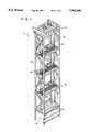
- FIG. 1 is a perspective view of a module according to the present invention
- FIG. 2 is a view of FIG. 1 without temporary supports
- FIG. 3 is a view illustrating the module of FIG. 1 positioned in a permanent arrangement
- FIG. 4 is a view illustrating a section of FIG. 1;
- FIGS. 5a are views illustrating the erection procedure of 5b, 5c the structure in FIG. 1;
- FIG. 6 is a view illustrating a level of FIG. 1.
- the present invention is an arrangement for the shipment and assembly of heat exchanger units for a heat recovery steam generator.
- the heating surfaces of the heat recovery steam generator are contained within a structural frame comprising a combination of permanent and temporary steel members.
- the present invention comprises a module 12 which is moved and handled in a horizontal position (FIG. 5a) and having a top lifting means 80 and a base lifting means 90.
- the present invention is lifted into a vertical position (FIG. 5b) for being set into its final position (FIG. 5c).
- FIG. 1 shows the module 12 comprising permanent vertical members connected to a top 14 and a bottom 16.
- a plurality of levels 18 are rotatably connected to the permanent vertical members 20 by pins 32.
- the module 12 also comprises temporary vertical frames 21 connected to the top 14 and the bottom 16 opposite the permanent vertical members 20.
- the temporary members 21 are removably attached to the top 14 and the bottom 16 once the module 12 is lifted into its final position (FIG. 5c).
- the module 12 also comprises other temporary members for providing stability during shipment, handling and erection. These temporary members include a junction 28 removably attached to the permanent members 20 and the temporary members 21 and temporary diagonal truss members 50 connected to the junctions 28 between the levels 18. Temporary base members 33 are also used to stabilize the bottom 16 of the module 12 during shipment and handling.
- FIG. 2 shows the module 12 without its temporary supporting members.
- the module 12, at its final erection site (FIG. 5c), is attached to top steel 70 at the top 14 of the module 12.
- the module 12 also includes permanent diagonal members 55 connected between the permanent vertical members 20 and between each level 18 of the module 12.
- the top 14 comprises top headers 96.
- a plurality of support rods 5 are connected to the top 14 at the headers 96 and are connected to each level 18 of the module 12.
- the heating surfaces i.e. spiral-finned tubes 15, extend through each level 18 from the top 14 to the bottom 16.
- a plurality of intermediate tubes 17 also extend through each level 18 from the top 14 to the bottom 16 as shown in FIG. 4.
- FIG. 6 illustrates a level 18 rotatably attached by pins 32 to the permanent vertical members 20.
- Each level 18 comprises a structural beam 39 rotatably connected to the vertical members 20 and intermediate bracing 31 rotatably connected to the vertical members 20 and the structural beam 39.
- the intermediate bracing 31 also includes a plurality of rectangular tubes 35 and serpentine bars 36 between the rectangular tubes 35.
- the spiral-finned heating tubes 15 are arranged through the level 18 between the rectangular tubes 35 and against the serpentine bar 36.
- the level 18 also includes a diagonal internal truss 34 connected to the structural beam 39 and the intermediate bracing 31.
- the modules 12 are arranged adjacent each other within a casing 10 supported by main vertical columns 23 and a main base 25.
- a fore and aft tie 52 is provided from adjacent bottom supported modules 13, to provide lateral restraint to the top supported module 12 in the direction of gas flow through the modules 12, 13.
- barriers 58 are attached between the modules 12 at the intermediate bracing 31 in order to block gas lanes or passages between the modules 12.
- the pins 32 permit the levels 18 to rotate due to vertical differential thermal expansions between the front and the rear of the module 12.
- the diagonal truss members 34 are formed integral with the intermediate bracing 31 in order to provide side-to-side stabilization for the module 12 as shown in FIG. 6.
- the module 12 restrains the heating sections 15 laterally at the intermediate locations 18 by holding the heating sections 15 in place in order to prevent excessive vibration during operation.
- the present invention allows for the heating surface to be packaged in a structural container which enables shipping and handling in a horizontal position and uprighting of the module 12 to a vertical position.
- the module 12 is independent and free standing and thus is easy to erect and transition from the bottom support to the top support.
- the modules 12 are set into place before side casings 10 or top steel 70, as shown in FIG. 3, are set in place which simplifies erection of the module 12.
- the remaining permanent steel, which is part of the shipping frame, is used to secure the fore and aft ties 52 (FIGS. 2 and 3) and miscellaneous attachments which are necessary for operation.
Landscapes
- Engineering & Computer Science (AREA)
- Physics & Mathematics (AREA)
- Thermal Sciences (AREA)
- Mechanical Engineering (AREA)
- General Engineering & Computer Science (AREA)
- Heat-Exchange Devices With Radiators And Conduit Assemblies (AREA)
Priority Applications (3)
| Application Number | Priority Date | Filing Date | Title |
|---|---|---|---|
| US08/092,307 US5341869A (en) | 1993-07-15 | 1993-07-15 | Top supported high temperature heating surface module with permanent structural frame |
| TR00661/94A TR28079A (tr) | 1993-07-15 | 1994-07-15 | Sabit yapisal cerceveli üzeri destekli yüksek isili isitici modülü. |
| CN94108531A CN1066814C (zh) | 1993-07-15 | 1994-07-15 | 带永久性结构架的上支承的高温加热面组件 |
Applications Claiming Priority (1)
| Application Number | Priority Date | Filing Date | Title |
|---|---|---|---|
| US08/092,307 US5341869A (en) | 1993-07-15 | 1993-07-15 | Top supported high temperature heating surface module with permanent structural frame |
Publications (1)
| Publication Number | Publication Date |
|---|---|
| US5341869A true US5341869A (en) | 1994-08-30 |
Family
ID=22232626
Family Applications (1)
| Application Number | Title | Priority Date | Filing Date |
|---|---|---|---|
| US08/092,307 Expired - Fee Related US5341869A (en) | 1993-07-15 | 1993-07-15 | Top supported high temperature heating surface module with permanent structural frame |
Country Status (3)
| Country | Link |
|---|---|
| US (1) | US5341869A (tr) |
| CN (1) | CN1066814C (tr) |
| TR (1) | TR28079A (tr) |
Cited By (5)
| Publication number | Priority date | Publication date | Assignee | Title |
|---|---|---|---|---|
| US5722354A (en) * | 1995-12-08 | 1998-03-03 | Db Riley, Inc. | Heat recovery steam generating apparatus |
| US6135180A (en) * | 1998-07-03 | 2000-10-24 | Bridgestone Corporation | Rubber composition for tread and pneumatic tire |
| USD448470S1 (en) | 2000-03-16 | 2001-09-25 | Honda Of America Mfg., Inc. | Heat exchanger stand |
| RU2187751C2 (ru) * | 2000-09-29 | 2002-08-20 | Открытое акционерное общество "Энергомашкорпорация" | Устройство для крепления поверхностей нагрева котла |
| US20100314083A1 (en) * | 2009-06-12 | 2010-12-16 | George Williams | Condenser Shell and Tube Bundle Support Plate Construction |
Families Citing this family (1)
| Publication number | Priority date | Publication date | Assignee | Title |
|---|---|---|---|---|
| CN104501129A (zh) * | 2014-12-23 | 2015-04-08 | 哈尔滨锅炉厂有限责任公司 | 滑动型生根梁装置 |
Citations (5)
| Publication number | Priority date | Publication date | Assignee | Title |
|---|---|---|---|---|
| US2654352A (en) * | 1952-02-28 | 1953-10-06 | Combustion Eng | Steam generator support and casing structure of box column construction |
| CA724442A (en) * | 1965-12-28 | Babcock-Wilcox And Goldie-Mcculloch Limited | Construction of tubulous vapour generators | |
| US3479994A (en) * | 1968-02-01 | 1969-11-25 | Babcock & Wilcox Co | Enclosure for vapor generator |
| US3608525A (en) * | 1969-04-17 | 1971-09-28 | Sulzer Ag | Vapor generator and structural unit therefor |
| US4008691A (en) * | 1976-03-30 | 1977-02-22 | The Babcock & Wilcox Company | Support system |
Family Cites Families (1)
| Publication number | Priority date | Publication date | Assignee | Title |
|---|---|---|---|---|
| US4685426A (en) * | 1986-05-05 | 1987-08-11 | The Babcock & Wilcox Company | Modular exhaust gas steam generator with common boiler casing |
-
1993
- 1993-07-15 US US08/092,307 patent/US5341869A/en not_active Expired - Fee Related
-
1994
- 1994-07-15 CN CN94108531A patent/CN1066814C/zh not_active Expired - Fee Related
- 1994-07-15 TR TR00661/94A patent/TR28079A/tr unknown
Patent Citations (5)
| Publication number | Priority date | Publication date | Assignee | Title |
|---|---|---|---|---|
| CA724442A (en) * | 1965-12-28 | Babcock-Wilcox And Goldie-Mcculloch Limited | Construction of tubulous vapour generators | |
| US2654352A (en) * | 1952-02-28 | 1953-10-06 | Combustion Eng | Steam generator support and casing structure of box column construction |
| US3479994A (en) * | 1968-02-01 | 1969-11-25 | Babcock & Wilcox Co | Enclosure for vapor generator |
| US3608525A (en) * | 1969-04-17 | 1971-09-28 | Sulzer Ag | Vapor generator and structural unit therefor |
| US4008691A (en) * | 1976-03-30 | 1977-02-22 | The Babcock & Wilcox Company | Support system |
Cited By (5)
| Publication number | Priority date | Publication date | Assignee | Title |
|---|---|---|---|---|
| US5722354A (en) * | 1995-12-08 | 1998-03-03 | Db Riley, Inc. | Heat recovery steam generating apparatus |
| US6135180A (en) * | 1998-07-03 | 2000-10-24 | Bridgestone Corporation | Rubber composition for tread and pneumatic tire |
| USD448470S1 (en) | 2000-03-16 | 2001-09-25 | Honda Of America Mfg., Inc. | Heat exchanger stand |
| RU2187751C2 (ru) * | 2000-09-29 | 2002-08-20 | Открытое акционерное общество "Энергомашкорпорация" | Устройство для крепления поверхностей нагрева котла |
| US20100314083A1 (en) * | 2009-06-12 | 2010-12-16 | George Williams | Condenser Shell and Tube Bundle Support Plate Construction |
Also Published As
| Publication number | Publication date |
|---|---|
| CN1106919A (zh) | 1995-08-16 |
| TR28079A (tr) | 1996-01-02 |
| CN1066814C (zh) | 2001-06-06 |
Similar Documents
| Publication | Publication Date | Title |
|---|---|---|
| US5339891A (en) | Modular arrangement for heat exchanger units | |
| US4685426A (en) | Modular exhaust gas steam generator with common boiler casing | |
| US11204201B2 (en) | Air-cooled condenser system | |
| US5722354A (en) | Heat recovery steam generating apparatus | |
| US8235363B2 (en) | Air-cooled heat exchanger with hybrid supporting structure | |
| ES2234719T3 (es) | Generador de vapor y procedimiento de montaje para el mismo. | |
| US8191257B2 (en) | Method for assembling a steam generator | |
| US5370239A (en) | Integral shipping truss assembly for heat recovery steam generator modules | |
| US5341869A (en) | Top supported high temperature heating surface module with permanent structural frame | |
| US5330066A (en) | Two tier frame | |
| US3976127A (en) | Heat exchanger assemblies | |
| US3727679A (en) | Mechanical draft cooling or condensing plant | |
| AU8833498A (en) | Method of producing a package of internal and external structures and of items of equipment, and method of on site construction using such a package | |
| RU2381416C1 (ru) | Способ и устройство для поддержания стенок энергетического котла | |
| US4499860A (en) | Furnace buckstay design | |
| US20210210242A1 (en) | Air-cooled condenser, method for forming an axial flow baffle for a heat exchanger and/or method of cooling high level radioactive waste | |
| JP4234517B2 (ja) | 排熱回収ボイラ及びその据付方法 | |
| US5005529A (en) | Modular heat recovery steam generator having parallel offset headers | |
| JP2753176B2 (ja) | 伝熱管パネル | |
| JPS5944504A (ja) | ボイラ火炉内の仮設足場 | |
| US3209734A (en) | Vapor generator wall construction | |
| CN218151130U (zh) | 一种消音器支架、集装箱式发电机组及其排烟系统 | |
| ES3039147T3 (en) | Self-supporting module assembled around a heat exchanger of a boiler comprising a horizontal passage, and method for installing and maintaining the horizontal passage of such a boiler | |
| KR100258393B1 (ko) | 회전 축열식 열교환기 | |
| WO1983000371A1 (en) | Waste heat boilers |
Legal Events
| Date | Code | Title | Description |
|---|---|---|---|
| AS | Assignment |
Owner name: BABCOCK & WILCOX COMPANY, THE, LOUISIANA Free format text: ASSIGNMENT OF ASSIGNORS INTEREST;ASSIGNORS:KIDALOSKI, RAYMOND G.;DETZEL, ROGER A.;REEL/FRAME:006763/0152 Effective date: 19931103 |
|
| FEPP | Fee payment procedure |
Free format text: PAYOR NUMBER ASSIGNED (ORIGINAL EVENT CODE: ASPN); ENTITY STATUS OF PATENT OWNER: LARGE ENTITY |
|
| AS | Assignment |
Owner name: MCDERMOTT TECHNOLOGY, INC., LOUISIANA Free format text: ASSIGNMENT OF ASSIGNORS INTEREST;ASSIGNOR:BABCOCK & WILCOX COMPANY, THE;REEL/FRAME:008820/0595 Effective date: 19970630 |
|
| FPAY | Fee payment |
Year of fee payment: 4 |
|
| AS | Assignment |
Owner name: MCDERMOTT TECHNOLOGY, INC., LOUISIANA Free format text: CORRECT ASSIGNMENT AS ORIGINALLY RECORDED ON REEL 8820 FRAME 0595 TO DELETE ITEMS ON ATTACHED PAGE 2.;ASSIGNOR:BABCOCK & WILCOX COMPANY, THE;REEL/FRAME:009405/0374 Effective date: 19970630 |
|
| REMI | Maintenance fee reminder mailed | ||
| LAPS | Lapse for failure to pay maintenance fees | ||
| STCH | Information on status: patent discontinuation |
Free format text: PATENT EXPIRED DUE TO NONPAYMENT OF MAINTENANCE FEES UNDER 37 CFR 1.362 |
|
| FP | Lapsed due to failure to pay maintenance fee |
Effective date: 20020830 |