US5337807A - Flow dependent finned tube - Google Patents
Flow dependent finned tube Download PDFInfo
- Publication number
- US5337807A US5337807A US08/034,471 US3447193A US5337807A US 5337807 A US5337807 A US 5337807A US 3447193 A US3447193 A US 3447193A US 5337807 A US5337807 A US 5337807A
- Authority
- US
- United States
- Prior art keywords
- zone
- finned tube
- fin
- tube
- enhanced
- Prior art date
- Legal status (The legal status is an assumption and is not a legal conclusion. Google has not performed a legal analysis and makes no representation as to the accuracy of the status listed.)
- Expired - Fee Related
Links
Images


Classifications
-
- F—MECHANICAL ENGINEERING; LIGHTING; HEATING; WEAPONS; BLASTING
- F28—HEAT EXCHANGE IN GENERAL
- F28F—DETAILS OF HEAT-EXCHANGE AND HEAT-TRANSFER APPARATUS, OF GENERAL APPLICATION
- F28F1/00—Tubular elements; Assemblies of tubular elements
- F28F1/10—Tubular elements and assemblies thereof with means for increasing heat-transfer area, e.g. with fins, with projections, with recesses
- F28F1/12—Tubular elements and assemblies thereof with means for increasing heat-transfer area, e.g. with fins, with projections, with recesses the means being only outside the tubular element
- F28F1/34—Tubular elements and assemblies thereof with means for increasing heat-transfer area, e.g. with fins, with projections, with recesses the means being only outside the tubular element and extending obliquely
- F28F1/36—Tubular elements and assemblies thereof with means for increasing heat-transfer area, e.g. with fins, with projections, with recesses the means being only outside the tubular element and extending obliquely the means being helically wound fins or wire spirals
Definitions
- the present invention involves a recognition that there are three substantially different flow conditions or zones encountered by a finned tube and that these three different zones translate into three different heat transfer conditions; that is, assuming that a finned tube is subjected to fluid flowing from a given location and in a constant direction towards and past the finned tube, the upstream portion of the fluid flow will contact the leading edge of the fin so as to flow in an inward radial direction and at a relatively higher pressure thereby constituting a first zone; a second zone includes the areas on opposite sides of the tube where the fluid flows around the tube and across the fins substantially tangent to the side of the tube and at a pressure intermediate that of the first and third zones; a third zone is located on the trailing edge of the fin (opposite from the first zone) where the fluid moves also in a generally (outward) radial direction but with swirling vortices and relatively lower pressure.
- the present invention involves enhancement (or no enhancement) of the fin in these three different zones.
- the fin is preferably configured differently in each zone to enhance heat transfer at the flow condition encountered in each zone.
- the fin can be serrated in a given zone, or enhanced in a given zone, or enhanced and serrated in a given zone. If it is desired to utilize an enhanced serrated fin, several different types of enhanced serrated fins are described in the above-mentioned co-pending application.
- One possible fin configuration to be used in one of the three zones is the elimination of the fin itself (a "no fin” configuration) if the flow rate and/or heat transfer rate is low enough and material or weight savings can be achieved.
- Heat exchange tubes are employed in a process heater or boiler.
- the function of the tubes is to transfer heat from spent fuel gases such as hot flue gases flowing across the outside of the tubes to a liquid, generally water or a hydrocarbon, circulating inside the finned tubes.
- the heated liquid is used to operate a turbine or used for other process purposes.
- thermal energy i.e. heat
- the transfer of thermal energy, i.e. heat, through the tube should be as efficient as possible so the amount of fuel used can be reduced.
- finned tubes are used because the fins on the tubes increase the exterior surface area of the tubes and thus increase their heat transfer capability. In reality, the recurring cost of fuel is always minimized, so the economic benefit is to reduce the cost of the equipment itself.
- the present invention is an enhanced finned tube comprising fins having three zones with different surfaces or surface patterns thereon to accommodate heat transfer for the three substantially different fluid flow conditions encountered by the finned tube.
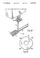
- FIG. 1 is a side view of an enhanced serrated finned tube which can be used with the present invention
- FIG. 2 is a cross-sectional view taken along line 2--2 of FIG. 1;
- FIG. 3 is a cross-sectional view of a prior art serrated finned tube, similar to the view of the enhanced serrated finned tube shown in FIG. 2;
- FIG. 4 is an enlarged partial view of the enhanced serrated finned tube shown in FIG. 2;
- FIG. 5 is a top plan view of a serrated fin strip as it appears prior to being enhanced
- FIG. 6 is a front elevation of the serrated fin strip shown in FIG. 5;
- FIG. 7 is a front elevation of the serrated fin strip shown in FIG. 6 illustrating a method for enhancing the serrated fin strip
- FIG. 8 is an enlarged top plan view of a single enhanced segment having a long tapered indentation
- FIG. 9 is a cross-sectional view taken along line 9--9 of FIG. 8;
- FIG. 10 is an enlarged top plan view of a prior art segment
- FIG. 11 is a cross-sectional view taken along line 11--11 of FIG. 10;
- FIG. 12 is an enlarged top plan view of a single enhanced segment having a broad flat indentation
- FIG. 13 is a cross-sectional view taken along line 13--13 of FIG. 12;
- FIG. 14 is an enlarged top plan view of a single enhanced segment having a central triangular indentation
- FIG. 15 is a cross-sectional view taken along line 15--15 of FIG. 14;
- FIG. 16 is an enlarged top plan view of a single enhanced segment having a long, double tapered indentation
- FIG. 17 is a cross-sectional view taken along line 17--17 of FIG. 16;
- FIG. 18 is an enlarged top plan view of a single enhanced segment having dotted indentations
- FIG. 19 is a cross-sectional view taken along line 19--19 of FIG. 18;
- FIG. 20 is an enlarged top plan view of segments having a diamond pattern indentation impressed therein;
- FIG. 21 is an enlarged top plan view of segments having a pin point pattern indentation impressed therein;
- FIG. 22 is an enlarged top plan view of segments having a horizontal ribbed pattern indentation impressed therein;
- FIG. 23 is an enlarged top plan view of segments having a pitted pattern indentation impressed therein;
- FIG. 24 is an enlarged top plan view of segments having a diagonal ribbed pattern indentation impressed therein;
- FIG. 25 is an enlarged top plan view of segments having jagged, grooved indentations provided at the distal tip of the fin;
- FIG. 26 is a top plan view of a unserrated enhanced fin strip with undulations impressed therein;
- FIG. 27 is a front elevation of the unserrated enhanced fin strip illustrated in FIG. 26;
- FIG. 28 is a front elevation of the unserrated enhanced fin strip of FIG. 27 as it appears after being serrated.
- FIG. 29 is an end view of a finned tube with fins having three zones to accommodate heat transfer for three substantially different fluid flow conditions (indentation patterns are not shown).
- FIG. 30 is an enlarged top plan view of segments having a vertical ribbed pattern indentation impressed therein.
- FIG. 31 is an end view of a fin embossed with a pattern to improve gas flow.
- FIG. 32 is a sketch of a commercial finning process accompanied by a fin material embossing machine suitable for producing the finned tube illustrated in FIG. 29.
- FIG. 33 is an end view of an embossing roll of the present invention having flat spots thereon.
- the present invention includes a finned tube 10 which is comprised of a central hollow tube 12 with a fin 14 attached thereto, usually by welding and preferably by high frequency resistance welding.
- the fin 14 extends outwardly from and is within 15 degrees of the perpendicular with the tube 12.
- the fin 14 is also wrapped helically around the tube 12 with adjacent spirals of the fin 14 spaced apart from each other.
- the fin 14 may be constructed of carbon steel, nickel alloys or other suitable material.
- the fins 14 on the tube 12 are configured to accommodate three substantially different flow conditions encountered by the finned tube 10.
- a first zone generally designated 90 is subjected to fluid flowing radially toward the finned tube 10 from the direction generally designated 91, or the upstream condition.
- a second zone generally designated 92, 92 is subjected to fluid flowing past the tube 12, or the sidestream condition and is both on the top and bottom sides of the tube 12 as it appears in FIG. 29.
- a third zone, generally designated 94 is subjected to fluid flowing radially away from the finned tube 10, or the downstream condition.
- Each flow condition is substantially different from the others, as will be more fully explained below.
- a fin 14 is configured differently at the above-defined zones 90, 92 and 94 to enhance heat transfer at the flow condition encountered at each zone.
- fluid flow at zone 90 i.e., the upstream condition
- a fin 14 in zone 90 may comprise a serrated portion 18; and the segments 24 of the serrated portion 18 can be provided with additional surface or texturization to increase heat transfer.
- the diamond pattern indentations 64, pin point pattern indentations 66, horizontal ribbed pattern indentations 68, pitted pattern indentations 70, and diagonal ribbed pattern indentations 72, as illustrated in FIGS. 20-24 are desirable.
- the base portion 16 of the fin 14 at zone 90 experiences a high pressure and is texturized by toughening to improve heat transfer.
- Fluid flow at zone 92 is generally in transition from substantially laminar to substantially turbulent flow.
- a fin in zone 92 is desirably a plain spiral (non-serrated) fin to improve gas flow.
- Fluid flow at zone 94 is generally turbulent and is at a low pressure relative to flow at zones 90 and 92.
- a fin 14 at zone 94 desirably comprises a serrated portion 18 with segments 24 embossed with a pattern such as vertical ribs which improve gas flow and reduce the pressure drop across the finned tube 10.
- the top and bottom surfaces 32 and 34 of the segments 24 are impressed, respectively, with vertical pattern indentations 96, extending from the proximal area 28 of the segment 24 to the distal tip 30.
- a non-serrated fin 14', embossed with a pattern 98 illustrated in FIG. 31 is utilized to improve gas flow, i.e., lower pressure drop, across a finned tube 10.
- a non-circular fin (not illustrated) is utilized.
- FIGS. 1 through 28 disclose various enhanced serrated tubes; whereas the present invention is not directed to serrated finned tubes which is the claimed invention of the above-mentioned co-pending application, their inclusion herein is for the main purpose of illustrating the types of enhancements available for the present invention in the three different zones thereof. It should be understood that the three zones of the present invention are preferably provided with mutually different enhancements (or lack thereof). Thus, the different enhancements of FIGS. 1 to 28 are discussed as follows:
- an enhanced serrated finned tube 10 is provided with a central hollow tube 12 with a fin 14 attached thereto, usually by welding and preferably by high frequency resistance welding.
- the fin 14 extends outwardly from and is within 15 degrees of perpendicular with the tube 12.
- the fin 14 is also wrapped helically around the tube 12 with adjacent spirals of the fin 14 spaced apart from each other.
- the fin 14 may be constructed of carbon steel, nickel alloys or other suitable material.
- the fin 14 has a base portion 16 located adjacent to the tube 12 and a serrated portion 18 located adjacent to the base portion 16 and extending away from the tube 12.
- the base portion 16 is provided with a proximal edge 20 and an opposite distal area 22.
- the proximal edge 20 attaches to the tube 12 to secure the fin 14 thereto.
- the serrated portion 18 is provided with a multiplicity of segments 24, with adjacent segments 24 separated by gaps 26.
- Each segment 24 is provided with a proximal area 28 which is attached to the distal area 22 of the base portion 16, and with a distal tip 30 located opposite the proximal area 28.
- each segment 24 has a top surface 32 and a bottom surface 34 opposite the top surface 32, and two sides 36 located adjacent to the gaps 26 and on either side of the top and bottom surfaces 32 and 34.
- Each segment 24 has a segment height 38 measured on the segment 24 from the proximal area 28 to the distal tip 30.
- the fin 14 has a fin height 40 measured from the proximal edge 20 of the base portion 16 to the distal tip 30 of the segments 24.
- each segment 24 has at least one segment depth 42; each segment depth 42 is measured from a point 44 on the top surface 32 of the segment 24, through the segment 24, i.e. from the top surface 32 to the bottom surface 34, perpendicularly to the segment height 38.
- the segment depth 42 can vary depending upon which point 44 was selected for measuring the segment depth 42.
- certain embodiments of the enhanced serrated finned tube 10 have segments 24 with top surfaces 32 and bottom surfaces 34 which are not parallel.
- the base portion 16 has at least one base portion depth 46; each base portion depth 46 is measured from a spot 48 on the base portion 16, through the base portion 16 perpendicularly to the fin height 40.
- each segment 24 also has a proximal width 50 measured between the two sides 36 at the proximal area 28 of the segment 24 and a distal width 52 measured between the two sides 36 at the distal tip 30 of the segment 24.
- FIGS. 2, 3, 4, 8, 9 and 10 differences are illustrated between the enhanced serrated finned tube 10 and a prior art serrated fin tube, generally designated by numeral 10'.
- the prior art serrated finned tube 10' is provided with all of the same features as previously described for the enhanced serrated finned tube 10; said features will be hereinafter referred to by designating the numeral of the same feature on the enhanced serrated finned tube 10, followed by a prime '/' symbol.
- 12' is a central hollow tube provided on the prior art serrated finned tube 10' which corresponds with the central hollow tube 12 on the enhanced serrated finned tube 10.
- the segments 24' of the prior art finned tube 10' have two sides 36' which are parallel with each other, and therefore, the segments 24' have distal widths 52' and proximal widths 50' which are equal to each other. This differs from the segments 24 of the enhanced serrated finned tube 10 which has distal widths 52 greater than its proximal widths 50. Widths 50 and 52 are not equal because the segments 24 have been enhanced and thus broadened.
- Enhancing the segments 24 also produces a second difference in the enhanced serrated finned tube 10 with respect to the prior art serrated finned tube 10'.
- the second difference relates to the top and bottom surfaces 32 and 34 of the enhanced serrated finned 10 as compared to the top and bottom surfaces 32' and 34 ⁇ of the prior art serrated finned tube 10'.
- FIG. 11 there is shown a cross-sectional view through the segment 24' of the prior art fin 14'.
- the top and bottom surfaces 32' and 34' are parallel with each other and the segment depth 42' is the same regardless of which point 44' on the top surface 32' is chosen.
- the same is not true for the enhanced serrated fin 14 of the enhanced serrated finned tube 10.
- the segment depth 42 and an alternate segment depth 42A are not the same.
- the fin 14 of the enhanced serrated finned tube 10 shown in FIGS. 8 and 9 is provided with a long, tapered indentation 54 impressed into both the top and bottom surfaces 32 and 34.
- the segments 24 are thus broadened and their surface area is increased.
- Many patterns and designs are possible as indentations 54. A few possible embodiments are illustrated and discussed below.
- FIGS. 12 and 13 illustrate another embodiment wherein a broad flat indentation 56 is impressed into both the top and bottom surfaces 32 and 34 at the distal tip 30 of the segment 24.
- FIGS. 14 and 15 illustrate another embodiment wherein a central triangular indentation 58 is impressed into both the top and bottom surfaces 32 and 34.
- FIGS. 16 and 17 illustrate an additional embodiment wherein a long, double tapered indentation 60 is impressed into both the top and bottom surfaces 32 and 34.
- FIGS. 18 and 19 illustrate another embodiment wherein dotted indentations 62 are impressed into both the top and bottom surfaces 32 and 34.
- FIGS. 20, 21, 22, 23, and 24 illustrate still other embodiments wherein the top and bottom surfaces 32 and 34 are impressed, respectively, with diamond pattern indentations 64, pin point pattern indentations 66, horizontal ribbed pattern indentations 68, pitted pattern indentations 70, and diagonal ribbed pattern indentations 72.
- FIG. 25 illustrates another embodiment wherein the distal tips 30 of the segments 24 are impressed with jagged, grooved indentations 74.
- the following percentages of surface area enhancement are attained utilizing a 2 inch tube 12, various fin heights 40, a base portion depth 46 of 18 gauge metal, a 0.172 inch proximal width 50, and various distal widths 52.
- the data listed below is attained for pie serrated fins 14 which are spaced five (5) fins 14 per inch of tube 12.
- FIGS. 5, 6 and 7 there is illustrated one method for producing the fin 14, i.e. enhancing after serrating and prior to the fin 14 being attached to the tube 12.
- FIGS. 5 and 6 illustrate a straight piece of unenhanced serrated fin strip 76.
- the base portion depth 46 and the segment depths 42 are all equal to each other.
- FIG. 7 shows how the unenhanced serrated fin strip 76 passes between enhancing tools 78 and 80 and emerges as enhanced serrated fin 14 which is ready to be attached to the tube 12 to form the enhanced serrated finned tube 10.
- the base portion 16 is not enhanced, the base portion depth 46 will remain unaltered after enhancement.
- the segments 24 are enhanced, their segment depths 42 and 42A will differ from the base portion depth 46 and possibly differ from each other, depending on which points 44 or 44A are selected.
- FIGS. 26, 27 and 28 show a straight piece of unserrated enhanced fin strip 82.
- FIG. 28 shows the same strip 82 after being serrated to form enhanced serrated fin 14 which is ready to be attached to the tube 12 to form the enhanced serrated finned tube 10.
- the fin enhancements can be added to the fins during a commercial firming process generally designated 100, as shown in FIG. 32.
- the finning process 100 is accompanied by a texturizing or fin material embossing machine 102.
- a commercial finning process 100 comprises helically wrapping a strip or fin 14 around and at an angle to a tube 12 and attaching the strip 14 to the tube 12, preferably by high frequency welding, to form the fins 14 thereon.
- the embossing machine 102 which comprises two embossing rolls 104, is electrically or mechanically linked to the tube 12.
- the rotation rates of the tube 12 and embossing rolls 104 are related by a ratio of whole numbers so that a pattern is repeated each resolution of the tube 12. For example, the tube 12 is rotated at a rate of 600 r.p.m. while the embossing rolls 104 are rotated at a rate of 300 r.p.m., a ratio of 2:1.
- the tolerance in the whole number ratio is adjusted by flat spots 106 on the embossing rolls 104.
- the flat spots 106 allow slippage to adjust for minimal variations in the tube 12 rotation rate due to tooling diameter wear or the effect of metal changes impacting the fin material neutral axis.
- FIG. 33 illustrates a specific embodiment of an embossing roll 104 having four substantially equally spaced apart flat spots 106 thereon. The aforementioned specific embodiment is provided as an example and is not intended to be limiting.
- the number of and spacing between flat spots 106 on an embossing roll 104 are based on strip material of composition and other engineering design considerations.
Abstract
Description
______________________________________
            Distal Width
                       Surface Area Increase
Fin Height  of Segments
                       (In Percentage)
______________________________________
1 inch      0.256 inches
                       13.9
7/8 inch    0.237 inches
                       10.2
3/4 inch    0.218 inches
                       6.7
______________________________________
Claims (7)
Priority Applications (1)
| Application Number | Priority Date | Filing Date | Title |
|---|---|---|---|
| US08/034,471 US5337807A (en) | 1992-08-10 | 1993-03-19 | Flow dependent finned tube |
Applications Claiming Priority (2)
| Application Number | Priority Date | Filing Date | Title |
|---|---|---|---|
| US07/927,015 US5240070A (en) | 1992-08-10 | 1992-08-10 | Enhanced serrated fin for finned tube |
| US08/034,471 US5337807A (en) | 1992-08-10 | 1993-03-19 | Flow dependent finned tube |
Related Parent Applications (1)
| Application Number | Title | Priority Date | Filing Date |
|---|---|---|---|
| US07/927,015 Continuation-In-Part US5240070A (en) | 1992-08-10 | 1992-08-10 | Enhanced serrated fin for finned tube |
Publications (1)
| Publication Number | Publication Date |
|---|---|
| US5337807A true US5337807A (en) | 1994-08-16 |
Family
ID=25454036
Family Applications (2)
| Application Number | Title | Priority Date | Filing Date |
|---|---|---|---|
| US07/927,015 Expired - Fee Related US5240070A (en) | 1992-08-10 | 1992-08-10 | Enhanced serrated fin for finned tube |
| US08/034,471 Expired - Fee Related US5337807A (en) | 1992-08-10 | 1993-03-19 | Flow dependent finned tube |
Family Applications Before (1)
| Application Number | Title | Priority Date | Filing Date |
|---|---|---|---|
| US07/927,015 Expired - Fee Related US5240070A (en) | 1992-08-10 | 1992-08-10 | Enhanced serrated fin for finned tube |
Country Status (14)
| Country | Link |
|---|---|
| US (2) | US5240070A (en) |
| EP (1) | EP0653044A4 (en) |
| JP (1) | JPH07509774A (en) |
| KR (1) | KR950702303A (en) |
| AU (1) | AU668768B2 (en) |
| BR (1) | BR9306862A (en) |
| CA (1) | CA2142201A1 (en) |
| DE (1) | DE653044T1 (en) |
| ES (1) | ES2075823T1 (en) |
| FI (1) | FI950544A0 (en) |
| MY (1) | MY109545A (en) |
| RU (1) | RU95106774A (en) |
| TW (1) | TW229264B (en) |
| WO (1) | WO1994003766A1 (en) |
Cited By (11)
| Publication number | Priority date | Publication date | Assignee | Title |
|---|---|---|---|---|
| US5857515A (en) * | 1995-04-12 | 1999-01-12 | David M. Skupien | Heat exchanging device |
| EP0947793A2 (en) | 1998-03-31 | 1999-10-06 | ABB Combustion Engineering S.p.A. | Finned-tube heat exchanger |
| US20090229806A1 (en) * | 2008-03-12 | 2009-09-17 | Jiangsu Cuilong Copper Industry Co., Ltd. | Enhanced Heat Transfer Tube and Manufacture Method Thereof |
| CN101655035A (en) * | 2008-08-19 | 2010-02-24 | 通用电气公司 | Dimpled serrated fin tube structure |
| US20100155041A1 (en) * | 2008-12-19 | 2010-06-24 | Gea Batignolles Technologies Thermiques | Heat exchanger comprising tubes with grooved fins |
| US20100186443A1 (en) * | 2009-01-23 | 2010-07-29 | General Electric Company | Heat transfer tubes |
| US20100282456A1 (en) * | 2009-05-06 | 2010-11-11 | General Electric Company | Finned tube heat exchanger |
| DE102009030824A1 (en) | 2009-06-26 | 2010-12-30 | Behr Gmbh & Co. Kg | Heat exchanger, particularly coolant cooler for motor vehicles, has tubes, ribs and collecting tank communicating with tubes, where tubes are formed as single ribbed tubes |
| US20140131010A1 (en) * | 2012-11-12 | 2014-05-15 | Exxonmobil Research And Engineering Company | Condensing air preheater with heat pipes |
| US9958215B2 (en) | 2013-03-15 | 2018-05-01 | Dana Canada Corporation | Heat transfer surface with nested tabs |
| US11029095B2 (en) * | 2015-07-30 | 2021-06-08 | Senior Uk Limited | Finned coaxial cooler |
Families Citing this family (30)
| Publication number | Priority date | Publication date | Assignee | Title |
|---|---|---|---|---|
| DE69419121T2 (en) * | 1993-07-21 | 1999-10-14 | Babcock Hitachi Kk | HEAT EXCHANGER WITH FIN TUBES |
| DE4404357C2 (en) * | 1994-02-11 | 1998-05-20 | Wieland Werke Ag | Heat exchange tube for condensing steam |
| IL118159A0 (en) * | 1996-05-06 | 1996-12-05 | Israel State | Improved heat exchangers |
| JPH10206059A (en) * | 1997-01-20 | 1998-08-07 | Toshiba Corp | Heat exchanger |
| US6009936A (en) * | 1997-04-17 | 2000-01-04 | Sanyo Electric Co., Ltd. | Heat exchanger |
| US6234245B1 (en) | 1998-07-02 | 2001-05-22 | Fintube Technologies, Inc. | Aero curve fin segment |
| US6626134B1 (en) * | 1999-07-27 | 2003-09-30 | Keith A. Brinton | Engine cooling system and method for making same |
| JP2003515096A (en) * | 1999-11-22 | 2003-04-22 | フィンチューブ テクノロジーズ インコーポレイテッド | Aerodynamically curved fin segments |
| DE10063831A1 (en) * | 2000-12-21 | 2002-07-11 | Bruendermann Georg | Serrated rib and heat exchanger tube provided with it |
| US20030213441A1 (en) * | 2002-06-03 | 2003-11-20 | Brinton Keith A. | Engine cooling system and method for making same |
| FR2900723B1 (en) * | 2006-05-02 | 2008-08-22 | Peugeot Citroen Automobiles Sa | EVAPORATOR / ABSORBER ASSEMBLY, ABSORPTION COOLING DEVICE AND MOTOR VEHICLE THEREFOR. |
| US8021109B2 (en) * | 2008-01-22 | 2011-09-20 | General Electric Company | Turbine casing with false flange |
| US8210802B2 (en) * | 2008-01-22 | 2012-07-03 | General Electric Company | Turbine casing |
| TWI385344B (en) * | 2009-10-20 | 2013-02-11 | Foxsemicon Integrated Tech Inc | Led illumination device |
| CN101782344B (en) * | 2010-02-03 | 2012-09-05 | 上海化工研究院 | Heat exchange tube with two reinforced surfaces |
| WO2011141800A1 (en) | 2010-05-10 | 2011-11-17 | Endosense S.A. | Irrigated finned ablation head |
| EP2780650B1 (en) * | 2011-11-18 | 2019-01-23 | Carrier Corporation | Shell and tube heat exchanger |
| KR101173842B1 (en) * | 2012-05-21 | 2012-08-16 | 주식회사 한국번디 | L type turn-fin tube and turn-fin type heat exchanger using the l type turn-fin tube |
| US9086174B2 (en) | 2013-03-15 | 2015-07-21 | Securus, Inc. | Extendable sleeve for poured concrete deck |
| JP2015021650A (en) * | 2013-07-17 | 2015-02-02 | 三菱重工業株式会社 | Heat transfer tube structure |
| JP6189120B2 (en) * | 2013-07-17 | 2017-08-30 | 三菱日立パワーシステムズ株式会社 | Heat transfer tube structure |
| CN104048543A (en) * | 2014-06-25 | 2014-09-17 | 上海理工大学 | Flat-tooth longitudinal finned tube |
| CN104048544A (en) * | 2014-06-25 | 2014-09-17 | 上海理工大学 | Twisted-tooth longitudinal finned tube |
| CN104053342A (en) * | 2014-06-25 | 2014-09-17 | 上海理工大学 | Twisted-tooth cooling fin |
| CN104110989A (en) * | 2014-06-25 | 2014-10-22 | 上海理工大学 | H-shaped flat tooth finned tube and H-shaped flat tooth finned tube heat exchange tube bundle |
| CN104075606A (en) * | 2014-06-25 | 2014-10-01 | 上海理工大学 | Twisted tooth fin oblate heat exchange tube |
| US10436524B2 (en) * | 2014-07-03 | 2019-10-08 | King Mongkut's University Of Technology Thonburi | Mixed louver spiral fin |
| CA2930827A1 (en) * | 2016-05-25 | 2017-11-25 | Nova Chemicals Corporation | Furnace coil modified fins |
| WO2018044319A1 (en) * | 2016-09-02 | 2018-03-08 | General Electric Company | Finned tube heat exchanger with enhanced serrated fins and method of assembling same |
| US10975567B2 (en) * | 2017-12-21 | 2021-04-13 | Reliance Worldwide Corporation | Extendable sleeve for poured concrete deck |
Citations (4)
| Publication number | Priority date | Publication date | Assignee | Title |
|---|---|---|---|---|
| US2122504A (en) * | 1936-05-02 | 1938-07-05 | Wilson Lee | Heating apparatus |
| US4538677A (en) * | 1982-04-06 | 1985-09-03 | Energiagazdalkodasi Intezet | Helicoidally finned tubes |
| US4763726A (en) * | 1984-08-16 | 1988-08-16 | Sunstrand Heat Transfer, Inc. | Heat exchanger core and heat exchanger employing the same |
| US5031694A (en) * | 1988-07-08 | 1991-07-16 | H.E.T. Limited | Heat exchange device and method of manufacture therefor |
Family Cites Families (15)
| Publication number | Priority date | Publication date | Assignee | Title |
|---|---|---|---|---|
| CH235639A (en) * | 1942-05-04 | 1944-12-15 | Bbc Brown Boveri & Cie | Finned tube for heat exchangers with sheet metal fins arranged in a radial pattern and method for producing the same. |
| DE1062352B (en) * | 1957-09-27 | |||
| GB906282A (en) * | 1960-10-27 | 1962-09-19 | Birwelco Ltd | Improvements in and relating to heat exchangers |
| GB944108A (en) * | 1960-11-24 | 1963-12-11 | Babcock & Wilcox Ltd | Improvements in finned tubes and heat exchangers formed of such tubes |
| FR1546808A (en) * | 1967-10-13 | 1968-11-22 | Method of making a heat exchange tube, heat exchange tube and heat exchanger by making application | |
| FR1604823A (en) * | 1967-12-01 | 1972-04-17 | ||
| US3519070A (en) * | 1968-06-14 | 1970-07-07 | Coolenheat Inc | Heat exchange unit |
| SU507767A1 (en) * | 1974-02-13 | 1976-03-25 | Heat exchanger tube | |
| US4227572A (en) * | 1978-03-27 | 1980-10-14 | Seton-Scherr, Inc. | Finned tubing |
| US4258782A (en) * | 1979-06-28 | 1981-03-31 | Modine Manufacturing Company | Heat exchanger having liquid turbulator |
| JPS56130598A (en) * | 1980-03-17 | 1981-10-13 | Mitsubishi Heavy Ind Ltd | Heat exchanger |
| FR2568000A1 (en) * | 1984-07-19 | 1986-01-24 | Stein Industrie | FINED EXCHANGER TUBE |
| NL8403278A (en) * | 1984-10-30 | 1986-05-16 | Philips Nv | HEAT EXCHANGER WITH FINED PIPE. |
| JPS611995A (en) * | 1985-05-29 | 1986-01-07 | Hitachi Ltd | Spiral fin |
| SE8803215D0 (en) * | 1988-09-13 | 1988-09-13 | Gadelius Sunrod Ab | Surface Magnifier for VERMEVEXLARTUB |
-
1992
- 1992-08-10 US US07/927,015 patent/US5240070A/en not_active Expired - Fee Related
-
1993
- 1993-03-19 US US08/034,471 patent/US5337807A/en not_active Expired - Fee Related
- 1993-07-15 DE DE0653044T patent/DE653044T1/en active Pending
- 1993-07-15 EP EP93919821A patent/EP0653044A4/en not_active Ceased
- 1993-07-15 RU RU95106774/06A patent/RU95106774A/en unknown
- 1993-07-15 BR BR9306862A patent/BR9306862A/en not_active Application Discontinuation
- 1993-07-15 CA CA002142201A patent/CA2142201A1/en not_active Abandoned
- 1993-07-15 AU AU49925/93A patent/AU668768B2/en not_active Ceased
- 1993-07-15 ES ES93919821T patent/ES2075823T1/en active Pending
- 1993-07-15 JP JP6505317A patent/JPH07509774A/en active Pending
- 1993-07-15 WO PCT/US1993/006553 patent/WO1994003766A1/en not_active Application Discontinuation
- 1993-07-27 TW TW082105955A patent/TW229264B/zh active
- 1993-08-09 MY MYPI93001577A patent/MY109545A/en unknown
-
1994
- 1994-12-28 KR KR1019940704780A patent/KR950702303A/en not_active Application Discontinuation
-
1995
- 1995-02-08 FI FI950544A patent/FI950544A0/en not_active Application Discontinuation
Patent Citations (4)
| Publication number | Priority date | Publication date | Assignee | Title |
|---|---|---|---|---|
| US2122504A (en) * | 1936-05-02 | 1938-07-05 | Wilson Lee | Heating apparatus |
| US4538677A (en) * | 1982-04-06 | 1985-09-03 | Energiagazdalkodasi Intezet | Helicoidally finned tubes |
| US4763726A (en) * | 1984-08-16 | 1988-08-16 | Sunstrand Heat Transfer, Inc. | Heat exchanger core and heat exchanger employing the same |
| US5031694A (en) * | 1988-07-08 | 1991-07-16 | H.E.T. Limited | Heat exchange device and method of manufacture therefor |
Cited By (18)
| Publication number | Priority date | Publication date | Assignee | Title |
|---|---|---|---|---|
| US5857515A (en) * | 1995-04-12 | 1999-01-12 | David M. Skupien | Heat exchanging device |
| EP0947793A2 (en) | 1998-03-31 | 1999-10-06 | ABB Combustion Engineering S.p.A. | Finned-tube heat exchanger |
| EP0947793A3 (en) * | 1998-03-31 | 2000-08-09 | ABB Combustion Engineering S.p.A. | Finned-tube heat exchanger |
| US20090229806A1 (en) * | 2008-03-12 | 2009-09-17 | Jiangsu Cuilong Copper Industry Co., Ltd. | Enhanced Heat Transfer Tube and Manufacture Method Thereof |
| US8091616B2 (en) * | 2008-03-12 | 2012-01-10 | Jiangsu Cuilong Precision Copper Tube Corporation | Enhanced heat transfer tube and manufacture method thereof |
| CN101655035A (en) * | 2008-08-19 | 2010-02-24 | 通用电气公司 | Dimpled serrated fin tube structure |
| US20100043442A1 (en) * | 2008-08-19 | 2010-02-25 | General Electric Company | Dimpled serrated fintube structure |
| US20100155041A1 (en) * | 2008-12-19 | 2010-06-24 | Gea Batignolles Technologies Thermiques | Heat exchanger comprising tubes with grooved fins |
| US8376033B2 (en) * | 2008-12-19 | 2013-02-19 | Gea Batignolles Technologies Thermiques | Heat exchanger comprising tubes with grooved fins |
| US8281564B2 (en) * | 2009-01-23 | 2012-10-09 | General Electric Company | Heat transfer tubes having dimples arranged between adjacent fins |
| US20100186443A1 (en) * | 2009-01-23 | 2010-07-29 | General Electric Company | Heat transfer tubes |
| CN101915412A (en) * | 2009-01-23 | 2010-12-15 | 通用电气公司 | Heat-transfer pipe |
| US20100282456A1 (en) * | 2009-05-06 | 2010-11-11 | General Electric Company | Finned tube heat exchanger |
| US20120111552A1 (en) * | 2009-05-06 | 2012-05-10 | General Electric Company | Finned tube heat exchanger |
| DE102009030824A1 (en) | 2009-06-26 | 2010-12-30 | Behr Gmbh & Co. Kg | Heat exchanger, particularly coolant cooler for motor vehicles, has tubes, ribs and collecting tank communicating with tubes, where tubes are formed as single ribbed tubes |
| US20140131010A1 (en) * | 2012-11-12 | 2014-05-15 | Exxonmobil Research And Engineering Company | Condensing air preheater with heat pipes |
| US9958215B2 (en) | 2013-03-15 | 2018-05-01 | Dana Canada Corporation | Heat transfer surface with nested tabs |
| US11029095B2 (en) * | 2015-07-30 | 2021-06-08 | Senior Uk Limited | Finned coaxial cooler |
Also Published As
| Publication number | Publication date |
|---|---|
| ES2075823T1 (en) | 1995-10-16 |
| KR950702303A (en) | 1995-06-19 |
| EP0653044A1 (en) | 1995-05-17 |
| TW229264B (en) | 1994-09-01 |
| WO1994003766A1 (en) | 1994-02-17 |
| DE653044T1 (en) | 1995-11-09 |
| AU668768B2 (en) | 1996-05-16 |
| EP0653044A4 (en) | 1995-10-04 |
| MY109545A (en) | 1997-02-28 |
| AU4992593A (en) | 1994-03-03 |
| FI950544A (en) | 1995-02-08 |
| JPH07509774A (en) | 1995-10-26 |
| CA2142201A1 (en) | 1994-02-17 |
| US5240070A (en) | 1993-08-31 |
| FI950544A0 (en) | 1995-02-08 |
| RU95106774A (en) | 1996-12-27 |
| BR9306862A (en) | 1998-12-08 |
Similar Documents
| Publication | Publication Date | Title |
|---|---|---|
| US5337807A (en) | Flow dependent finned tube | |
| US4794775A (en) | Method of producing a heat transfer tube for single-phase flow | |
| US5682946A (en) | Tube for use in a heat exchanger | |
| JP4065785B2 (en) | Improved heat transfer tube with grooved inner surface | |
| US6378605B1 (en) | Heat exchanger with transpired, highly porous fins | |
| US20010006106A1 (en) | Heat-exchanger tube structured on both side and a method for its manufacture | |
| US6631758B2 (en) | Internally finned heat transfer tube with staggered fins of varying height | |
| US6067712A (en) | Heat exchange tube with embossed enhancement | |
| US20050241150A1 (en) | Method of manufacture of heat-exchanger tube structured on both sides | |
| US6298909B1 (en) | Heat exchange tube having a grooved inner surface | |
| US6167950B1 (en) | Heat transfer tube | |
| US5377746A (en) | Texturized fin | |
| US20030173071A1 (en) | Reversible grooved tubes for heat exchangers | |
| US7418848B2 (en) | High-performance and high-efficiency rolled fin tube and forming disk therefor | |
| JPH07253287A (en) | Heat exchanger tube having internal element | |
| US1979859A (en) | Tube for boilers, heat exchangers, and the like | |
| JPS6029594A (en) | Heat-transmitting pipe and manufacture thereof | |
| JPH11325754A (en) | Heat-exchanger and u-shaped pipe for heat-exchanger | |
| JP4632487B2 (en) | Internal grooved heat transfer tube and manufacturing method thereof | |
| GB2043867A (en) | Heat Transfer Tube and Method of Making Same | |
| CA2330084C (en) | Heat exchanger with transpired, highly porous fins | |
| JP4020678B2 (en) | Internal grooved heat transfer tube and manufacturing method thereof | |
| JP2922824B2 (en) | Heat transfer tube with internal groove | |
| CN112524987A (en) | Reinforced heat exchange tube with ribs on inner surface and manufacturing method thereof | |
| JPH10263603A (en) | Rolling method for forming groove on surface of metallic plate |
Legal Events
| Date | Code | Title | Description |
|---|---|---|---|
| FPAY | Fee payment |
Year of fee payment: 4 |
|
| SULP | Surcharge for late payment | ||
| AS | Assignment |
Owner name: FINTUBE TECHNOLOGIES, INC., TEXAS Free format text: ASSIGNMENT OF ASSIGNORS INTEREST;ASSIGNOR:FINTUBE LIMITED PARTNERSHIP;REEL/FRAME:010572/0523 Effective date: 20000103 |
|
| AS | Assignment |
Owner name: BANK OF AMERICA, N.A., OKLAHOMA Free format text: SECURITY INTEREST;ASSIGNOR:FINTUBE TECHNOLOGIES, INC.;REEL/FRAME:010567/0063 Effective date: 20000103 |
|
| FEPP | Fee payment procedure |
Free format text: PAT HOLDER NO LONGER CLAIMS SMALL ENTITY STATUS, ENTITY STATUS SET TO UNDISCOUNTED (ORIGINAL EVENT CODE: STOL); ENTITY STATUS OF PATENT OWNER: LARGE ENTITY |
|
| REFU | Refund |
Free format text: REFUND - PAYMENT OF MAINTENANCE FEE, 8TH YR, SMALL ENTITY (ORIGINAL EVENT CODE: R284); ENTITY STATUS OF PATENT OWNER: LARGE ENTITY |
|
| FPAY | Fee payment |
Year of fee payment: 8 |
|
| AS | Assignment |
Owner name: CIT GROUP/BUSINESS CREDIT, INC., THE, TEXAS Free format text: SECURITY INTEREST;ASSIGNOR:FINTUBE TECHNOLOGIES, INC.;REEL/FRAME:013862/0952 Effective date: 20011008 Owner name: FINTUBE TECHNOLOGIES, INC., TEXAS Free format text: ASSIGNMENT OF ASSIGNORS INTEREST;ASSIGNOR:BANK OF AMERICA, N.A.;REEL/FRAME:013868/0151 Effective date: 20011115 |
|
| REMI | Maintenance fee reminder mailed | ||
| LAPS | Lapse for failure to pay maintenance fees | ||
| LAPS | Lapse for failure to pay maintenance fees |
Free format text: PATENT EXPIRED FOR FAILURE TO PAY MAINTENANCE FEES (ORIGINAL EVENT CODE: EXP.); ENTITY STATUS OF PATENT OWNER: LARGE ENTITY |
|
| STCH | Information on status: patent discontinuation |
Free format text: PATENT EXPIRED DUE TO NONPAYMENT OF MAINTENANCE FEES UNDER 37 CFR 1.362 |
|
| FP | Lapsed due to failure to pay maintenance fee |
Effective date: 20060816 |
|
| AS | Assignment |
Owner name: THE CIT GROUP/BUSINESS CREDIT, INC., A NEW YORK CO Free format text: SECURITY AGREEMENT FOR SECOND AMENDED AND RESTATED FINANCING AGREEMENT;ASSIGNOR:FINTUBE TECHNOLOGIES, INC., AN OKLAHOMA CORPORATION;REEL/FRAME:018645/0685 Effective date: 20061214 |
|
| AS | Assignment |
Owner name: FINTUBE TECHNOLOGIES, INC., OKLAHOMA Free format text: RELEASE BY SECURED PARTY;ASSIGNOR:CIT GROUP/BUSINESS CREDIT INC.;REEL/FRAME:019930/0005 Effective date: 20070614 |