US5313402A - Midway start method in numerical control system - Google Patents
Midway start method in numerical control system Download PDFInfo
- Publication number
- US5313402A US5313402A US07/983,757 US98375792A US5313402A US 5313402 A US5313402 A US 5313402A US 98375792 A US98375792 A US 98375792A US 5313402 A US5313402 A US 5313402A
- Authority
- US
- United States
- Prior art keywords
- tool
- block
- machining
- midway
- machining program
- Prior art date
- Legal status (The legal status is an assumption and is not a legal conclusion. Google has not performed a legal analysis and makes no representation as to the accuracy of the status listed.)
- Expired - Fee Related
Links
Images





Classifications
-
- G—PHYSICS
- G05—CONTROLLING; REGULATING
- G05B—CONTROL OR REGULATING SYSTEMS IN GENERAL; FUNCTIONAL ELEMENTS OF SUCH SYSTEMS; MONITORING OR TESTING ARRANGEMENTS FOR SUCH SYSTEMS OR ELEMENTS
- G05B19/00—Program-control systems
- G05B19/02—Program-control systems electric
- G05B19/18—Numerical control [NC], i.e. automatically operating machines, in particular machine tools, e.g. in a manufacturing environment, so as to execute positioning, movement or co-ordinated operations by means of program data in numerical form
- G05B19/182—Numerical control [NC], i.e. automatically operating machines, in particular machine tools, e.g. in a manufacturing environment, so as to execute positioning, movement or co-ordinated operations by means of program data in numerical form characterised by the machine tool function, e.g. thread cutting, cam making, tool direction control
-
- G—PHYSICS
- G05—CONTROLLING; REGULATING
- G05B—CONTROL OR REGULATING SYSTEMS IN GENERAL; FUNCTIONAL ELEMENTS OF SUCH SYSTEMS; MONITORING OR TESTING ARRANGEMENTS FOR SUCH SYSTEMS OR ELEMENTS
- G05B2219/00—Program-control systems
- G05B2219/30—Nc systems
- G05B2219/36—Nc in input of data, input key till input tape
- G05B2219/36074—Display part, select, mark element and edit corresponding block
-
- G—PHYSICS
- G05—CONTROLLING; REGULATING
- G05B—CONTROL OR REGULATING SYSTEMS IN GENERAL; FUNCTIONAL ELEMENTS OF SUCH SYSTEMS; MONITORING OR TESTING ARRANGEMENTS FOR SUCH SYSTEMS OR ELEMENTS
- G05B2219/00—Program-control systems
- G05B2219/30—Nc systems
- G05B2219/50—Machine tool, machine tool null till machine tool work handling
- G05B2219/50087—Rough, coarse and finish, fine machining
-
- G—PHYSICS
- G05—CONTROLLING; REGULATING
- G05B—CONTROL OR REGULATING SYSTEMS IN GENERAL; FUNCTIONAL ELEMENTS OF SUCH SYSTEMS; MONITORING OR TESTING ARRANGEMENTS FOR SUCH SYSTEMS OR ELEMENTS
- G05B2219/00—Program-control systems
- G05B2219/30—Nc systems
- G05B2219/50—Machine tool, machine tool null till machine tool work handling
- G05B2219/50101—For fine machining, select tool and offset, block and restart midway
Definitions
- This invention relates to a method for midway starting a machining program in a numerical control (NC) system, and more particularly, relates to a method for starting the machining process in a unit of a step in the numerical control system.
- NC numerical control
- the first machining is conducted for a work by subtracting or adding a predetermined value from or to a preset tool offset value.
- the work which has been cut by the first machining process is of the size of a product plus a constant finishing stock.
- a machining program generally comprises of programs for each machining step which are arranged in the order of the machining. If it is assumed that the machining program for each machining step is a step program, and each block of the machining program is expressed as follows, then the machining program comprising five machining steps is regarded as step programs with blocks of BLK (n1), BLK (n2), BLK (n3), BLK (n4) and BLK (n5) arranged at the top of each step in the sequence of the machining order.
- BLK (n) n means the number of blocks counted from the top block in the machining program.
- the top block of each step program is a block designating a tool in which a tool change command 80 is written. Therefore, the top block of each step program becomes as follows;
- BLK (n5) the tool command block for the fifth machining step.
- the blocks included in the machining step become as follows;
- the first machining step BLK (n1) to BLK (n2-1)
- the second machining step BLK (n2) to BLK (n3-1)
- the third machining step BLK (n3) to BLK (n4-1)
- the fourth machining step BLK (n4) to BLK (n5-1)
- the fifth machining step BLK (n5) to . . .
- the first machining step roughly cut outer diameter
- the second machining step roughly cut inner diameter
- the third machining step finishing outer diameter
- the fourth machining step finishing inner diameter
- the fifth machining step groove
- the machining for the second time is to start from the third step (or the step for the finishing outer diameter).
- the top block BLK (n3) of the third machining step is designated in the command as the midway starting block to start the machining.
- FIG. 2 shows the display screen which indicates required operations as shown below:
- a machining program 61 is displayed on the display screen 60.
- the machining program If the machining program is executed under such conditions, it will start from the block (the block for midway start) at which the cursor 62 is positioned.
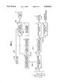
- FIG. 3 is a block diagram to show an embodiment to realize a conventional midway start method. The conventional method will now be described referring to FIG. 3.
- a machining program PRO to be executed is first stored in a machining program memory 4 in the form of a paper tape 1, a floppy disc 2, communication 3 and so on.
- the machining program PRO is read out from the machining program memory 4 and is displayed on a display unit 12 by means of a machining program display section 11. Since the number of blocks which can be displayed on the display unit 12 is limited as shown in FIG. 2, if it is assumed that the blocks BLK (n) through BLK (n+m-1) (wherein m means the number of blocks which can be displayed on the display unit 12) are currently displayed on the display unit 12, and if the key signal CSR sent out from an input unit 9 is a page-up key, the displayed screen is renewed so that the blocks BLK (n+m) through BLK (n+2m-1) will be displayed by means of the machining program display section 11. If the key signal CSR is a page-down key, the display screen will be renewed so that the blocks from BLK (n-m-1) to BLK (n-1) may be displayed on the screen.
- the cursor 62 shown in FIG. 2 is moved correspondingly to the key signal CSR and displayed on the screen.
- the machining program PRO When a machining start command is inputted from an input unit (not shown), the machining program PRO is read in and interpreted in the unit of a block by means of the machining program executing section 5, and a motor control signal DTM and an I/O control signal DTS are respectively sent out to a motor controlling section 6 and an I/O controlling section 8.
- the machining program PRO In a normal machining, the machining program PRO is read in from the top block BLK (1) by means of the machining program executing section 5, but reading-in will start from the midway start block BLK (NCB) if the number NCB of the blocks from the top to the midway start block is sent out from the midway start block instruction section 10.
- NCB midway start block BLK
- a motor 7 comprising a feed shaft motor and a spindle motor or the like is driven by the motor controlling section 6 based on the motor control signal DTM sent out from the machining program executing section 5, and various driving systems are driven by the I/O controlling section 8 based on the I/O control signal DTS sent out from the machining program executing section 5.
- the machining program executing section 5 may interpret the machining program PRO from the top block BLK (1) to a block BLK (NCB-1) which is immediately preceding the midway start block without sending out the motor control signal DTM and the I/O control signal DTS, and send out the motor control signal DTM and the I/O control signal DTS from the midway start block BLK (NCB).
- a machining program comprises the following step programs as shown in FIG. 1;
- the first machining step roughly cut outer diameter
- the second machining step roughly cut inner diameter
- the third machining step finishing outer diameter
- the fourth machining step finishing inner diameter
- the fifth machining step groove
- the machining program is to be started from the third machining step (for the finishing outer diameter)
- an operator must move the page key until the time the top block BLK (n3) of the third machining step is displayed, and further must manipulate the cursor key to move it to the top block BLK (n3) of the third machining step. Since the finishing step is usually positioned in the latter part of the machining program, the number of manipulations that the operator should have with keys such as the page key and the cursor key becomes enormous.
- the conventional method is further defective in that it is extremely difficult to find a top block (or the tool command block related to the tool which is to be used in the machining step from which he/she wishes to start the machining program) of the machining step from which an operator wishes to start the program out of a large number of blocks displayed on the screen. Since such complicated operation becomes necessary every time he/she manipulates the page key, he/she has to bear a heavy burden and trouble.
- This invention was conceived in order to obviate such problems encountered in the prior art and aims at providing a method for starting a machining program midway in a numerical control system which can specify a particular block from which an operator wishes to start the machining program with a smaller number of key manipulations even if the particular block is situated in the latter part of the machining program, and which does not need to find the block out of the large number of blocks which are displayed on the screen.
- a midway start method in a numerical control system wherein a specified block is selected as a midway start block out of the blocks of a machining program to execute the machining program from said selected midway start block, which comprises the steps of extracting a tool command block wherein a tool exchange command is written from said machining program, displaying the tool numbers or tool offset numbers in the unit of said tool command block, selecting a specified tool number or the tool offset number out of said tool numbers or the tool offset numbers, and determining the tool command block wherein said specific tool number or the specific tool offset number is written as said midway start block.
- a midway start method in a numerical control system wherein a specified block is selected as a midway start block out of the blocks of a machining program to execute the machining program from said selected midway start block, which comprises the steps of preparing tool drawing data for each tool number or each tool offset number in advance, extracting a tool command block out of said machining program, displaying tool shapes for each of said tool command blocks based on said tool drawing data corresponding to the tool number or the tool offset number designated in said tool command block, selecting a specific tool shape out of said tool shapes, and determining the tool command block wherein the tool number or the tool offset number corresponding to said specific tool shape is written as the midway start block.
- FIG. 1 is a view to explain the general machining program
- FIG. 2 is a view to show an example of the display screen according to the conventional method
- FIG. 3 is a block diagram to show an embodiment of the numerical control system to realize the midway start method for NC system in the prior art
- FIG. 4 is a block diagram to show the first embodiment of the numerical control system to realize the midway start method according to this invention
- FIG. 5 is a block diagram to show the second embodiment of the numerical control system to realize the midway start method according to this invention.
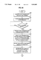
- FIGS. 6A and 6B are flow charts to explain this invention method
- FIG. 7 is a view to show the first example of the display screen of this invention method.
- FIG. 8 is a view to show the second example of the display screen of this invention method.
- FIG. 4 is a block diagram to show the first embodiment to realize the midway start method in a numerical control system in correspondence with FIG. 3.
- the same parts are denoted with the same reference numbers and the explanations thereof are omitted.
- a tool command block TLBLK is extracted out of the machining program PRO stored in the machining program memory 4 by means of a tool command block extracting section 13, and the number TLA of blocks from the top block to the tool command block TLBLK is combined with the tool number TLB at the tool command block TLBLK to be sent to a tool shape display section 14 as well as to a midway start block instruction section 10'. Since the tool command blocks exist in a plural number, if the extracted tool command block TLBLK is the Nth tool command block, the number of the blocks from the top block to the tool command block TLBLK becomes "TLA (N)" and the tool number at the tool command block TLBLK becomes "TLB (N)".
- the number TLA of blocks from the top block to the tool command block TLBLK may easily be generated by setting the block counter used when the tool change command is searched.
- the tool drawing data GRF is read in from a tool drawing data memory 15 based on the tool number TLB at the tool command block TLBLK sent out from the tool command block extracting section 13 and a tool shape TFM is displayed on the display unit 12 based on the tool drawing data GRF.
- the tool drawing data GRF is a drawing data defined by each of the tool numbers for tool shape graphic display, and is registered in advance by an operator in correspondence with each tool attached to the machine.
- the tool drawing data GRF is similar to the drawing data to be used for tool shape display in machining simulation, detailed description on the setting method and data structure thereof will be omitted. Since the tool drawing data GRF is a drawing data defined in the unit of a tool number, if K is assumed to denote a tool number, it would be expressed as follows;
- the tool shape TFM corresponding to the tool command block can be displayed on the screen if it is read in from the tool drawing data memory 15.
- the tool shape display section 14 is displaying on the same screen a cursor which indicates one of the plural tool shapes on the display and moving the cursor correspondingly to the key signal CSR sent out from the input unit 9 having the cursor key and so on. Therefore, an operator can select one tool shape (the shape of a tool to be used in the step he/she wishes to start) out of the plural tool shapes TFM on display simply by manipulating the cursor key.
- the key signal CSR sent from the input unit 9, on the other hand, is also sent out to the midway start block instruction section 10' so that a tool command block (a midway start block) which corresponds to the selected tool shape is specified by the midway start block instruction section 10' based on the key signal CSR.
- the specified midway start block is the Nth tool command block
- the machining program is started midway by the machining start command inputted from the input unit (not shown).
- FIG. 5 is a block diagram to show the second embodiment of the numerical control system which realizes the midway start method according to this invention wherein a machining path display section 16 is newly added.
- the machining program PRO from the midway start block BLK (NCB) to the next tool command block BLK (NCN) is read in one block by one block by the machining program executing section 5 and interpreted, and the motor control signal DTM is sent out to the machining path display section 16.
- the machining path display section 16 generates the machining path drawing data SIM based on the motor control signal DTM sent out from the machining program executing section 5, and the machining paths from the midway start block to the next tool command block are displayed on the display unit 12.
- the machining program PRO is read in and interpreted again one block by one block from the midway start block BLK (NCB) by the machining program executing section 5 and the motor control signal DTM and the I/O control signal DTS are sent out to the motor controlling section 6 and the I/O controlling section 8 respectively to start the machining midway.
- NNB midway start block BLK
- FIGS. 6A and 6B are flow charts to show an example of the midway start method in a numerical control system according to this invention.
- FIGS. 7 and 8 show examples of the display screen of the midway start method according to this invention. Referring to FIGS. 6A, 6B, 7 and 8, the midway start method according to this invention will now be described.
- the machining program PRO stored in the machining program memory 4 comprises five step programs with top blocks of BLK (n1), BLK (n2), BLK (n3), BLK (n4) and BLK (n5) respectively as shown in FIG. 1, and the types of the steps and tool numbers are assumed to be as follows:
- the tool drawing data GRF are registered as follows for each tool number (Step S20);
- GRF (1) a cutter for the outer diameter with tool angle 80°
- GRF (2) a cutter for the inner diameter with tool angle 55°
- GRF (3) a cutter for the outer diameter with tool angle 55°
- GRF (4) a cutter for the inner diameter with tool angle 55°
- GRF (5) a cutter for the groove
- step S20 If they have already been registered for executing the machining simulation, then the above step S20 will not be necessary.
- Step S21 a machining program to be executed should be selected.
- the above step S21 becomes unnecessary.
- the tool command block is extracted from the machining program.
- the number TLA of the blocks from the top block to the tool command block and the tool number TLB at the tool command block are as follows (Steps S22 and S23);
- TLA (1) n1
- TLB (1) 1
- TLA (3) n3
- TLB (3) 3
- a tool drawing data GRF corresponding to the tool number TLB in the tool command block is selected, and a tool shape list table 40 is displayed on the screen 60 as shown in FIG. 7.
- the tool shape list table 40 corresponding to the tool drawing data GRF (TLB (1)) through GRF (TLB (5)), the following will be displayed.
- Tool shape 42 a cutter for the outer diameter with tool angle 80° (the first machining step)
- Tool shape 43 a cutter for the inner diameter with tool angle 55° (the second machining step)
- Tool shape 44 a cutter for the outer diameter with tool angle 55° (the second machining step)
- Tool shape 45 a cutter for the inner diameter with tool angle 55° (the fourth machining step)
- Tool shape 46 a cutter for the groove (the fifth machining step)
- the tool shapes 42 through 46 are attached with serial numbers on the display and a cursor 41 is displayed in a manner to be movable over these numbers (Step S24).
- one tool shape (the tool shape of the machining step from which the program should be started midway) is selected out of the plural displayed tool shapes. If the operator wishes to start midway from the third machining step (or the one for the finishing outer diameter), the cursor 41 should be moved to the position of the tool shape 44 for selection (Step S25).
- the tool command block which corresponds to the tool shape specified with the cursor 41 is determined as the midway start block.
- the specified tool shape is the tool shape 44
- a machining path display region 48 is generated on the display screen 60, and the machining path 47 from the midway start block BLK (NCB) to the next tool command block BLK (NCN) is displayed as shown in FIG. 8.
- the machining path 47 becomes the one of the third machining step (for the finishing outer diameter) (Steps S27 and S28).
- the machining program starts to execute from the midway start block BLK (NCB) so as to complete all the process (Steps S29 and S30).
- the tool shapes corresponding to the tool numbers designated in the tool command block are displayed and a tool shape of the machining step from which the operator wishes to start midway the machining program is selected therefrom, the tool shapes may be replaced with tool numbers or offset numbers.
- Such the method may be conveniently used in a numerical control system which is not equipped with graphic functions, but the implementation method is omitted in description as it is similar to the above method where the tool shapes are displayed.
- a machining program may be started midway from the top block of a machining step an operator wishes to start from simply by selecting with a cursor key or the like the tool number, the tool offset number or the tool shape of the tool to be used in the machining step out of the tool numbers, the tool offset numbers or the tool shapes displayed on the screen, the operator can specify the block from which the program should start midway even if the particular step is positioned in the latter part of the machining program with only a small number of key manipulations. Moreover, the operator does not have to find a block from which he/she wishes to start midway the machining program out of the numberless blocks displayed on the screen to thereby enhance the efficiency of the process.
Landscapes
- Engineering & Computer Science (AREA)
- Human Computer Interaction (AREA)
- Manufacturing & Machinery (AREA)
- Physics & Mathematics (AREA)
- General Physics & Mathematics (AREA)
- Automation & Control Theory (AREA)
- Numerical Control (AREA)
Applications Claiming Priority (2)
| Application Number | Priority Date | Filing Date | Title |
|---|---|---|---|
| JP3-348690 | 1991-12-05 | ||
| JP3348690A JPH05158518A (ja) | 1991-12-05 | 1991-12-05 | 数値制御装置における途中起動方法 |
Publications (1)
| Publication Number | Publication Date |
|---|---|
| US5313402A true US5313402A (en) | 1994-05-17 |
Family
ID=18398706
Family Applications (1)
| Application Number | Title | Priority Date | Filing Date |
|---|---|---|---|
| US07/983,757 Expired - Fee Related US5313402A (en) | 1991-12-05 | 1992-12-01 | Midway start method in numerical control system |
Country Status (2)
| Country | Link |
|---|---|
| US (1) | US5313402A (ja) |
| JP (1) | JPH05158518A (ja) |
Cited By (12)
| Publication number | Priority date | Publication date | Assignee | Title |
|---|---|---|---|---|
| US5471394A (en) * | 1992-04-22 | 1995-11-28 | Fanuc Ltd. | Method for defining machining areas of a workpiece |
| US6112133A (en) * | 1998-02-27 | 2000-08-29 | Imcs, Inc. | Visual system and method for generating a CNC program for machining parts with planar and curvilinear surfaces |
| US6314336B1 (en) * | 1992-12-02 | 2001-11-06 | Mitsubishi Denki Kabushiki Kaisha | Numerically controlled machining apparatus for automatically exchanging tools and workpieces |
| US6325198B1 (en) | 1998-06-26 | 2001-12-04 | Eveready Battery Company, Inc. | High speed manufacturing system |
| US20020031019A1 (en) * | 2000-09-14 | 2002-03-14 | Mori Seiki Co., Ltd. | Automatic programming and simulation apparatus |
| US20030158615A1 (en) * | 1998-06-26 | 2003-08-21 | Patrick Weber | Control system and method therefor |
| US20040104489A1 (en) * | 2001-03-28 | 2004-06-03 | International Rectifier Corporation | Direct fet device for high frequency application |
| US20150127136A1 (en) * | 2013-11-07 | 2015-05-07 | Fanuc Corporation | Wire-cut electrical discharge machining machine and method of machining therein |
| US20160048121A1 (en) * | 2013-04-11 | 2016-02-18 | Citizen Machinery Co., Ltd. | Offset number setting device |
| US10216170B2 (en) | 2014-04-18 | 2019-02-26 | Fanuc Corporation | Numerical controller and program editing method having machining cycle generation function |
| US20200246926A1 (en) * | 2019-02-01 | 2020-08-06 | Zünd Systemtechnik Ag | Cutting machine |
| CN115826501A (zh) * | 2022-11-22 | 2023-03-21 | 江苏宏达数控科技股份有限公司 | 一种多台刀架同时运行的控制方法 |
Families Citing this family (4)
| Publication number | Priority date | Publication date | Assignee | Title |
|---|---|---|---|---|
| JP4654937B2 (ja) * | 2006-02-24 | 2011-03-23 | ブラザー工業株式会社 | 数値制御装置、数値制御方法及びコンピュータプログラム |
| JP7184588B2 (ja) * | 2018-10-04 | 2022-12-06 | ファナック株式会社 | 数値制御装置 |
| JP7130157B1 (ja) | 2022-01-25 | 2022-09-02 | Dmg森精機株式会社 | 数値制御装置 |
| WO2024252583A1 (ja) * | 2023-06-07 | 2024-12-12 | ファナック株式会社 | シミュレーション装置、及びコンピュータが読み取り可能な記憶媒体 |
Citations (5)
| Publication number | Priority date | Publication date | Assignee | Title |
|---|---|---|---|---|
| US4497029A (en) * | 1981-04-15 | 1985-01-29 | Mitsubishi Denki Kabushiki Kaisha | Numerical control device |
| US4750105A (en) * | 1985-09-04 | 1988-06-07 | Toyoda Koki Kabushiki Kaisha | Automatic programming system including machining accuracy optimization |
| US4794514A (en) * | 1985-05-18 | 1988-12-27 | Fanuc Ltd. | NC program editing method for four-axis lathes |
| US4878172A (en) * | 1986-04-01 | 1989-10-31 | Fanuc Ltd. | Four-axis lathe NC program creation method |
| US5041985A (en) * | 1987-07-30 | 1991-08-20 | Fanuc Ltd. | Tool changing method |
-
1991
- 1991-12-05 JP JP3348690A patent/JPH05158518A/ja active Pending
-
1992
- 1992-12-01 US US07/983,757 patent/US5313402A/en not_active Expired - Fee Related
Patent Citations (5)
| Publication number | Priority date | Publication date | Assignee | Title |
|---|---|---|---|---|
| US4497029A (en) * | 1981-04-15 | 1985-01-29 | Mitsubishi Denki Kabushiki Kaisha | Numerical control device |
| US4794514A (en) * | 1985-05-18 | 1988-12-27 | Fanuc Ltd. | NC program editing method for four-axis lathes |
| US4750105A (en) * | 1985-09-04 | 1988-06-07 | Toyoda Koki Kabushiki Kaisha | Automatic programming system including machining accuracy optimization |
| US4878172A (en) * | 1986-04-01 | 1989-10-31 | Fanuc Ltd. | Four-axis lathe NC program creation method |
| US5041985A (en) * | 1987-07-30 | 1991-08-20 | Fanuc Ltd. | Tool changing method |
Cited By (21)
| Publication number | Priority date | Publication date | Assignee | Title |
|---|---|---|---|---|
| US5471394A (en) * | 1992-04-22 | 1995-11-28 | Fanuc Ltd. | Method for defining machining areas of a workpiece |
| US6314336B1 (en) * | 1992-12-02 | 2001-11-06 | Mitsubishi Denki Kabushiki Kaisha | Numerically controlled machining apparatus for automatically exchanging tools and workpieces |
| US6498962B2 (en) | 1992-12-02 | 2002-12-24 | Mitsubishi Denki Kabushiki Kaisha | Numerically controlled machining apparatus for automatically exchanging tools and workpieces |
| US6112133A (en) * | 1998-02-27 | 2000-08-29 | Imcs, Inc. | Visual system and method for generating a CNC program for machining parts with planar and curvilinear surfaces |
| US7171281B2 (en) | 1998-06-26 | 2007-01-30 | Eveready Battery Company, Inc. | Control system and method therefor |
| US6325198B1 (en) | 1998-06-26 | 2001-12-04 | Eveready Battery Company, Inc. | High speed manufacturing system |
| US20110035037A1 (en) * | 1998-06-26 | 2011-02-10 | Eveready Battery Company, Inc. | Control System and Method Therefor |
| US6478134B2 (en) | 1998-06-26 | 2002-11-12 | Eveready Battery Company, Inc. | High speed manufacturing system |
| US20030158615A1 (en) * | 1998-06-26 | 2003-08-21 | Patrick Weber | Control system and method therefor |
| US6615091B1 (en) | 1998-06-26 | 2003-09-02 | Eveready Battery Company, Inc. | Control system and method therefor |
| US7831323B2 (en) | 1998-06-26 | 2010-11-09 | Eveready Battery Company, Inc. | Control system and method therefor |
| US6889114B2 (en) * | 2000-09-14 | 2005-05-03 | Mori Seiki Co., Ltd. | Automatic programming and simulation apparatus |
| US20020031019A1 (en) * | 2000-09-14 | 2002-03-14 | Mori Seiki Co., Ltd. | Automatic programming and simulation apparatus |
| US20040104489A1 (en) * | 2001-03-28 | 2004-06-03 | International Rectifier Corporation | Direct fet device for high frequency application |
| US20160048121A1 (en) * | 2013-04-11 | 2016-02-18 | Citizen Machinery Co., Ltd. | Offset number setting device |
| US10025292B2 (en) * | 2013-04-11 | 2018-07-17 | Citizen Watch Co., Ltd. | Offset number setting device for setting an offset number for a tool attached to a turret surface |
| US20150127136A1 (en) * | 2013-11-07 | 2015-05-07 | Fanuc Corporation | Wire-cut electrical discharge machining machine and method of machining therein |
| US10216170B2 (en) | 2014-04-18 | 2019-02-26 | Fanuc Corporation | Numerical controller and program editing method having machining cycle generation function |
| US20200246926A1 (en) * | 2019-02-01 | 2020-08-06 | Zünd Systemtechnik Ag | Cutting machine |
| US11667000B2 (en) * | 2019-02-01 | 2023-06-06 | Zünd Systemtechnik Ag | Cutting machine |
| CN115826501A (zh) * | 2022-11-22 | 2023-03-21 | 江苏宏达数控科技股份有限公司 | 一种多台刀架同时运行的控制方法 |
Also Published As
| Publication number | Publication date |
|---|---|
| JPH05158518A (ja) | 1993-06-25 |
Similar Documents
| Publication | Publication Date | Title |
|---|---|---|
| US5313402A (en) | Midway start method in numerical control system | |
| EP0002750B1 (en) | Computerized numerical controller for a machine tool | |
| US4587608A (en) | Method of automatically creating numerical control data in one of a plurality of data formats | |
| EP0223857B1 (en) | Method of compiling nc programs for a four-axes lathe | |
| US4700313A (en) | Plural turret system with display of permitted and non-permitted simultaneous machining operations | |
| KR930011720B1 (ko) | 교육기능을 가지는 수치제어장치 및 가공프로그램의 교육방법 | |
| US4631465A (en) | Tool display system of automatic tool changing apparatus | |
| US4797811A (en) | Dual language numerical controller | |
| US5327350A (en) | Interactive type numerical control apparatus and method thereof | |
| US20160062336A1 (en) | Numerical controller for facilitating adjustment of machining motion | |
| CN111610754A (zh) | 画面制作装置和画面制作系统 | |
| US5973466A (en) | Operating information setting and management method and apparatus of numerical control apparatus | |
| US7089531B2 (en) | Method and device for generating or editing NC programs | |
| US5274562A (en) | Numerical control unit for facilitating tool change | |
| KR920004080B1 (ko) | 수치 제어 장치 | |
| US5619415A (en) | Method of drawing a cutting area | |
| EP1249746A2 (en) | Numerical control device | |
| JPH0288139A (ja) | 工具交換装置 | |
| EP0935179A1 (en) | Numeric controller provided with teaching/playback function | |
| JP3092744B2 (ja) | 加工システム | |
| US20040176871A1 (en) | Processing program creation apparatus | |
| JPH0857744A (ja) | 対話型数値制御装置の入力データ表示方法 | |
| JPH02151909A (ja) | 産業用機械の制御装置 | |
| JPS59707A (ja) | 数値制御装置 | |
| JPH02195404A (ja) | 数値制御装置 |
Legal Events
| Date | Code | Title | Description |
|---|---|---|---|
| AS | Assignment |
Owner name: OKUMA CORPORATION, JAPAN Free format text: ASSIGNMENT OF ASSIGNORS INTEREST.;ASSIGNOR:ITO, KENJI;REEL/FRAME:006330/0868 Effective date: 19921119 |
|
| FPAY | Fee payment |
Year of fee payment: 4 |
|
| FPAY | Fee payment |
Year of fee payment: 8 |
|
| FEPP | Fee payment procedure |
Free format text: PAYOR NUMBER ASSIGNED (ORIGINAL EVENT CODE: ASPN); ENTITY STATUS OF PATENT OWNER: LARGE ENTITY |
|
| REMI | Maintenance fee reminder mailed | ||
| LAPS | Lapse for failure to pay maintenance fees | ||
| STCH | Information on status: patent discontinuation |
Free format text: PATENT EXPIRED DUE TO NONPAYMENT OF MAINTENANCE FEES UNDER 37 CFR 1.362 |
|
| FP | Lapsed due to failure to pay maintenance fee |
Effective date: 20060517 |