US5309691A - Shear connected structural units - Google Patents
Shear connected structural units Download PDFInfo
- Publication number
- US5309691A US5309691A US07/842,086 US84208692A US5309691A US 5309691 A US5309691 A US 5309691A US 84208692 A US84208692 A US 84208692A US 5309691 A US5309691 A US 5309691A
- Authority
- US
- United States
- Prior art keywords
- concrete
- unit
- units
- tubular
- members
- Prior art date
- Legal status (The legal status is an assumption and is not a legal conclusion. Google has not performed a legal analysis and makes no representation as to the accuracy of the status listed.)
- Expired - Fee Related
Links
Images


Classifications
-
- E—FIXED CONSTRUCTIONS
- E01—CONSTRUCTION OF ROADS, RAILWAYS, OR BRIDGES
- E01D—CONSTRUCTION OF BRIDGES, ELEVATED ROADWAYS OR VIADUCTS; ASSEMBLY OF BRIDGES
- E01D19/00—Structural or constructional details of bridges
- E01D19/12—Grating or flooring for bridges; Fastening railway sleepers or tracks to bridges
- E01D19/125—Grating or flooring for bridges
-
- E—FIXED CONSTRUCTIONS
- E01—CONSTRUCTION OF ROADS, RAILWAYS, OR BRIDGES
- E01D—CONSTRUCTION OF BRIDGES, ELEVATED ROADWAYS OR VIADUCTS; ASSEMBLY OF BRIDGES
- E01D22/00—Methods or apparatus for repairing or strengthening existing bridges ; Methods or apparatus for dismantling bridges
-
- E—FIXED CONSTRUCTIONS
- E04—BUILDING
- E04B—GENERAL BUILDING CONSTRUCTIONS; WALLS, e.g. PARTITIONS; ROOFS; FLOORS; CEILINGS; INSULATION OR OTHER PROTECTION OF BUILDINGS
- E04B1/00—Constructions in general; Structures which are not restricted either to walls, e.g. partitions, or floors or ceilings or roofs
- E04B1/02—Structures consisting primarily of load-supporting, block-shaped, or slab-shaped elements
- E04B1/04—Structures consisting primarily of load-supporting, block-shaped, or slab-shaped elements the elements consisting of concrete, e.g. reinforced concrete, or other stone-like material
- E04B1/043—Connections specially adapted therefor
-
- E—FIXED CONSTRUCTIONS
- E04—BUILDING
- E04B—GENERAL BUILDING CONSTRUCTIONS; WALLS, e.g. PARTITIONS; ROOFS; FLOORS; CEILINGS; INSULATION OR OTHER PROTECTION OF BUILDINGS
- E04B1/00—Constructions in general; Structures which are not restricted either to walls, e.g. partitions, or floors or ceilings or roofs
- E04B1/38—Connections for building structures in general
- E04B1/41—Connecting devices specially adapted for embedding in concrete or masonry
- E04B1/4114—Elements with sockets
- E04B1/4121—Elements with sockets with internal threads or non-adjustable captive nuts
-
- E—FIXED CONSTRUCTIONS
- E04—BUILDING
- E04C—STRUCTURAL ELEMENTS; BUILDING MATERIALS
- E04C5/00—Reinforcing elements, e.g. for concrete; Auxiliary elements therefor
- E04C5/16—Auxiliary parts for reinforcements, e.g. connectors, spacers, stirrups
- E04C5/162—Connectors or means for connecting parts for reinforcements
- E04C5/163—Connectors or means for connecting parts for reinforcements the reinforcements running in one single direction
- E04C5/165—Coaxial connection by means of sleeves
-
- F—MECHANICAL ENGINEERING; LIGHTING; HEATING; WEAPONS; BLASTING
- F16—ENGINEERING ELEMENTS AND UNITS; GENERAL MEASURES FOR PRODUCING AND MAINTAINING EFFECTIVE FUNCTIONING OF MACHINES OR INSTALLATIONS; THERMAL INSULATION IN GENERAL
- F16B—DEVICES FOR FASTENING OR SECURING CONSTRUCTIONAL ELEMENTS OR MACHINE PARTS TOGETHER, e.g. NAILS, BOLTS, CIRCLIPS, CLAMPS, CLIPS OR WEDGES; JOINTS OR JOINTING
- F16B5/00—Joining sheets or plates, e.g. panels, to one another or to strips or bars parallel to them
- F16B5/0004—Joining sheets, plates or panels in abutting relationship
- F16B5/0084—Joining sheets, plates or panels in abutting relationship characterised by particular locking means
- F16B5/0092—Joining sheets, plates or panels in abutting relationship characterised by particular locking means with locking means rotating about an axis parallel to the main plane and perpendicular to the abutting edge, e.g. screw, bayonet
-
- F—MECHANICAL ENGINEERING; LIGHTING; HEATING; WEAPONS; BLASTING
- F16—ENGINEERING ELEMENTS AND UNITS; GENERAL MEASURES FOR PRODUCING AND MAINTAINING EFFECTIVE FUNCTIONING OF MACHINES OR INSTALLATIONS; THERMAL INSULATION IN GENERAL
- F16L—PIPES; JOINTS OR FITTINGS FOR PIPES; SUPPORTS FOR PIPES, CABLES OR PROTECTIVE TUBING; MEANS FOR THERMAL INSULATION IN GENERAL
- F16L25/00—Construction or details of pipe joints not provided for in, or of interest apart from, groups F16L13/00 - F16L23/00
-
- F—MECHANICAL ENGINEERING; LIGHTING; HEATING; WEAPONS; BLASTING
- F16—ENGINEERING ELEMENTS AND UNITS; GENERAL MEASURES FOR PRODUCING AND MAINTAINING EFFECTIVE FUNCTIONING OF MACHINES OR INSTALLATIONS; THERMAL INSULATION IN GENERAL
- F16L—PIPES; JOINTS OR FITTINGS FOR PIPES; SUPPORTS FOR PIPES, CABLES OR PROTECTIVE TUBING; MEANS FOR THERMAL INSULATION IN GENERAL
- F16L9/00—Rigid pipes
- F16L9/08—Rigid pipes of concrete, cement, or asbestos cement, with or without reinforcement
-
- E—FIXED CONSTRUCTIONS
- E01—CONSTRUCTION OF ROADS, RAILWAYS, OR BRIDGES
- E01D—CONSTRUCTION OF BRIDGES, ELEVATED ROADWAYS OR VIADUCTS; ASSEMBLY OF BRIDGES
- E01D2101/00—Material constitution of bridges
- E01D2101/20—Concrete, stone or stone-like material
- E01D2101/24—Concrete
- E01D2101/26—Concrete reinforced
- E01D2101/268—Composite concrete-metal
Definitions
- an improved apparatus for assembling precast concrete units, such as, pipe, decking, wall panels and pavement sections.
- the precast concrete units include a plurality of spaced longitudinally aligned tubular members. Each end of the concrete unit is substantially flush and is bounded by a rounded edge to reduce the tendency for chipping.
- the ends of the included tubular members are also preferably flush with the end surfaces of the concrete units.
- the apparatus used to join the pipe sections together can then be installed.
- the tubular members In sections of precast concrete box pipe, for example, the tubular members would be cast into the corners of the pipe in the space between the haunch of the pipe and the corner.
- the ends of each tubular member are preferably internally threaded.
- a guide member having a threaded portion and a shaped portion with a sloping or tapered surface is threaded into one end of each tubular member in one section of the precast concrete box pipe.
- the guide member has an axially aligned aperture and a circumferential shear surface on the shaped surface where the guide member abuts the end of the tubular member when threaded into place.
- An insert member having an outer threaded surface and an internally threaded axial aperture is threaded into the internally threaded tubular members in a second section of precast concrete box pipe.
- the sections of pipe are then brought together and the projecting guide surfaces help to align the pipes as the guide members enter the end of the tubular member containing the internally threaded insert member.
- a threaded bolt is passed through the axial aperture in each guide member into the aperture in the insert member. The bolts are then tightened to firmly join the two sections of pipe together.
- a flexible gasket can be mounted on the end of the pipe.
- the gasket is preferably precast into one end of the pipe or a groove can be formed in the end of the pipe when it is cast.
- a flexible U-shaped gasket can be placed into the groove and a polymeric cord, an O-ring cord, can be forced to the bottom of the U-shaped gasket, between the spaced side portions of the gasket, to spread the gasket and securely lock it in place in the groove.
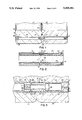
- FIG. 1 is a fragmentary sectional view showing two concrete units joined together
- FIG. 2 is a sectional view showing two precast concrete pipes joined together
- FIG. 3 is an enlarged fragmentary sectional view of a completed joint formed between two precast concrete units;
- FIG. 4 is a sectional view of a second embodiment of a guide member;
- FIG. 5 is a sectional view of a cast-in-place gasket as a joint is being closed;
- FIG. 6 is a cross-sectional view of a gasket which is cast in place when in use;
- FIG. 7 is a sectional view of a second embodiment of a cast-in-place gasket;
- FIG. 8 is a sectional view of an inserted gasket in place between two precast concrete units as a joint is being formed;
- FIG. 9A is a cross-sectional view of a gasket for insertion into a groove formed in a concrete unit;
- FIG. 9B is a gasket similar to that of FIG. 9a with shaped edges;
- FIG. 10A is a sectional view showing possible positions for placement of a gasket in a male and female pipe joint;
- FIG. 10B is a sectional view showing a gasket on a substantially horizontal surface in a male and female joint;
- FIG. 11 is a sectional view of a section of precast concrete box pipe having a tubular member embedded in each corner;
- FIG. 12 is a sectional view of a double precast concrete box pipe having a common wall between each pipe;
- FIG. 13 is a sectional view of a double precast concrete box pipe having a common wall between each pipe and with the pipes being of different sizes;
- FIG. 14 is a partial perspective view of a section of precast pavement;
- FIG. 15 is a partial perspective view of a section of precast decking
- FIG. 16 is a fragmentary view of a concrete unit having a bolt window in the tubular member to facilitate the positioning of the shear bolt;
- FIG. 17 is a partial perspective view of a concrete unit having a bolt window and showing the shear bolt positioned in the guide member;
- FIG. 18 is a schematic elevational view of a keyway joint including a gasket.
- a completed joint 20 is shown between two precast concrete units 21 and 23.
- the concrete units can be sections of a wall panel, pavement or decking such as that used in the assembly of bridges, buildings or parking structures.
- Concrete unit 21 has a tubular member 25 therein which is cast within the concrete when the unit is formed.
- Tubular member 25 is preferably internally threaded at each end 27.
- Tubular member 25 is preferably proportioned to the size of the concrete unit into which it is cast. For example, for a large concrete unit eight to twelve feet long, a steel tube approximately two and one-half inches in outside diameter would be used. The tube would preferably have one-quarter inch wall thickness so the internal diameter of the tube would be two inches.
- Concrete unit 21 is cast with rounded edges 29 to reduce the tendency for chipping along the edge of the unit.
- the edges of cast concrete units, for example pipes, tend to chip in handling which, if bad enough, can make the section of pipe useless.
- a gasket In order to provide a fluid-tight seal between the ends of the concrete units, a gasket should be used.
- the gasket can be embedded into the concrete when it is poured to form the unit or it can be inserted into a groove formed in the face of the concrete unit.
- the inserted gasket is preferred since it ca be added to and locked into the groove in the concrete unit at the construction site prior to joining the concrete units.
- the gaskets 31 are of the type which are inserted into a precast groove 33 in the end of the concrete unit. Groove 33 is provided with diverging walls 35 which provide a space for the gasket material to spread, as shown in concrete unit 23 when the units ar brought together.
- Concrete unit 23 also has a tubular member 25 cast therein at the time it is formed.
- the tubular member like member 25 in concrete member 21, has internally threaded ®nd portions 27.
- an insert member 37 is threaded into tubular member 25 in concrete unit 21.
- Insert member 37 is made of steel and has an externally threaded portion 39 and an axial aperture or bore 41 which has an internal thread 43.
- a guide member 45 is threaded into tubular member 25 in concrete unit 23.
- Guide member 45 has a first threaded portion 47 which can be threaded into the end of tubular member 25 in concrete unit 23.
- Guide member 45 has a shaped end portion 49 which is preferably larger in diameter than threaded portion 47 forming a shoulder 51 which abuts the end of tubular member 25 when the guide member is threaded fully into position in the tubular member.
- a circumferential shear band 53 which provides shear strength to the joint formed between the two concrete units.
- the shear band is approximately one-quarter inch in width.
- the shaped surface of the guide member then slopes toward an edge 55 which abuts the insert member 37 when guide member 45 is inserted into concrete unit 21.
- Guide member 45 has an axial aperture or bore 57 which extends through the guide member and aligns with aperture 42 in insert member 37.
- a port 48 is shown for providing access to the first portion of the guide member for welding it in place in the tubular member.
- a similar port can be provided for welding the insert member in place.
- the edge of the insert member can also be welded in place by reaching in through the open end of the tubular member with a welding rod. The axial shear bolt would still be used for joining the concrete units together.
- a threaded or smooth surfaced tubular member it is important to keep the guide member from turning when the shear bolt is tightened.
- guide member 45 can unscrew out of the tubular member if it turns in the same direction. The rotation of the guide member 45 can be prevented by threading it tightly into the tubular member.
- a small amount of adhesive can be used to glue the guide member in position. Also a small tack weld will hold it in place.
- a lock washer can also be used on the shear bolt between the insert member and the end of the guide member. While the lock washer can function to restrict rotation of the guide member, it is not preferred since it requires the use and handling of another part.
- Insert member 37 is threaded into the end of tubular member 25 in concrete unit 21.
- Guide member 45 is threaded into the end of tubular member 25 in concrete unit 23.
- the concrete units are then brought together bringing end 49 of guide member 45 into the end of tubular member 25 in concrete unit 21.
- Face 55 on the guide member preferably abuts against the face of insert member 39.
- the axial passage 57 in guide member 45 aligns with axial passage 42 in insert member 39.
- a threaded bolt s is then inserted through tubular member 25 in concrete unit 23 and passes through guide member 45 to the internally threaded aperture in insert member 39. The bolt is then tightened to firmly join the two concrete units together.
- another insert member 37 is threaded into the end of tubular member 25 in concrete unit 23 to prepare for the joining of the next concrete unit.
- a slot 59 is provided in the face of the insert member into which a bladed tool can be inserted in order to easily rotate the insert member into position.
- guide member 61 has a threaded portion 63 and a shaped portion 65.
- Shaped portion 65 has a compound surface with a circumferential shear band 67 adjacent the end of tubular member 25 and a sloping surface portion 69 which ends at face 71.
- the overall configuration of the shaped surface is that of a truncated cone with the circumferential sheaf band surrounding the base of the cone.
- Guide member 61 has an axial aperture or bore 73 through which a bolt 58 can be passed for insertion into and tightening into insert member 37.
- sections of precast concrete pipe 81 and 83 are joined together by insert members 39, guide members 45 and bolts 58.
- a gasket 31 surrounds the 10 fluid passage in the connected pipes and is positioned between the fluid passage and the connecting hardware to protect the hardware from water or corrosive materials which might be passing through the pipe.
- the pipe sections are connected from left to right with the joint being made and the bolt being inserted through guide member 45 into internally threaded insert member 39 and then tightened.
- an insert member 37 is inserted into the internally threaded end 27 of tubular members 25 in ? 20 preparation for making the next joint. Insert member 37 is added after bolt 58 is tightened to secure the previously assembled joint. The insert member substantially closes the tubular member once the joint is complete.
- a resilient gasket is preferably placed between the concrete units.
- a fluid-tight joint can be made without the addition or use of mortar or asphalt to seal the faces of the concrete sections forming the joint.
- the gasket is preferably made of a dense rubber-like polymeric material which can resist decomposition by water or, in the case of a pipe, whatever material is passing through the pipe.
- the resilient gasket can be cast in place in the concrete unit when the unit is formed or can be added to a groove formed in the concrete unit.
- FIGS. 5, 6 and 7, two embodiments of a cast-in-place gasket are illustrated.
- the resilient gasket 91 has been cast in place in a concrete unit 93.
- the surface of the concrete unit has a concave 10 depression 95 in which the gasket is centered.
- the cast-in-place gasket has a substantially rectangular base portion 97 which locks the gasket in place in the body of concrete.
- Extending upwardly, as shown in FIG. 5, are a pair of spaced resilient legs 99 which form the seal between concrete units 93 and 101.
- the concave depression in the surface of concrete unit 93 enables legs 99 to bend backward or away from each other, as shown in phantom.
- concrete unit 101 is vertically descending upon concrete unit 93 and gasket 91. The force spreads legs 99 of the gasket outwardly.
- depression 95 provides room for the legs 99 to bend to the left or right in a windshield wiper-like manner to form the seal.
- the depression provides room to accommodate the legs of the gasket so that they are not crushed in forming the joint.
- the legs of the gasket are substantially retained in shape to push against the surface of concrete unit 101 forming a liquid-tight seal.
- the resilient cast-in-place gasket 103 (FIG. 7) has a substantially triangular base portion 105 with a pair of upstanding spaced legs 107 and a center crown 109 along one edge of the gasket.
- the triangular base portion is cast in place in the concrete which again has a relieved or concave surface portion 111 to enable legs 107 to move maintaining a fluid-tight seal without being crushed by the mass of the concrete units.
- a gasket 115 is shown which is inserted into a groove 117 which is formed in the surface of concrete unit 119 when it is cast.
- Groove 117 has a relieved surface 120 with angled walls.
- the bottom of the groove 121 is arcuately shaped.
- Gasket 115 has a pair of spaced legs 123 and an arcuate back portion 125 which substantially conforms to the arcuate configuration of base portion 121 of groove 117.
- a cord of polymeric material 127 commonly referred to as an O-ring cord, is shown in place at the bottom of the groove formed between spaced legs 123.
- gasket 115 In using gasket 115, the gasket is pushed into groove 117 in the surface of the concrete unit.
- the cord of polymeric material 127 is then lubricated with a water or soap solution to facilitate entry of the cord between the spaced legs of the gasket.
- the gasket and the cord are each made of resilient rubber-like material and it is very difficult to insert cord 127 between legs 123 in view of the friction which results from trying to move the rubber-like materials across each other.
- the water soluble lubricant or soap solution facilitates the entry of the cord into the bottom of the groove where it can spread the legs of the gasket, as shown in FIG. 8, to tightly lock the gasket against the sidewalls of groove 117.
- gasket 115 is placed in the groove in the concrete surface of the concrete unit, and is locked in place by cord 127, it is extremely difficult to pull the gasket out of the groove.
- the gasket as shown in FIGS. 8 and 9A, is the preferred gasket since it can be added at the construction site at the last moment before the concrete units are joined together. This maintains the integrity of the gasket and avoids possible damage to the gasket which might occur in shipping and handling.
- the gasket shown in FIG. 9B has sloping edge portions 128. This gasket is preferably used in joining concrete units where the edges will be pushed over like a wiper blade. The sloping end surfaces will tend to align with the face of the concrete unit forming a long seal of material.
- FIGS. 10A and 10B a conventional male and female pipe joint is shown as commonly used with round, precast concrete pipe.
- a first pipe section 131 would have an offset portion 133 while a second concrete pipe 135 would have a tapered portion 137.
- the tapered end is inserted into the opening bounded by the offset portion.
- Gasket 139 is spread open as is gasket 141 by the direct force of the female portion of the pipe pressing against the male portion of the second pipe.
- Gasket 141 is positioned on the face of the tapered portion while gasket 139 is on the face of a surrounding shoulder.
- gasket 143 is on the top surface of the tapered portion and one leg is bent over the O-ring cord material in a windshield wiper-like manner as the two pipes telescope together. The two legs are bent over within the recessed portion of the groove and provide a fluid-tight seal for the pipe.
- FIG. 11 view of a precast concrete box pipe is shown.
- the pipe is substantially square and has a tubular member 25 cast in each corner of the pipe between the edge of the pipe and the haunch 147 of the pipe.
- the tubular member is cast in the concrete as far away from the axial center of the pipe as possible consistent with the strength of the concrete surrounding the tubular member.
- a gasket 31 is o the face of the pipe and is between the fluid passage and tubular members 25 where the joining hardware is assembled. Mounting the gasket in this position prevents any liquid material from contacting the connecting or joining hardware protecting the hardware from rust or corrosion.
- a double box pipe 151 is shown having a fluid passage 153 and 155 separated by a common wall 157.
- fluid passage 159 is substantially larger than fluid passage 161.
- the two fluid passages are separated by a common wall 163 and resilient gaskets which prevent mixing or intermingling of the two fluid streams.
- the double wall or the double box pipe construction is particularly useful in handling both storm drains and sewage.
- the two fluid materials are separated in their passage through the pipe and can be treated separately at the treatment center where they exit the pipe.
- a precast section of pavement 165 which can be used in highway or bridge construction.
- the pavement section has a plurality of tubular members 25 cast into the concrete.
- a gasket 31 surrounds the tubular members since water and other corrosive materials would tend to flow from the surface toward the hardware used to assemble the pavement sections.
- FIG. 15 a precast concrete section of T-type decking 167 is shown which is of the type frequently used in the construction of building and parking structures.
- the section of decking has a wide, substantially flat top 169 which is supported by a vertical section 171.
- a plurality of tubular members 25 have been cast into the section of decking.
- a gasket 31 surrounds the tubular member since, like pavement section 165, water and other corrosive materials will tend to flow down from the surface onto the connecting hardware used to assemble the decking.
- FIG. 16 a second embodiment of the apparatus for joining precast concrete units is shown, for purposes of illustration, in a corner of a precast box pipe.
- a shortened tubular member 181 has been cast into the corner of box pipe section 182 having a bolt window 183 bounded by edge 185.
- a guide member 45 is positioned in the end of tubular member 181, as previously described. Since the bolt window is provided for inserting shear bolt 58, the tubular member does not have to extend fully across the concrete unit for insertion of the bolt into guide member 45 and on through into threaded aperture 42 in insert member 37.
- Insert member 37 is positioned in a shortened tubular member 187 positioned in a corner of a second precast concrete box pipe 189.
- a resilient gasket 191 provides a water-tight seal for the joint.
- bolt window 183 can be covered or filled with polystyrene or other suitable material to prevent concrete from entering into tubular member 181 through aperture 185 which defines the bolt window.
- the concrete can then be poured to form the box pipe.
- the cover can be removed to provide access to the rear of guide member 45 for shear bolt 58.
- the head of bolt 58 has a shaped socket 193 for receiving a Allen-type wrench 194 for tightening bolt 58 into position.
- the bolt window and portion of concrete unit 182 can be filled with concrete and shaped to conform to the rest of the corner of the concrete unit. If it is intended that the concrete units can be disassembled, the bolt window can be covered and then the concrete corner can be completed.
- the shear band on the guide member and the bolt provide the shear strength for the joint. It is within the scope of the present invention to provide a further increase in shear strength by shaping the end faces of the concrete units in a tongue-and-groove manner, as shown in FIG. 18.
- Concrete unit 201 has a projecting key 203 on the end face 205.
- a second concrete unit 207 has a recess or keyway 209 formed in surface 211.
- a resilient gasket 213 is mounted in a shaped groove 215 which has a relieved surface 217 on either side of the groove.
- key 203 When units 201 and 207 are joined together by hardware (not shown) in order to simplify the drawing, key 203 will be positioned in keyway 209. The face of key 203 will press against gasket 213 to provide a fluid-tight seal while the tongue-and-groove fit of 203 and 209 will substantially increase the shear strength of the joint between the concrete units.
- an improved apparatus for connecting precast concrete units.
- the units can be connected using hardware installed on site and are tightly fastened together by bolts.
- the use of bolts substantially simplifies the assembly of the precast concrete units into whatever structure is desired.
- the precast concrete units can be prepared under substantially identical conditions so that each section cures the same way. This is important in pavement sections since the individual sections will expand or contract to the same extent, avoiding unnecessary ridges and bumps which normally occur in highway sections poured at different times of day under different sunlight and moisture conditions.
Landscapes
- Engineering & Computer Science (AREA)
- Architecture (AREA)
- General Engineering & Computer Science (AREA)
- Civil Engineering (AREA)
- Structural Engineering (AREA)
- Mechanical Engineering (AREA)
- Physics & Mathematics (AREA)
- Electromagnetism (AREA)
- Sewage (AREA)
- Bridges Or Land Bridges (AREA)
- Road Paving Structures (AREA)
Abstract
Description
Claims (14)
Priority Applications (7)
| Application Number | Priority Date | Filing Date | Title |
|---|---|---|---|
| US07/842,086 US5309691A (en) | 1992-02-26 | 1992-02-26 | Shear connected structural units |
| MX9301038A MX9301038A (en) | 1992-02-26 | 1993-02-25 | PRE-COLLECTED CONCRETE UNITS CONNECTED WITH SAFETY PIN. |
| CA002090520A CA2090520A1 (en) | 1992-02-26 | 1993-02-26 | Shear bolt connected precast concrete units |
| EP93301490A EP0558344A1 (en) | 1992-02-26 | 1993-02-26 | Apparatus for joining precast concrete units |
| US08/239,049 US5634312A (en) | 1992-02-26 | 1994-05-06 | Shear bolt connected structural units |
| US08/444,955 US5537794A (en) | 1992-02-26 | 1995-05-19 | Shear bolt connected structural units |
| US08/467,601 US5682635A (en) | 1992-02-26 | 1995-06-06 | Bridge and road construction and method of removing worn deck structure |
Applications Claiming Priority (1)
| Application Number | Priority Date | Filing Date | Title |
|---|---|---|---|
| US07/842,086 US5309691A (en) | 1992-02-26 | 1992-02-26 | Shear connected structural units |
Related Child Applications (3)
| Application Number | Title | Priority Date | Filing Date |
|---|---|---|---|
| US08/239,049 Continuation-In-Part US5634312A (en) | 1992-02-26 | 1994-05-06 | Shear bolt connected structural units |
| US08/239,049 Division US5634312A (en) | 1992-02-26 | 1994-05-06 | Shear bolt connected structural units |
| US08/444,955 Continuation-In-Part US5537794A (en) | 1992-02-26 | 1995-05-19 | Shear bolt connected structural units |
Publications (1)
| Publication Number | Publication Date |
|---|---|
| US5309691A true US5309691A (en) | 1994-05-10 |
Family
ID=25286494
Family Applications (3)
| Application Number | Title | Priority Date | Filing Date |
|---|---|---|---|
| US07/842,086 Expired - Fee Related US5309691A (en) | 1992-02-26 | 1992-02-26 | Shear connected structural units |
| US08/239,049 Expired - Fee Related US5634312A (en) | 1992-02-26 | 1994-05-06 | Shear bolt connected structural units |
| US08/444,955 Expired - Fee Related US5537794A (en) | 1992-02-26 | 1995-05-19 | Shear bolt connected structural units |
Family Applications After (2)
| Application Number | Title | Priority Date | Filing Date |
|---|---|---|---|
| US08/239,049 Expired - Fee Related US5634312A (en) | 1992-02-26 | 1994-05-06 | Shear bolt connected structural units |
| US08/444,955 Expired - Fee Related US5537794A (en) | 1992-02-26 | 1995-05-19 | Shear bolt connected structural units |
Country Status (4)
| Country | Link |
|---|---|
| US (3) | US5309691A (en) |
| EP (1) | EP0558344A1 (en) |
| CA (1) | CA2090520A1 (en) |
| MX (1) | MX9301038A (en) |
Cited By (13)
| Publication number | Priority date | Publication date | Assignee | Title |
|---|---|---|---|---|
| US5537794A (en) * | 1992-02-26 | 1996-07-23 | Independent Concrete Pipe Company | Shear bolt connected structural units |
| US5635097A (en) | 1995-02-14 | 1997-06-03 | Concrete Structures Of The Midwest, Inc. | Rebar retention apparatus |
| US6065263A (en) * | 1997-06-27 | 2000-05-23 | Kaieitechno Co., Ltd. | Connecting structure for concrete block and connector used therefor |
| US20090139177A1 (en) * | 2007-11-29 | 2009-06-04 | Barsplice Products, Inc. | Coupler system for adjacent precast concrete members and method of connecting |
| US20150001822A1 (en) * | 2013-06-28 | 2015-01-01 | GM Global Technology Operations LLC | Drainable section stabilizer sleeve |
| US20150013243A1 (en) * | 2012-11-13 | 2015-01-15 | Dirtt Environmental Solutions, Ltd. | Selectively adjustable architectural wall |
| US9267283B1 (en) * | 2014-12-11 | 2016-02-23 | Thomas Kentz | Kit for precast panels and method of assembling panels |
| JP2016098490A (en) * | 2014-11-18 | 2016-05-30 | 株式会社ピーエス三菱 | Construction method for concrete floor slab of overpass |
| US10760264B2 (en) * | 2018-01-31 | 2020-09-01 | Hefei Construction Engineering Group Co.Ltd | Assembling structure of prefabricated concrete component |
| CN112996966A (en) * | 2018-09-14 | 2021-06-18 | Nxt建筑系统有限公司 | Connecting piece for connecting prefabricated wall boards |
| CN114855594A (en) * | 2022-05-11 | 2022-08-05 | 北京建筑大学 | Steel-concrete composite beam bridge shear connector and construction method thereof |
| CN116591020A (en) * | 2023-04-23 | 2023-08-15 | 福州大学 | Fast assembly connection structure and manufacturing method of prefabricated concrete thin slab and steel pipe |
| JP2024081942A (en) * | 2022-12-07 | 2024-06-19 | 三井住友建設株式会社 | Method for connecting a pipe included in a structure to a pipe included in another structure |
Families Citing this family (18)
| Publication number | Priority date | Publication date | Assignee | Title |
|---|---|---|---|---|
| GB2295845B (en) * | 1994-12-06 | 1998-08-19 | Christopher Alan Goodland | Fastening device |
| AU8823198A (en) * | 1997-07-28 | 1999-02-16 | Interface, Inc. | Perforated raised flooring panel |
| US6256952B1 (en) | 1998-07-27 | 2001-07-10 | Interface, Inc. | Perforated raised flooring panel |
| JP2000054795A (en) * | 1998-08-11 | 2000-02-22 | Ohbayashi Corp | Segment |
| DE10029343C2 (en) * | 2000-06-20 | 2003-01-30 | Induo Ges Zur Verwertung Von S | Connection for firmly connecting at least two elements |
| US7260919B1 (en) * | 2002-04-16 | 2007-08-28 | Daw Technologies, Inc. | Sealable ceiling assembly |
| DE102005014900A1 (en) * | 2005-04-01 | 2006-10-05 | Induo Gesellschaft Zur Verwertung Von Schutzrechten Mbh & Co Kg | Composite anchor for connecting at least two components and system of interconnected components |
| US7886496B1 (en) | 2007-08-20 | 2011-02-15 | Daw Technologies, Inc. | Extruded aluminum bottom-load ceiling |
| GB0717254D0 (en) * | 2007-09-05 | 2007-10-17 | Ancon Ltd | Sheer connector |
| AT511220B1 (en) * | 2011-04-08 | 2013-01-15 | Cree Gmbh | CEILING ELEMENT FOR THE EDUCATION OF BUILDING COVERS |
| WO2015168742A1 (en) * | 2014-05-08 | 2015-11-12 | Grw Manufacturing Pty Ltd | Panel connection device |
| US9553374B1 (en) | 2015-11-19 | 2017-01-24 | Tyco Electronics Canada Ulc | Electrical connectors and connection assemblies and methods including the same |
| EP3954839A1 (en) * | 2016-04-28 | 2022-02-16 | Lucobit AG | System for wall to wall connection for precast shear walls and method thereof |
| CN107724541B (en) * | 2017-10-23 | 2023-05-02 | 能诚集团有限公司 | Building element connection structure |
| US11821449B1 (en) * | 2019-11-27 | 2023-11-21 | Meadow Burke, Llc | Lockable double shear dowel connector |
| CN111501556B (en) * | 2020-03-23 | 2021-07-02 | 江苏永捷工程物流有限公司 | Assembly equipment for segment prefabricated assembly bridge joint structure |
| CN112252485A (en) * | 2020-10-22 | 2021-01-22 | 闫锋 | Anti-cracking prestressed precast concrete member |
| CN113152745B (en) * | 2021-03-18 | 2022-06-14 | 深圳景源达建设集团有限公司 | Connecting device for decorative aluminum plate and overpass curtain wall and construction method thereof |
Citations (18)
| Publication number | Priority date | Publication date | Assignee | Title |
|---|---|---|---|---|
| US1579285A (en) * | 1923-10-03 | 1926-04-06 | Timothy A Danaher | Conduit |
| US2158302A (en) * | 1937-05-01 | 1939-05-16 | Ralph S Peirce | Anchoring for concrete or the like |
| CA645343A (en) * | 1962-07-24 | J. Wilhelm Hilmar | Adjustable concrete inserts | |
| GB1004186A (en) * | 1963-02-27 | 1965-09-08 | Audax Ltd | Improvements relating to tie rod assemblies for shuttering for casting concrete |
| US3333388A (en) * | 1965-01-13 | 1967-08-01 | Herbert J Sandin | Concrete block anchoring means for a wall plate or cap |
| GB1410970A (en) * | 1972-12-29 | 1975-10-22 | Cercelet A | Construction of buildings |
| GB1473861A (en) * | 1974-04-18 | 1977-05-18 | Henriksson A | Device for connecting building elements |
| US4047388A (en) * | 1976-06-30 | 1977-09-13 | Howlett Machine Works | Method for coupling axially aligned tunnel sections and apparatus therefor |
| US4199158A (en) * | 1977-11-23 | 1980-04-22 | Vredestein N.V. | Profiled gasket for sealing tunnel segment joints |
| GB2100772A (en) * | 1981-06-22 | 1983-01-06 | Charcon Tunnels Ltd | Improvements in or relating to arcuate lining segments for shafts or tunnels |
| US4496259A (en) * | 1980-05-28 | 1985-01-29 | Alsthom-Atlantique | Connector for connecting two rotors together |
| US4497590A (en) * | 1982-03-08 | 1985-02-05 | Crs Group, Inc. | Tunnel lining |
| US4606671A (en) * | 1983-06-06 | 1986-08-19 | Danfoss A/S | Coupling for connecting a hub and shaft |
| US4781006A (en) * | 1986-11-10 | 1988-11-01 | Haynes Harvey H | Bolted chord bar connector for concrete construction |
| US4830536A (en) * | 1981-08-07 | 1989-05-16 | Commercial Shearing, Inc. | Method and apparatus for tunnel lining |
| US4900607A (en) * | 1987-09-05 | 1990-02-13 | Phoenix Aktiengesellschaft | Sealing profile |
| US4946309A (en) * | 1985-01-26 | 1990-08-07 | Phoenix Aktiegesellschaft | Sealing profile |
| US5134828A (en) * | 1990-12-14 | 1992-08-04 | High Industries, Inc. | Connection for joining precast concrete panels |
Family Cites Families (25)
| Publication number | Priority date | Publication date | Assignee | Title |
|---|---|---|---|---|
| US342280A (en) * | 1886-05-18 | Electrical conduit | ||
| US2732230A (en) * | 1956-01-24 | Recessed joint for concrete pipe | ||
| US1120471A (en) * | 1914-04-23 | 1914-12-08 | William Henry Franklin | Culvert. |
| US1144200A (en) * | 1915-01-20 | 1915-06-22 | William S Hewett | Culvert. |
| US1271708A (en) * | 1917-07-09 | 1918-07-09 | Herman Dick Horstman | Burial-vault. |
| US1443162A (en) * | 1919-10-09 | 1923-01-23 | Arthur S Bent | Conduit |
| US1441736A (en) * | 1922-09-07 | 1923-01-09 | James Knapp | Pipe coupling |
| US1774664A (en) * | 1926-03-18 | 1930-09-02 | Walter C Parmley | Joint for conduits |
| US1765664A (en) * | 1926-09-11 | 1930-06-24 | Otto S Flath | Signal foundation |
| US1670625A (en) * | 1926-11-12 | 1928-05-22 | Johannesson Sigvald | Tunnel lining |
| US2042132A (en) * | 1933-04-12 | 1936-05-26 | Treskow Robert | Pipe joint |
| US2005699A (en) * | 1934-03-01 | 1935-06-18 | Ric Wil Company | Conduit and like construction |
| US2488245A (en) * | 1947-10-06 | 1949-11-15 | Standard Concrete Products Cor | Pipe joint |
| US3090646A (en) * | 1960-09-09 | 1963-05-21 | Gen Motors Corp | Means for securing convertible top fabric |
| US3502356A (en) * | 1967-11-02 | 1970-03-24 | Hancock Brick & Tile Co | Plain end sewer pipes and coupling for same |
| US3567233A (en) * | 1968-07-11 | 1971-03-02 | Fred C Stepanich | Gasket means for pipe |
| US3677581A (en) * | 1970-09-30 | 1972-07-18 | Thomas K Breitfuss | Keyed joint arrangement for interconnecting pipe sections |
| GB1393287A (en) * | 1972-08-15 | 1975-05-07 | Charcon Tunnels Ltd | Arcuate tunnel lining segments |
| US4026582A (en) * | 1975-08-11 | 1977-05-31 | Nippon Concrete Industries Co. Ltd. | Connected part of concrete pipe |
| AT349861B (en) * | 1976-05-25 | 1979-04-25 | Evg Entwicklung Verwert Ges | BINDING TOOL FOR TWISTING THE FREE ENDS OF A BINDING WIRE AND LATTICE TYING MACHINE WITH SUCH TOOLS |
| US4070848A (en) * | 1977-04-28 | 1978-01-31 | Lingle Cleo M | Fastening bar assembly for frameless insulating panels |
| US4475329A (en) * | 1982-07-14 | 1984-10-09 | Artur Fischer | Anchoring expansible fastener |
| JPS5948599A (en) * | 1982-08-06 | 1984-03-19 | 都築 純一 | Tunnel covering construction structure |
| US4930677A (en) * | 1988-05-16 | 1990-06-05 | Jolliffee Michael J A H | Concrete connector |
| US5309691A (en) * | 1992-02-26 | 1994-05-10 | Tolliver Wilbur E | Shear connected structural units |
-
1992
- 1992-02-26 US US07/842,086 patent/US5309691A/en not_active Expired - Fee Related
-
1993
- 1993-02-25 MX MX9301038A patent/MX9301038A/en not_active IP Right Cessation
- 1993-02-26 CA CA002090520A patent/CA2090520A1/en not_active Abandoned
- 1993-02-26 EP EP93301490A patent/EP0558344A1/en not_active Withdrawn
-
1994
- 1994-05-06 US US08/239,049 patent/US5634312A/en not_active Expired - Fee Related
-
1995
- 1995-05-19 US US08/444,955 patent/US5537794A/en not_active Expired - Fee Related
Patent Citations (18)
| Publication number | Priority date | Publication date | Assignee | Title |
|---|---|---|---|---|
| CA645343A (en) * | 1962-07-24 | J. Wilhelm Hilmar | Adjustable concrete inserts | |
| US1579285A (en) * | 1923-10-03 | 1926-04-06 | Timothy A Danaher | Conduit |
| US2158302A (en) * | 1937-05-01 | 1939-05-16 | Ralph S Peirce | Anchoring for concrete or the like |
| GB1004186A (en) * | 1963-02-27 | 1965-09-08 | Audax Ltd | Improvements relating to tie rod assemblies for shuttering for casting concrete |
| US3333388A (en) * | 1965-01-13 | 1967-08-01 | Herbert J Sandin | Concrete block anchoring means for a wall plate or cap |
| GB1410970A (en) * | 1972-12-29 | 1975-10-22 | Cercelet A | Construction of buildings |
| GB1473861A (en) * | 1974-04-18 | 1977-05-18 | Henriksson A | Device for connecting building elements |
| US4047388A (en) * | 1976-06-30 | 1977-09-13 | Howlett Machine Works | Method for coupling axially aligned tunnel sections and apparatus therefor |
| US4199158A (en) * | 1977-11-23 | 1980-04-22 | Vredestein N.V. | Profiled gasket for sealing tunnel segment joints |
| US4496259A (en) * | 1980-05-28 | 1985-01-29 | Alsthom-Atlantique | Connector for connecting two rotors together |
| GB2100772A (en) * | 1981-06-22 | 1983-01-06 | Charcon Tunnels Ltd | Improvements in or relating to arcuate lining segments for shafts or tunnels |
| US4830536A (en) * | 1981-08-07 | 1989-05-16 | Commercial Shearing, Inc. | Method and apparatus for tunnel lining |
| US4497590A (en) * | 1982-03-08 | 1985-02-05 | Crs Group, Inc. | Tunnel lining |
| US4606671A (en) * | 1983-06-06 | 1986-08-19 | Danfoss A/S | Coupling for connecting a hub and shaft |
| US4946309A (en) * | 1985-01-26 | 1990-08-07 | Phoenix Aktiegesellschaft | Sealing profile |
| US4781006A (en) * | 1986-11-10 | 1988-11-01 | Haynes Harvey H | Bolted chord bar connector for concrete construction |
| US4900607A (en) * | 1987-09-05 | 1990-02-13 | Phoenix Aktiengesellschaft | Sealing profile |
| US5134828A (en) * | 1990-12-14 | 1992-08-04 | High Industries, Inc. | Connection for joining precast concrete panels |
Cited By (19)
| Publication number | Priority date | Publication date | Assignee | Title |
|---|---|---|---|---|
| US5537794A (en) * | 1992-02-26 | 1996-07-23 | Independent Concrete Pipe Company | Shear bolt connected structural units |
| US5635097A (en) | 1995-02-14 | 1997-06-03 | Concrete Structures Of The Midwest, Inc. | Rebar retention apparatus |
| US6065263A (en) * | 1997-06-27 | 2000-05-23 | Kaieitechno Co., Ltd. | Connecting structure for concrete block and connector used therefor |
| US6327829B1 (en) | 1997-06-27 | 2001-12-11 | Kaieitechno Co., Ltd. | Connecting structure for concrete block and connector used therefor |
| US20090139177A1 (en) * | 2007-11-29 | 2009-06-04 | Barsplice Products, Inc. | Coupler system for adjacent precast concrete members and method of connecting |
| US7975444B2 (en) * | 2007-11-29 | 2011-07-12 | Barsplice Products, Inc. | Coupler system for adjacent precast concrete members and method of connecting |
| US9803360B2 (en) * | 2012-11-13 | 2017-10-31 | Dirtt Environmental Solutions, Ltd. | Selectively adjustable architectural wall |
| US20150013243A1 (en) * | 2012-11-13 | 2015-01-15 | Dirtt Environmental Solutions, Ltd. | Selectively adjustable architectural wall |
| US20150001822A1 (en) * | 2013-06-28 | 2015-01-01 | GM Global Technology Operations LLC | Drainable section stabilizer sleeve |
| US9428224B2 (en) * | 2013-06-28 | 2016-08-30 | GM Global Technology Operations LLC | Drainable section stabilizer sleeve |
| JP2016098490A (en) * | 2014-11-18 | 2016-05-30 | 株式会社ピーエス三菱 | Construction method for concrete floor slab of overpass |
| US9267283B1 (en) * | 2014-12-11 | 2016-02-23 | Thomas Kentz | Kit for precast panels and method of assembling panels |
| US10760264B2 (en) * | 2018-01-31 | 2020-09-01 | Hefei Construction Engineering Group Co.Ltd | Assembling structure of prefabricated concrete component |
| CN112996966A (en) * | 2018-09-14 | 2021-06-18 | Nxt建筑系统有限公司 | Connecting piece for connecting prefabricated wall boards |
| EP3850165A4 (en) * | 2018-09-14 | 2022-05-18 | NXT Building System Pty Ltd. | PREFABRICATED WALL PANELS JOINT JOINT |
| AU2019339917B2 (en) * | 2018-09-14 | 2023-09-21 | Nxt Building System Pty Ltd | A connection for connecting precast wall panels |
| CN114855594A (en) * | 2022-05-11 | 2022-08-05 | 北京建筑大学 | Steel-concrete composite beam bridge shear connector and construction method thereof |
| JP2024081942A (en) * | 2022-12-07 | 2024-06-19 | 三井住友建設株式会社 | Method for connecting a pipe included in a structure to a pipe included in another structure |
| CN116591020A (en) * | 2023-04-23 | 2023-08-15 | 福州大学 | Fast assembly connection structure and manufacturing method of prefabricated concrete thin slab and steel pipe |
Also Published As
| Publication number | Publication date |
|---|---|
| MX9301038A (en) | 1993-11-01 |
| EP0558344A1 (en) | 1993-09-01 |
| US5537794A (en) | 1996-07-23 |
| CA2090520A1 (en) | 1993-08-27 |
| US5634312A (en) | 1997-06-03 |
Similar Documents
| Publication | Publication Date | Title |
|---|---|---|
| US5309691A (en) | Shear connected structural units | |
| US5682635A (en) | Bridge and road construction and method of removing worn deck structure | |
| US5493838A (en) | Method of constructing a concrete basement from prefabricated concrete panels | |
| US2920475A (en) | Building panel | |
| RU2544945C2 (en) | Turnbuckle to connect structural elements | |
| US4661008A (en) | Joint structure for channels | |
| JPS59217836A (en) | Underground structure | |
| JP2891670B2 (en) | Flexible joint structure of concrete product and concrete product having the flexible joint structure | |
| JPH04106236A (en) | Prefabricated underground structure | |
| KR200402713Y1 (en) | connection structure of pipe for a manhole | |
| JPS636261Y2 (en) | ||
| JPH0715845U (en) | Assembly manhole | |
| JPH0352884Y2 (en) | ||
| JPH0476119A (en) | Joining structure of block structure for constructing foundation | |
| JPS583884Y2 (en) | Side block for manhole | |
| JPH0115764Y2 (en) | ||
| JPH0141786Y2 (en) | ||
| KR101960698B1 (en) | Joint structure of underground culvert | |
| JPH0432401Y2 (en) | ||
| JPS6038771Y2 (en) | concrete block | |
| JPH0558701U (en) | Floor material | |
| JP2779836B2 (en) | Concrete product joining structure to fill the void | |
| JPH0421917Y2 (en) | ||
| JPH0427022A (en) | Structure of concrete assembly-type basement | |
| SE1651036A1 (en) | Method of providing a liquid proof joint between parts and structure comprising such joint |
Legal Events
| Date | Code | Title | Description |
|---|---|---|---|
| AS | Assignment |
Owner name: INDEPENDENT CONCRETE PIPE CORPORATION, INDIANA Free format text: ASSIGNMENT OF ASSIGNORS INTEREST;ASSIGNOR:MAGNUSON, LARRY R.;REEL/FRAME:006627/0243 Effective date: 19930713 Owner name: INDEPENDENT CONCRETE PIPE CORPORATION, INDIANA Free format text: ASSIGNMENT OF ASSIGNORS INTEREST;ASSIGNOR:TOLLIVER, WILBUR E.;REEL/FRAME:006627/0250 Effective date: 19930728 |
|
| AS | Assignment |
Owner name: INDEPENDENT CONCRETE PIPE CORPORATION, INDIANA Free format text: ASSIGNMENT OF ASSIGNORS INTEREST;ASSIGNOR:TOLLIVER, WILBUR E.;REEL/FRAME:007014/0030 Effective date: 19930713 Owner name: INDEPENDENT CONCRETE PIPE CORPORATION, INDIANA Free format text: ASSIGNMENT OF ASSIGNORS INTEREST;ASSIGNOR:MAGNUSON, LARRY R.;REEL/FRAME:007014/0033 Effective date: 19930713 |
|
| CC | Certificate of correction | ||
| AS | Assignment |
Owner name: NBN BANK, N.A., INDIANA Free format text: SECURITY INTEREST;ASSIGNOR:INDEPENDENT CONCRETE PIPE CORPORATION;REEL/FRAME:007197/0032 Effective date: 19941202 |
|
| FPAY | Fee payment |
Year of fee payment: 4 |
|
| REMI | Maintenance fee reminder mailed | ||
| LAPS | Lapse for failure to pay maintenance fees | ||
| STCH | Information on status: patent discontinuation |
Free format text: PATENT EXPIRED DUE TO NONPAYMENT OF MAINTENANCE FEES UNDER 37 CFR 1.362 |
|
| FP | Lapsed due to failure to pay maintenance fee |
Effective date: 20020510 |