US5309105A - Vibration reduction system for magnetic-resonance imaging apparatus - Google Patents
Vibration reduction system for magnetic-resonance imaging apparatus Download PDFInfo
- Publication number
- US5309105A US5309105A US07/910,543 US91054392A US5309105A US 5309105 A US5309105 A US 5309105A US 91054392 A US91054392 A US 91054392A US 5309105 A US5309105 A US 5309105A
- Authority
- US
- United States
- Prior art keywords
- bobbin
- rigid connection
- hollow
- tubes
- support member
- Prior art date
- Legal status (The legal status is an assumption and is not a legal conclusion. Google has not performed a legal analysis and makes no representation as to the accuracy of the status listed.)
- Expired - Lifetime
Links
Images


Classifications
-
- G—PHYSICS
- G01—MEASURING; TESTING
- G01R—MEASURING ELECTRIC VARIABLES; MEASURING MAGNETIC VARIABLES
- G01R33/00—Arrangements or instruments for measuring magnetic variables
- G01R33/20—Arrangements or instruments for measuring magnetic variables involving magnetic resonance
- G01R33/28—Details of apparatus provided for in groups G01R33/44 - G01R33/64
- G01R33/38—Systems for generation, homogenisation or stabilisation of the main or gradient magnetic field
- G01R33/385—Systems for generation, homogenisation or stabilisation of the main or gradient magnetic field using gradient magnetic field coils
- G01R33/3854—Systems for generation, homogenisation or stabilisation of the main or gradient magnetic field using gradient magnetic field coils means for active and/or passive vibration damping or acoustical noise suppression in gradient magnet coil systems
Definitions
- the present invention relates to a magnetic-resonance imaging apparatus.
- a magnetic-resonance imaging apparatus In a magnetic-resonance imaging apparatus, a strong uniform magnetic field is generated in a predetermined volume, and then a magnetic field gradient is generated within that volume to induce magnetic resonance in an object to be investigated. The resonance is then analyzed to determine the properties of the object.
- a magnetic-resonance imaging apparatus finds particular applicability for medical purposes as it represents a non-invasive method for investigating the interior of a human body.
- a support known as a bobbin which is in the form of a hollow cylinder, so that the coils may be secured to the inner or outer cylindrical surface thereof.
- the bobbin is usually made of epoxy resin having a very high elastic modulus. Examples of such magnetic-resonance imaging apparatuses are disclosed in, for example, JP-A-62-261105, JP-A-62-229906, JP-A-62-239503 and JP-A-63-158047.
- JP-A-61-279238 proposed that a rubber pad be interposed between the bobbin and each coil which generated the magnetic field gradient.
- the coil could move relative to the bobbin, due to deformation of the pad and the vibrations thus generated were damped by the rubber pad.
- the support for the coils e.g. the bobbin
- the support for the coils includes a hollow part (hollow enclosure), within which hollow part are movable bodies.
- the movable bodies are preferably granules or other particulate material.
- the present invention When forces are generated on the coils which tend to induce vibration, the present invention provides rigid interconnection of the coils and support to prevent the coils vibrating relative to the support. Hence, the accuracy of positioning of the magnetic field gradients is not impaired. Instead, the vibrational energy is transmitted to the moving bodies which then move within their hollow enclosure, thereby dissipating the vibrational energy. Thus, the present invention is based on the dissipation of vibrational energy by moving bodies within a hollow enclosure, thereby permitting rigid interconnection of the coils and support.
- the part of the support containing the movable bodies is the part to which the coils are attached to the support, since this ensures that the maximum amount of vibrational energy is transmitted to the moving bodies.
- the support it is possible for the support to have some or all the bodies within parts which are not directly attached to the coils. Even in this case, the movable bodies will dissipate vibrational energy.
- a plurality of hollow tubes may be provided on a cylindrical surface of that bobbin, with there being a sufficient number of tubes wholly to cover the cylindrical surface.
- the hollow tubes contain movable bodies, e.g. particulate material.
- the coils for generating magnetic field gradients are attached to some (not necessarily all) of the tubes.
- the tubes to which the coils are attached then receive directly vibrational energy from the coils, when current pulses are passed through those coils, but the other tubes, not attached to the coils, will also receive vibrational energy transmitted via the bobbin itself, or possibly via adjacent tubes. Hence, vibrational energy can be dissipated efficiently by the movable bodies in the tubes.
- the hollow part of the support containing the movable bodies is formed by a plurality of discrete members to which parts of the coils are attached. It is also possible that the bobbin itself is at least partially hollow, and contains movable bodies, or even for the movable bodies to be contained in a part of the support not directly attached to the coils. In these latter cases, however, the noise dissipation effect is reduced.
- the movable bodies are formed by particulate material e.g. granules.
- particulate material e.g. granules.
- the granules themselves will generate noise as they move within the hollow part of the support and therefore it may be desirable to include a liquid, such as water or oil, within the hollow part of the support which contains the movable bodies.
- a liquid such as water or oil
- the noise dissipation effect achieved by the use of moveable bodies within the support increases with an increase in mass of the movable bodies. Therefore, the number of movable bodies, and the density thereof, should be as high as possible. Of course, if the hollow interior of the support is wholly packed with the bodies, then they will not be able to move and the noise dissipation effect will be reduced. However, it has been found that the noise dissipation effect reaches a maximum when the volume of the bodies represents about 90% of the volume of the hollow interior of the support. To maximize the mass, the use of dense materials such as lead (Pb) is preferable, although Al 2 O 3 and Zirconia may be used.
- Pb lead
- FIG. 1 shows, partially in section, a magnetic-resonance imaging apparatus being a first embodiment of the present invention
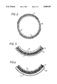
- FIG. 2 shows a sectional view of part of the apparatus of FIG. 1;
- FIG. 3 shows, in detail, part of the section of FIG. 2;
- FIG. 4 is similar to FIG. 3, but illustrates a modification of the embodiments of FIGS. 1 to 3;
- FIG. 5 shows part of a magnetic-resonance imaging apparatus being a second embodiment of the present invention
- FIG. 6 shows part of a magnetic-resonance imaging apparatus being a third embodiment of the present invention.
- FIG. 7 shows a mounting member used in the embodiment of FIG. 6.
- FIGS. 8-11 show structures for enclosing particulate material, which may be used in the embodiments of the present invention.
- FIG. 1 shows the general structure of a magnetic-resonance imaging apparatus being a first embodiment of the present invention.
- the outer casing is shown in sectional view so that the internal structure of the apparatus can be seen. Furthermore, part of that internal structure is itself shown in sectional view.
- a cryostat 1 which is vacuum insulated, contains a bath of liquid helium 2.
- Superconducting magnets 3 are located within that liquid helium, and generate a static uniform magnetic field.
- the liquid helium cools the superconducting magnets 3.
- the superconducting magnets 3 are such as to generate a constant magnetic field of e.g. 0.5 to 4 Tesla within a space 5 defined by the hollow interior of the cryostat 1. That magnetic field is in the axial direction (i.e. the Z direction in FIG. 1).
- coils 7 are illustrated which generate gradients in the Y-direction. However, in addition to those coils 7, there will also be coils for generating magnetic field gradients in the X and Z directions, but these coils are not illustrated to simplify FIG. 1.
- the coils 7 are mounted on a bobbin 8, which bobbin 8 is in the form of a hollow cylinder.
- tubes 10 are mounted on the outer cylindrical surface of the bobbin 8, and the coils 7 are then mounted on the tubes 10.
- Suitable securing means such as a band or bands, secures together the bobbin 8 and the tubes 10, and a similar band or bands (again, not shown) secures together the coils 7 and the bobbin 8, via the tubes 10.
- Both ends of the bobbin 8 are connected to the inside of the cryostat 1 by securing bolts 11, thereby aligning the axis of the coils 7 relative to the direction of the magnet field generated by the superconducting magnets 3.
- a suitable outer shield 12 of e.g. iron is provided around the cryostat 1, to reduce magnetic field leakage.
- the coils 7 are in the form of a loop and are curved around the outer surface of the bobbin 8. Hence, they have a saddle-like shape.
- a current pulse i is applied to the coils 7.
- Fleming's left hand rule that a force will be generated on the left hand branch 7a of the lower left coil 7, which force is axially inward.
- the force generated on the right hand branch 7b will be axially outward. If the coil 7 was not attached to the bobbin 8 via the tubes 10, it could deform, which would result in distortion of the magnetic field gradient, thereby reducing the accuracy of image generation.
- the tubes 10 have a high rigidity, the deformation of the coils 7 is sufficiently small that the distortion of the magnetic field gradient is insignificant. As a result, high-quality images can be obtained.
- the tubes 10 are hollow and contain particulate material, e.g. granules 6.
- the granules 6 are movable within the tubular members 8, and thereby absorb vibrational energy.
- FIG. 3 shows that the tubular members 10 are partially filled with granules 6 and when vibrational energy is transmitted between the coils 7 and the bobbin 8, the granules 6 move, causing collisions therebetween, and thereby dissipating vibrational energy.
- the granules 6 decrease the vibrational energy transmitted from the coils 7 to the bobbin 8.
- vibration of the bobbin 8 is reduced and noise generated by the magnetic resonance imaging apparatus is reduced.
- the noise-reducing effect of the embodiments of FIGS. 1 to 3 increases with increasing mass of the granules 6 within the tubes 10. Therefore, it is preferable for the granules 6 to be of a material of high density, such as lead (Pb). However, Al 2 O 3 or Zirconium may also be used. Furthermore, the noise-reducing effect increases with increasing volume of granules, up to about 90% of the volume of the interior of the tubes 10. Above about 90%, the noise-reducing effect decreases because the freedom of movement of the granules 6 becomes limited. If the granules were packed sufficiently densely within the tubes 10 that they could not move, the noise reducing effect will be lost.
- the coils are mounted, via the tubes 10, on the outer cylindrical surface of the bobbin 8.
- the coils 7 it is also possible for the coils 7 to be mounted on the inner cylindrical surface, as shown in FIG. 4. Again, tubes 10 containing granules 6 are interposed between the coils 7 and bobbin 8.
- FIG. 5 shows an embodiment in which the tubes 10 extend circumferentially around the bobbin. Again, the tubes 10 may be on the outer cylindrical surface of the bobbin 8, as in FIG. 5, or on the inner cylindrical surface (not shown).
- the coils 7 are attached to the bobbin 8 via tubes 10.
- FIG. 6 shows another embodiment, in which the coils 7 are attached to the bobbin 8 via mounting members 13. These mounting members 13 are discrete hollow members and, as shown in FIG. 7, contains granules 6 in a similar way to the tubes 10 of the embodiments FIGS. 1 to 5.
- the mounting members 13 form a rigid interconnection between the coils 7 and bobbin 8, thereby preventing distortion of the magnetic field gradients generated by the coils 7. Again, movement of the granules 6 gives a noise-reducing effect. However, since the volume of the granules 6 is more limited in the embodiment of FIGS. 6 and 7, as compared with the embodiments of FIGS. 1 to 5, the noise-reducing effect is less pronounced.
- the tubes 10 may be partially filled with liquid 14 as shown in FIG. 8.
- FIG. 9 shows an embodiment in which there is powder material 15 within the tubes 10, in addition to the granules 6.
- the use of such powder material 15 reduces the noise due to collision between granules, and also prevents the granules 6 from blocking together within the tubes 10.
- non-granular bodies such as e.g. rods within the tubes 10 or mounting members 13, although this is not preferred as such rods have more limited movement, and so give a smaller noise-reduction effect.
- tubes 10 When tubes 10 are used, they are preferably cylindrical but may be square or, indeed, any other shape.
- FIG. 10 shows an arrangement in which a corrugated sheet 16 with a covering 17 encloses the granules 6. The arrangement of FIG. 10 may then replace the tubular members 10 in any of the embodiments of FIGS. 1 to 5.
- the tubes 10 may be discrete but are preferably interconnected by connections 18 as shown in FIG. 11, so that vibrational energy may be transmitted between the tubes 10.
- the present invention it is possible to obtain high-quality images free from distortion of the magnetic fields due to movement of the coils which generate the magnet field gradient, despite the force generated when current pulses are applied to those coils, since the coils are rigidly connected to the bobbin or other support.
- the use of support with a hollow part containing moveable bodies, such as granules reduces noises generated by the apparatus.
Landscapes
- Physics & Mathematics (AREA)
- Condensed Matter Physics & Semiconductors (AREA)
- General Physics & Mathematics (AREA)
- Magnetic Resonance Imaging Apparatus (AREA)
Applications Claiming Priority (2)
| Application Number | Priority Date | Filing Date | Title |
|---|---|---|---|
| JP3169617A JP2982392B2 (ja) | 1991-07-10 | 1991-07-10 | 磁気共鳴イメージング装置 |
| JP3-169617 | 1991-07-10 |
Publications (1)
| Publication Number | Publication Date |
|---|---|
| US5309105A true US5309105A (en) | 1994-05-03 |
Family
ID=15889822
Family Applications (1)
| Application Number | Title | Priority Date | Filing Date |
|---|---|---|---|
| US07/910,543 Expired - Lifetime US5309105A (en) | 1991-07-10 | 1992-07-08 | Vibration reduction system for magnetic-resonance imaging apparatus |
Country Status (4)
| Country | Link |
|---|---|
| US (1) | US5309105A (de) |
| EP (1) | EP0522742B1 (de) |
| JP (1) | JP2982392B2 (de) |
| DE (1) | DE69215985T2 (de) |
Cited By (3)
| Publication number | Priority date | Publication date | Assignee | Title |
|---|---|---|---|---|
| US5570021A (en) * | 1995-10-10 | 1996-10-29 | General Electric Company | MR gradient set coil support assembly |
| US5698980A (en) * | 1995-08-24 | 1997-12-16 | Siemens Aktiengesellschaft | Gradient coil mounting method and arrangement for reducing noise in a magnetic resonance imaging apparatus |
| US20120019249A1 (en) * | 2010-07-23 | 2012-01-26 | Marcel Jan Marie Kruip | Mass damped bore tube for imaging apparatus |
Families Citing this family (3)
| Publication number | Priority date | Publication date | Assignee | Title |
|---|---|---|---|---|
| US5581185A (en) * | 1994-03-15 | 1996-12-03 | Picker International, Inc. | Torque-balanced gradient coils for magnetic resonance imaging |
| JP2880427B2 (ja) * | 1995-06-29 | 1999-04-12 | 株式会社テクノ菱和 | 空気イオン化装置及び空気イオン化方法 |
| EP1629293A1 (de) | 2003-05-22 | 2006-03-01 | Koninklijke Philips Electronics N.V. | Gerät für die magnetische resonanzbildgebung mit einer schallschluckenden einrichtung |
Citations (14)
| Publication number | Priority date | Publication date | Assignee | Title |
|---|---|---|---|---|
| US3760315A (en) * | 1970-12-07 | 1973-09-18 | Bbc Brown Boveri & Cie | Electrical coil with spacing bands |
| US3877511A (en) * | 1972-09-20 | 1975-04-15 | Stotz & Co | Method and apparatus for dampening noise occurring in liquid heaters operating according to the vacuum vaporization principle |
| JPS59216045A (ja) * | 1983-05-23 | 1984-12-06 | Hitachi Ltd | 傾斜磁場コイル |
| US4509301A (en) * | 1982-04-23 | 1985-04-09 | Head Robert L | Modular shooting range |
| GB2170957A (en) * | 1985-01-15 | 1986-08-13 | Oxford Magnet Tech | Coil assembly for NMR imaging |
| WO1986007459A1 (en) * | 1985-06-04 | 1986-12-18 | Mitsubishi Denki Kabushiki Kaisha | Coil for nuclear magnetic resonance imaging diagnostic apparatus |
| US4639672A (en) * | 1983-10-14 | 1987-01-27 | U.S. Philips Corporation | Nuclear magnetic resonance apparatus |
| US4652824A (en) * | 1983-03-21 | 1987-03-24 | Siemens Aktiengesellschaft | System for generating images and spacially resolved spectra of an examination subject with nuclear magnetic resonance |
| EP0152588B1 (de) * | 1984-02-20 | 1987-10-07 | Siemens Aktiengesellschaft | Gradientenspulen-System für eine Anlage zur kernspintomographie |
| EP0304127A1 (de) * | 1987-08-19 | 1989-02-22 | Koninklijke Philips Electronics N.V. | Magnetischer Resonanzapparat mit schallarmer Gradientenspule |
| US4871004A (en) * | 1988-02-17 | 1989-10-03 | The Goodyear Tire & Rubber Company | Rubber containing aramid pulp reinforcement |
| EP0350640A2 (de) * | 1988-06-14 | 1990-01-17 | Kabushiki Kaisha Toshiba | Kernspinresonanz-Abbildungsgerät mit reduziertem akustischem Rauschen |
| US5084676A (en) * | 1988-12-23 | 1992-01-28 | Hitachi, Ltd. | Nuclear magnetic resonance apparatus |
| US5134022A (en) * | 1989-03-08 | 1992-07-28 | The Goodyear Tire & Rubber Company | Film composite and applications thereof to tires |
-
1991
- 1991-07-10 JP JP3169617A patent/JP2982392B2/ja not_active Expired - Fee Related
-
1992
- 1992-06-23 DE DE69215985T patent/DE69215985T2/de not_active Expired - Fee Related
- 1992-06-23 EP EP92305763A patent/EP0522742B1/de not_active Expired - Lifetime
- 1992-07-08 US US07/910,543 patent/US5309105A/en not_active Expired - Lifetime
Patent Citations (14)
| Publication number | Priority date | Publication date | Assignee | Title |
|---|---|---|---|---|
| US3760315A (en) * | 1970-12-07 | 1973-09-18 | Bbc Brown Boveri & Cie | Electrical coil with spacing bands |
| US3877511A (en) * | 1972-09-20 | 1975-04-15 | Stotz & Co | Method and apparatus for dampening noise occurring in liquid heaters operating according to the vacuum vaporization principle |
| US4509301A (en) * | 1982-04-23 | 1985-04-09 | Head Robert L | Modular shooting range |
| US4652824A (en) * | 1983-03-21 | 1987-03-24 | Siemens Aktiengesellschaft | System for generating images and spacially resolved spectra of an examination subject with nuclear magnetic resonance |
| JPS59216045A (ja) * | 1983-05-23 | 1984-12-06 | Hitachi Ltd | 傾斜磁場コイル |
| US4639672A (en) * | 1983-10-14 | 1987-01-27 | U.S. Philips Corporation | Nuclear magnetic resonance apparatus |
| EP0152588B1 (de) * | 1984-02-20 | 1987-10-07 | Siemens Aktiengesellschaft | Gradientenspulen-System für eine Anlage zur kernspintomographie |
| GB2170957A (en) * | 1985-01-15 | 1986-08-13 | Oxford Magnet Tech | Coil assembly for NMR imaging |
| WO1986007459A1 (en) * | 1985-06-04 | 1986-12-18 | Mitsubishi Denki Kabushiki Kaisha | Coil for nuclear magnetic resonance imaging diagnostic apparatus |
| EP0304127A1 (de) * | 1987-08-19 | 1989-02-22 | Koninklijke Philips Electronics N.V. | Magnetischer Resonanzapparat mit schallarmer Gradientenspule |
| US4871004A (en) * | 1988-02-17 | 1989-10-03 | The Goodyear Tire & Rubber Company | Rubber containing aramid pulp reinforcement |
| EP0350640A2 (de) * | 1988-06-14 | 1990-01-17 | Kabushiki Kaisha Toshiba | Kernspinresonanz-Abbildungsgerät mit reduziertem akustischem Rauschen |
| US5084676A (en) * | 1988-12-23 | 1992-01-28 | Hitachi, Ltd. | Nuclear magnetic resonance apparatus |
| US5134022A (en) * | 1989-03-08 | 1992-07-28 | The Goodyear Tire & Rubber Company | Film composite and applications thereof to tires |
Cited By (4)
| Publication number | Priority date | Publication date | Assignee | Title |
|---|---|---|---|---|
| US5698980A (en) * | 1995-08-24 | 1997-12-16 | Siemens Aktiengesellschaft | Gradient coil mounting method and arrangement for reducing noise in a magnetic resonance imaging apparatus |
| US5570021A (en) * | 1995-10-10 | 1996-10-29 | General Electric Company | MR gradient set coil support assembly |
| US20120019249A1 (en) * | 2010-07-23 | 2012-01-26 | Marcel Jan Marie Kruip | Mass damped bore tube for imaging apparatus |
| US8264225B2 (en) * | 2010-07-23 | 2012-09-11 | Siemens Plc | Mass damped bore tube for imaging apparatus |
Also Published As
| Publication number | Publication date |
|---|---|
| JPH0515508A (ja) | 1993-01-26 |
| DE69215985D1 (de) | 1997-01-30 |
| JP2982392B2 (ja) | 1999-11-22 |
| DE69215985T2 (de) | 1997-06-12 |
| EP0522742B1 (de) | 1996-12-18 |
| EP0522742A1 (de) | 1993-01-13 |
Similar Documents
| Publication | Publication Date | Title |
|---|---|---|
| JP3161008B2 (ja) | 磁気共鳴イメージング装置 | |
| US7068033B2 (en) | Acoustically damped gradient coil | |
| US6043653A (en) | Magnetic resonance imaging system having mechanically decoupled field generators to reduce ambient acoustic noise | |
| US6552543B1 (en) | Magnetic resonance tomography apparatus with vibration-decoupled outer envelope | |
| US20080094062A1 (en) | Active-passive electromagnetic shielding to reduce mri acoustic noise | |
| US6894498B2 (en) | Active vibration compensation for MRI gradient coil support to reduce acoustic noise in MRI scanners | |
| US7141974B2 (en) | Active-passive electromagnetic shielding to reduce MRI acoustic noise | |
| JP2002219112A (ja) | 低ノイズ型mriスキャナ | |
| EP1815263A1 (de) | Magnetresonanzsystem mit reduzierter lautstärke | |
| US5698980A (en) | Gradient coil mounting method and arrangement for reducing noise in a magnetic resonance imaging apparatus | |
| US4774486A (en) | Coil mounting for NMR diagnostic apparatus | |
| US5309105A (en) | Vibration reduction system for magnetic-resonance imaging apparatus | |
| US20080315878A1 (en) | Actively Shielded Gradient Coil System Comprising Additional Additional Eddy Current Shield System | |
| US7053744B2 (en) | Encapsulation of a magnetic resonance tomography device for attenuation of low sound frequencies | |
| US5661399A (en) | Diagnostic magnetic resonance apparatus operable with reduced noise | |
| JP3156088B2 (ja) | 磁気共鳴イメージング装置 | |
| JP2000279395A (ja) | 磁気共鳴トモグラフィ装置 | |
| US6917200B2 (en) | Magnetic resonance tomography device having a noise-suppressing function by damping mechanical vibrations | |
| JPH0332643A (ja) | 核磁気共鳴装置 | |
| JP2001198101A (ja) | 磁気共鳴イメージング装置 | |
| JP5268716B2 (ja) | 磁気共鳴イメージング装置 | |
| JP2886871B2 (ja) | 核磁気共鳴装置 | |
| JPH05317283A (ja) | 磁気共鳴イメージング装置 | |
| JP3040006B2 (ja) | 磁気共鳴イメージング装置 | |
| JPH03244434A (ja) | 核磁気共鳴装置 |
Legal Events
| Date | Code | Title | Description |
|---|---|---|---|
| AS | Assignment |
Owner name: HITACHI, LTD., JAPAN Free format text: ASSIGNMENT OF ASSIGNORS INTEREST;ASSIGNORS:SATO, TAICHI;MOHRI, YOSHIHARU;TANAKA, KIHACHIRO;AND OTHERS;REEL/FRAME:006800/0269 Effective date: 19920609 |
|
| STCF | Information on status: patent grant |
Free format text: PATENTED CASE |
|
| FEPP | Fee payment procedure |
Free format text: PAYOR NUMBER ASSIGNED (ORIGINAL EVENT CODE: ASPN); ENTITY STATUS OF PATENT OWNER: LARGE ENTITY |
|
| FPAY | Fee payment |
Year of fee payment: 4 |
|
| FPAY | Fee payment |
Year of fee payment: 8 |
|
| AS | Assignment |
Owner name: HITACHI MEDICAL CORPORATION, JAPAN Free format text: ASSIGNMENT OF ASSIGNORS INTEREST;ASSIGNOR:HITACHI, LTD.;REEL/FRAME:016050/0105 Effective date: 20050310 |
|
| FPAY | Fee payment |
Year of fee payment: 12 |