US5294167A - Automobile covering device - Google Patents
Automobile covering device Download PDFInfo
- Publication number
- US5294167A US5294167A US07/986,981 US98698192A US5294167A US 5294167 A US5294167 A US 5294167A US 98698192 A US98698192 A US 98698192A US 5294167 A US5294167 A US 5294167A
- Authority
- US
- United States
- Prior art keywords
- cylindrical member
- closed ends
- covering device
- automobile
- cover cloth
- Prior art date
- Legal status (The legal status is an assumption and is not a legal conclusion. Google has not performed a legal analysis and makes no representation as to the accuracy of the status listed.)
- Expired - Fee Related
Links
Images


Classifications
-
- B—PERFORMING OPERATIONS; TRANSPORTING
- B60—VEHICLES IN GENERAL
- B60J—WINDOWS, WINDSCREENS, NON-FIXED ROOFS, DOORS, OR SIMILAR DEVICES FOR VEHICLES; REMOVABLE EXTERNAL PROTECTIVE COVERINGS SPECIALLY ADAPTED FOR VEHICLES
- B60J11/00—Removable external protective coverings specially adapted for vehicles or parts of vehicles, e.g. parking covers
- B60J11/02—Covers wound on rollers
Definitions
- This invention relates to an automobile covering device, more particularly to an automobile covering device in which a cover cloth can be easily applied to the automobile.
- FIG. 1 shows a conventional automobile covering device which includes a base frame (A) having an automatically winding device (B) mounted rotatably therein.
- the automatically winding device (B) has a roll of cover cloth (D) wound thereon.
- a fastening device (C) includes a rope member, two hooks (C2) provided on the base frame (A) and a hook rod (C3) provided on a pull end of the cover cloth (D).
- the rope member is tied on the trunk lid of the automobile, as illustrated in FIG. 2A.
- the rope member and the hooks (C2) are hooked on the rear bottom of the automobile, as illustrated in FIG. 2B.
- the cover cloth (D) is then pulled over the automobile from the rear to the front of the automobile in order to cover the automobile, as illustrated in FIGS. 2C and 2D.
- a great friction force between the cover cloth (D) and the external surface of the automobile is produced. Therefore, pulling the cover cloth is a relatively strenuous work.
- the paint on the external surface of the automobile is liable to be damaged when a user drags the cover cloth (D) in order to overcome said friction force.
- the automobile covering device of this invention comprises:
- a hollow cylindrical member having two closed ends, an axial slot and a water outlet formed therein;
- a cylinder with an axial shaft coaxially and received rotatably in the cylindrical member, the axial shaft having two free ends passing through the two closed ends of the cylindrical member, respectively;
- each of the spiral torsional springs mounted respectively on the two closed ends of the cylindrical member, each of the spiral torsional springs having a first end connected to one of the free ends of the axial shaft and a second end connected to one of the closed ends of the cylindrical member;
- a fastening means for fastening the pull end of the cover cloth and the cylindrical member on an automobile.
- FIG. 1 is a perspective view of a conventional automobile covering device
- FIGS. 2A to 2D are perspective schematic views illustrating the conventional automobile covering device when in use
- FIG. 3 is a perspective exploded view of a preferred embodiment of an automobile covering device of this invention.
- FIG. 3A is an enlarged plan view of the periphery of one of the closed ends of a hollow cylindrical member of this invention.
- FIG. 3B is an enlarged plan view of a bearing mounted to the closed ends of the hollow cylindrical member of this invention.
- FIG. 4 is a perspective schematic view of the preferred embodiment of an automobile covering device of this invention when in use.
- FIG. 5A to 5C are plan schematic views illustrating the automobile covering device of this invention when being used.
- FIGS. 3 and 4 show a preferred embodiment of an automobile covering device of this invention.
- the automobile covering device includes a hollow cylindrical member 1 which is formed of two semi-cylindrical parts, 101 and 102, with two closed ends, 11 and 12. The two closed ends, 11 and 12, are fixed by internal end grooves 1011 of the two semi-cylindrical parts, 101 and 102.
- the hollow cylindrical member 1 has two external end grooves (T) formed after the two semi-cylindrical parts, 101 and 102, are combined, as best illustrated in FIG. 3A.
- An axial slot 13 and a water outlet 14 are formed oppositely in the cylindrical member 1, as shown in FIG. 4. The water outlet 14 allows rain water to flow out of the hollow cylindrical member 1.
- Two lugs 15 are respectively provided at the peripheries of the two closed ends, 11 and 12.
- a U-shaped handle 16 has two ends connected pivotally to the two lugs 15 of the cylindrical member 1.
- Two ring members, 111 and 112 are respectively formed on the external faces of the two closed ends, 11 and 12.
- a cylinder 20 with an axial shaft 201 is received coaxially and rotatably in the cylindrical member 1.
- the axial shaft 201 has two free ends passing through the two closed ends, 11 and 12, of the cylindrical member 1, respectively.
- Two roll bearings 42 are respectively mounted between the two ends of the cylinder 20 and the free ends 201 of the two closed ends, 11 and 12, of the cylindrical member 1.
- spiral torsional springs 21 are respectively received in the ring members, 111 and 121, of the two closed ends 11 and 12.
- Each of the spiral torsional springs 21 has a first end 211 connected to one of the free ends of the axial shaft 201 and a second end 212 connected to one of the ring members, 111 and 121, of the closed ends, 11 and 12, of the cylindrical member 1.
- Two caps 22 are mounted detachably on the two ring members, 111 and 121, so as to cover the spiral springs 21.
- Each outside face of the caps 22 has a cylindrical projection 221 formed axially thereon.
- Each of the cylindrical projections 221 has an internal threaded hole formed therein.
- a roll of cover cloth 3 is wound on the cylinder 20.
- the cover cloth 3 has a pull end 31 which passes through the axial slot 13 of the cylindrical member 1.
- a rod 32 is attached to the pull end 31 of the cover cloth 3. Therefore, the cover cloth 3 can be pulled out by means of pulling the rod 32 away from the cylindrical member 1, as best illustrated by the phantom lines in FIG. 4.
- Two rollers 4 are mounted rotatably on the two closed ends, 11 and 12, of the cylindrical member 1, respectively.
- Each of the rollers 4 includes a wheel 40 and a bearing 41 mounted between the wheel 40 and one of the closed ends, 11 and 12, of the cylindrical member 1.
- the bearing 41 is a teflon ring having a plurality of rolling balls 412 provided therearound.
- Each of the wheels 40 has a cushion pad 44 provided therearound and a central hole 401 formed therein.
- the cylindrical projections 221 pass respectively through the central holes 401 of the wheels 40 and engage two threaded bolts 43 such that the wheels 40 can be rotated about the cylindrical projections 221 of the caps 22.
- a rope member 50 is provided on the handle, 16 and two hook members are provided on the pull end 31 of the cover cloth 3 in order to fasten the pull end 31 of the cover cloth 3 and the cylindrical member 1 on the front and rear of an automobile.
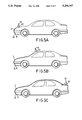
- the hook members 51 are first hooked on the front bottom of the automobile, as shown in FIG. 5A.
- the wheels 40 are disposed on the external surface of the automobile and are moved rearwardly from along the top portion of the automobile by carrying the handle 16 therealong, as best illustrated in FIGS. 5A and 5B. Therefore, the cover cloth 3 can be easily and rapidly applied to the automobile without applying a great pulling force.
- the wheels 40 are provided with cushion pads 44, and because there is no relative movement of the cover cloth 3 and the external surface of the automobile, the baked paint of the automobile will not be damaged when the automobile covering device of this invention is moved along the automobile.
- the cover cloth 3 may be rewound back into the cylindrical member 1 by means of the restoring force of the spiral torsional springs 21 when the automobile covering device is moved frontward in order to uncover the automobile.
Landscapes
- Engineering & Computer Science (AREA)
- Mechanical Engineering (AREA)
- Packaging Of Machine Parts And Wound Products (AREA)
Abstract
An automobile covering device includes a hollow cylindrical member having two closed ends, an axial slot and a water outlet. A U-shaped handle has two ends connected pivotally to the two closed ends of the cylindrical member. A cylinder with an axial shaft is received coaxially and rotatably in the cylindrical member. The axial shaft has two free ends which pass through the two closed ends of the cylindrical member, respectively. Two spiral torsional springs are respectively mounted on the two closed ends of the cylindrical member. Each of the spiral torsional springs has a first end connected to one of the free ends of the axial shaft and a second end connected to one of the closed ends of the cylindrical member. A roll of cover cloth is wound on the cylinder and has a pull end passing through the axial slot of the cylindrical member. Two rollers are rotatably mounted on the two closed ends of the cylindrical member, respectively. A fastening device is provided for fastening the pull end of the cover cloth and the cylindrical member on an automobile.
Description
1. Field of the Invention
This invention relates to an automobile covering device, more particularly to an automobile covering device in which a cover cloth can be easily applied to the automobile.
2. Description of the Related Art
FIG. 1 shows a conventional automobile covering device which includes a base frame (A) having an automatically winding device (B) mounted rotatably therein. The automatically winding device (B) has a roll of cover cloth (D) wound thereon. A fastening device (C) includes a rope member, two hooks (C2) provided on the base frame (A) and a hook rod (C3) provided on a pull end of the cover cloth (D). In use, the rope member is tied on the trunk lid of the automobile, as illustrated in FIG. 2A. The rope member and the hooks (C2) are hooked on the rear bottom of the automobile, as illustrated in FIG. 2B. The cover cloth (D) is then pulled over the automobile from the rear to the front of the automobile in order to cover the automobile, as illustrated in FIGS. 2C and 2D. However, when the cover cloth (D) is pulled over the automobile, a great friction force between the cover cloth (D) and the external surface of the automobile is produced. Therefore, pulling the cover cloth is a relatively strenuous work. In addition, the paint on the external surface of the automobile is liable to be damaged when a user drags the cover cloth (D) in order to overcome said friction force.
It is therefore a main object of this invention to provide an automobile covering device which can be used to cover the automobile easily.
It is another object of this invention to provide an automobile covering device which will not damage the paint of the automobile.
Accordingly, the automobile covering device of this invention comprises:
a hollow cylindrical member having two closed ends, an axial slot and a water outlet formed therein;
a U-shaped handle having two ends connected pivotally to the two closed ends of the cylindrical member;
a cylinder with an axial shaft coaxially and received rotatably in the cylindrical member, the axial shaft having two free ends passing through the two closed ends of the cylindrical member, respectively;
two spiral torsional springs mounted respectively on the two closed ends of the cylindrical member, each of the spiral torsional springs having a first end connected to one of the free ends of the axial shaft and a second end connected to one of the closed ends of the cylindrical member;
two caps mounted detachably on the two closed ends of the cylindrical member so as to cover the spiral springs;
a roll of cover cloth wound on the cylinder, the cover cloth having a pull end passing through the axial slot of the cylindrical member;
two rollers mounted rotatably to the two closed ends of the cylindrical member, respectively; and
a fastening means for fastening the pull end of the cover cloth and the cylindrical member on an automobile.
Other features and advantages of this invention will become apparent in the following detailed description of the preferred embodiment of this invention with reference to the accompanying drawings.
FIG. 1 is a perspective view of a conventional automobile covering device;
FIGS. 2A to 2D are perspective schematic views illustrating the conventional automobile covering device when in use;
FIG. 3 is a perspective exploded view of a preferred embodiment of an automobile covering device of this invention;
FIG. 3A is an enlarged plan view of the periphery of one of the closed ends of a hollow cylindrical member of this invention;
FIG. 3B is an enlarged plan view of a bearing mounted to the closed ends of the hollow cylindrical member of this invention;
FIG. 4 is a perspective schematic view of the preferred embodiment of an automobile covering device of this invention when in use; and
FIG. 5A to 5C are plan schematic views illustrating the automobile covering device of this invention when being used.
FIGS. 3 and 4 show a preferred embodiment of an automobile covering device of this invention. The automobile covering device includes a hollow cylindrical member 1 which is formed of two semi-cylindrical parts, 101 and 102, with two closed ends, 11 and 12. The two closed ends, 11 and 12, are fixed by internal end grooves 1011 of the two semi-cylindrical parts, 101 and 102. The hollow cylindrical member 1 has two external end grooves (T) formed after the two semi-cylindrical parts, 101 and 102, are combined, as best illustrated in FIG. 3A. An axial slot 13 and a water outlet 14 are formed oppositely in the cylindrical member 1, as shown in FIG. 4. The water outlet 14 allows rain water to flow out of the hollow cylindrical member 1. Two lugs 15 are respectively provided at the peripheries of the two closed ends, 11 and 12. A U-shaped handle 16 has two ends connected pivotally to the two lugs 15 of the cylindrical member 1. Two ring members, 111 and 112, are respectively formed on the external faces of the two closed ends, 11 and 12.
A cylinder 20 with an axial shaft 201 is received coaxially and rotatably in the cylindrical member 1. The axial shaft 201 has two free ends passing through the two closed ends, 11 and 12, of the cylindrical member 1, respectively. Two roll bearings 42 are respectively mounted between the two ends of the cylinder 20 and the free ends 201 of the two closed ends, 11 and 12, of the cylindrical member 1.
Two spiral torsional springs 21 are respectively received in the ring members, 111 and 121, of the two closed ends 11 and 12. Each of the spiral torsional springs 21 has a first end 211 connected to one of the free ends of the axial shaft 201 and a second end 212 connected to one of the ring members, 111 and 121, of the closed ends, 11 and 12, of the cylindrical member 1.
Two caps 22 are mounted detachably on the two ring members, 111 and 121, so as to cover the spiral springs 21. Each outside face of the caps 22 has a cylindrical projection 221 formed axially thereon. Each of the cylindrical projections 221 has an internal threaded hole formed therein.
A roll of cover cloth 3 is wound on the cylinder 20. The cover cloth 3 has a pull end 31 which passes through the axial slot 13 of the cylindrical member 1. A rod 32 is attached to the pull end 31 of the cover cloth 3. Therefore, the cover cloth 3 can be pulled out by means of pulling the rod 32 away from the cylindrical member 1, as best illustrated by the phantom lines in FIG. 4.
Two rollers 4 are mounted rotatably on the two closed ends, 11 and 12, of the cylindrical member 1, respectively. Each of the rollers 4 includes a wheel 40 and a bearing 41 mounted between the wheel 40 and one of the closed ends, 11 and 12, of the cylindrical member 1. The bearing 41 is a teflon ring having a plurality of rolling balls 412 provided therearound. Each of the wheels 40 has a cushion pad 44 provided therearound and a central hole 401 formed therein. The cylindrical projections 221 pass respectively through the central holes 401 of the wheels 40 and engage two threaded bolts 43 such that the wheels 40 can be rotated about the cylindrical projections 221 of the caps 22.
A rope member 50 is provided on the handle, 16 and two hook members are provided on the pull end 31 of the cover cloth 3 in order to fasten the pull end 31 of the cover cloth 3 and the cylindrical member 1 on the front and rear of an automobile.
In use, the hook members 51 are first hooked on the front bottom of the automobile, as shown in FIG. 5A. The wheels 40 are disposed on the external surface of the automobile and are moved rearwardly from along the top portion of the automobile by carrying the handle 16 therealong, as best illustrated in FIGS. 5A and 5B. Therefore, the cover cloth 3 can be easily and rapidly applied to the automobile without applying a great pulling force. In addition, because the wheels 40 are provided with cushion pads 44, and because there is no relative movement of the cover cloth 3 and the external surface of the automobile, the baked paint of the automobile will not be damaged when the automobile covering device of this invention is moved along the automobile. In reverse, the cover cloth 3 may be rewound back into the cylindrical member 1 by means of the restoring force of the spiral torsional springs 21 when the automobile covering device is moved frontward in order to uncover the automobile.
With this invention thus explained, it is apparent that numerous modifications and variations can be made without departing from the scope and spirit of this invention. It is therefore intended that this invention be limited only as indicated in the appended claims.
Claims (7)
1. An automobile covering device comprising:
a hollow cylindrical member having two closed ends, an axial slot and a water outlet formed therein;
a U-shaped handle having two ends connected pivotally to said two closed ends of said cylindrical member;
a cylinder with an axial shaft received coaxially and rotatably in said cylindrical member, said axial shaft having two free ends passing through said two closed ends of said cylindrical member, respectively;
two spiral torsional springs mounted respectively on said two closed ends of said cylindrical member, each of said spiral torsional springs having a first end connected to one of said free ends of said axial shaft and a second end connected to one of said closed ends of said cylindrical member;
two caps mounted detachably on said two closed ends of said cylindrical member so as to cover said spiral springs;
a roll of cover cloth wound on said cylinder, said cover cloth having a pull end passing through said axial slot of said cylindrical member;
two rollers mounted rotatably on said two closed ends of said cylindrical member, respectively; and
means for fastening said pull end of said cover cloth and said cylindrical member on an automobile.
2. An automobile covering device as claimed in claim 1, wherein each of said rollers includes a wheel and a bearing mounted between said wheel and one of said closed ends of said cylindrical member.
3. An automobile covering device as claimed in claim 2, wherein said bearing is a teflon ring having a plurality of rolling balls provided therearound.
4. An automobile covering device as claimed in claim 1, further comprising two roll bearings mounted between said closed ends of said cylindrical member and said free ends of said axial shaft of said cylinder.
5. An automobile covering device as claimed in claim 4, wherein said cylindrical member is made of two semi-cylindrical parts.
6. An automobile covering device as claimed in claim 5, wherein said fastening means includes a rope member provided on said handle and two hook members provided on said pull end of said cover cloth.
7. An automobile covering device as claimed in claim 6, wherein each of said wheels has a cushion pad provided therearound.
Priority Applications (1)
| Application Number | Priority Date | Filing Date | Title |
|---|---|---|---|
| US07/986,981 US5294167A (en) | 1992-12-08 | 1992-12-08 | Automobile covering device |
Applications Claiming Priority (1)
| Application Number | Priority Date | Filing Date | Title |
|---|---|---|---|
| US07/986,981 US5294167A (en) | 1992-12-08 | 1992-12-08 | Automobile covering device |
Publications (1)
| Publication Number | Publication Date |
|---|---|
| US5294167A true US5294167A (en) | 1994-03-15 |
Family
ID=25532956
Family Applications (1)
| Application Number | Title | Priority Date | Filing Date |
|---|---|---|---|
| US07/986,981 Expired - Fee Related US5294167A (en) | 1992-12-08 | 1992-12-08 | Automobile covering device |
Country Status (1)
| Country | Link |
|---|---|
| US (1) | US5294167A (en) |
Cited By (24)
| Publication number | Priority date | Publication date | Assignee | Title |
|---|---|---|---|---|
| US5409286A (en) * | 1993-12-14 | 1995-04-25 | Huang; Robert I. | Protective cover for automobile |
| US5615725A (en) * | 1995-12-14 | 1997-04-01 | Formosa Saint Jose Corp. | Outdoor sun shade |
| US5855406A (en) * | 1997-04-24 | 1999-01-05 | Vargo; Eric A. | Storage and deployment system for automobile covers |
| US6059010A (en) * | 1999-07-15 | 2000-05-09 | Formosa Saint Jose Corporation | Roller sunshade for mounting on car roof |
| US6092857A (en) * | 1998-06-11 | 2000-07-25 | Rivas; Lawrence E. | Anchorable vehicle cover |
| US6112460A (en) * | 1998-10-23 | 2000-09-05 | Evenflo Company, Inc. | Walk-through gate with top rail support |
| US6131643A (en) * | 1998-11-17 | 2000-10-17 | New Century Sci & Tech, Inc. | Sun shield device for parked automobile |
| US6178694B1 (en) | 1998-10-23 | 2001-01-30 | Evenflo Company, Inc. | Walk-through gate with concealed hinge and latch |
| US6502889B2 (en) * | 1999-04-16 | 2003-01-07 | Yoshiharu Fukagawa | Body cover device for car |
| US20040178117A1 (en) * | 2003-03-11 | 2004-09-16 | Morton Robert W. | Desulfurization and novel compositions for same |
| US20040178618A1 (en) * | 2003-03-12 | 2004-09-16 | Rhea Thomas C. | Automated covering for an automobile |
| US20040238089A1 (en) * | 2003-05-28 | 2004-12-02 | Xingkang Li | Self coiling roll-up car cover |
| CN100339246C (en) * | 2004-09-21 | 2007-09-26 | 王可力 | Automatic folding automobile protective cover |
| GB2450500A (en) * | 2007-06-26 | 2008-12-31 | Moshe Buhbut | Vehicle cover assembly having motor-assisted winding and unwinding of cover |
| US20090065629A1 (en) * | 2007-09-06 | 2009-03-12 | Veit Kenneth C | Personal portable tissue roll holder |
| US20100307700A1 (en) * | 2009-06-06 | 2010-12-09 | Tsung-Hsiang Wang | Fabric gate |
| US7862100B1 (en) * | 2009-05-15 | 2011-01-04 | Smith Stanford E | Motorcycle seat covering system |
| US20130220865A1 (en) * | 2012-02-28 | 2013-08-29 | Hon Hai Precision Industry Co., Ltd. | Protection case for electronic device |
| CN106394209A (en) * | 2016-10-21 | 2017-02-15 | 河南科技大学 | Anti-hail device for automobile |
| US9636976B2 (en) | 2014-09-15 | 2017-05-02 | Kcrof Enterprises, LLC | Soft window storage unit and method |
| US9925855B2 (en) * | 2015-01-14 | 2018-03-27 | Raymond Anthony Joao | Cover apparatus and method for vehicle windows and/or other vehicle components |
| CN108995515A (en) * | 2018-09-03 | 2018-12-14 | 何滔 | A kind of Novel automobile covering storage device |
| US20230287688A1 (en) * | 2022-03-11 | 2023-09-14 | Roswell Canada Inc. | Self-coiling apparatus |
| US12494738B2 (en) | 2022-10-27 | 2025-12-09 | Babak CYRUS | Vehicle solar charging system |
Citations (3)
| Publication number | Priority date | Publication date | Assignee | Title |
|---|---|---|---|---|
| FR1074987A (en) * | 1953-02-23 | 1954-10-11 | Improvements to car protection devices against bad weather | |
| US3680807A (en) * | 1969-04-02 | 1972-08-01 | Warren D Fortson | Wire stringing rig |
| US4718711A (en) * | 1986-08-08 | 1988-01-12 | David Rabbit | Portable car port |
-
1992
- 1992-12-08 US US07/986,981 patent/US5294167A/en not_active Expired - Fee Related
Patent Citations (3)
| Publication number | Priority date | Publication date | Assignee | Title |
|---|---|---|---|---|
| FR1074987A (en) * | 1953-02-23 | 1954-10-11 | Improvements to car protection devices against bad weather | |
| US3680807A (en) * | 1969-04-02 | 1972-08-01 | Warren D Fortson | Wire stringing rig |
| US4718711A (en) * | 1986-08-08 | 1988-01-12 | David Rabbit | Portable car port |
Cited By (33)
| Publication number | Priority date | Publication date | Assignee | Title |
|---|---|---|---|---|
| US5409286A (en) * | 1993-12-14 | 1995-04-25 | Huang; Robert I. | Protective cover for automobile |
| US5615725A (en) * | 1995-12-14 | 1997-04-01 | Formosa Saint Jose Corp. | Outdoor sun shade |
| US5855406A (en) * | 1997-04-24 | 1999-01-05 | Vargo; Eric A. | Storage and deployment system for automobile covers |
| US6092857A (en) * | 1998-06-11 | 2000-07-25 | Rivas; Lawrence E. | Anchorable vehicle cover |
| US6178694B1 (en) | 1998-10-23 | 2001-01-30 | Evenflo Company, Inc. | Walk-through gate with concealed hinge and latch |
| US6112460A (en) * | 1998-10-23 | 2000-09-05 | Evenflo Company, Inc. | Walk-through gate with top rail support |
| US6131643A (en) * | 1998-11-17 | 2000-10-17 | New Century Sci & Tech, Inc. | Sun shield device for parked automobile |
| US6502889B2 (en) * | 1999-04-16 | 2003-01-07 | Yoshiharu Fukagawa | Body cover device for car |
| US6059010A (en) * | 1999-07-15 | 2000-05-09 | Formosa Saint Jose Corporation | Roller sunshade for mounting on car roof |
| US20040178117A1 (en) * | 2003-03-11 | 2004-09-16 | Morton Robert W. | Desulfurization and novel compositions for same |
| US20040178618A1 (en) * | 2003-03-12 | 2004-09-16 | Rhea Thomas C. | Automated covering for an automobile |
| US20050127710A1 (en) * | 2003-03-12 | 2005-06-16 | Rhea Thomas C. | Automated covering for an automobile |
| US6916043B2 (en) | 2003-03-12 | 2005-07-12 | Thomas C. Rhea | Automated covering for an automobile |
| US7008002B2 (en) * | 2003-03-12 | 2006-03-07 | Thomas C. Rhea | Automated covering for an automobile |
| US20040238089A1 (en) * | 2003-05-28 | 2004-12-02 | Xingkang Li | Self coiling roll-up car cover |
| CN100339246C (en) * | 2004-09-21 | 2007-09-26 | 王可力 | Automatic folding automobile protective cover |
| GB2450500A (en) * | 2007-06-26 | 2008-12-31 | Moshe Buhbut | Vehicle cover assembly having motor-assisted winding and unwinding of cover |
| US20090065629A1 (en) * | 2007-09-06 | 2009-03-12 | Veit Kenneth C | Personal portable tissue roll holder |
| US7862100B1 (en) * | 2009-05-15 | 2011-01-04 | Smith Stanford E | Motorcycle seat covering system |
| US20100307700A1 (en) * | 2009-06-06 | 2010-12-09 | Tsung-Hsiang Wang | Fabric gate |
| US8191604B2 (en) * | 2009-06-06 | 2012-06-05 | Tsung-Hsiang Wang | Fabric gate |
| US20130220865A1 (en) * | 2012-02-28 | 2013-08-29 | Hon Hai Precision Industry Co., Ltd. | Protection case for electronic device |
| US9056707B2 (en) * | 2012-02-28 | 2015-06-16 | Fu Tai Hua Industry (Shenzhen) Co., Ltd. | Protection case for electronic device |
| US9636976B2 (en) | 2014-09-15 | 2017-05-02 | Kcrof Enterprises, LLC | Soft window storage unit and method |
| US9925855B2 (en) * | 2015-01-14 | 2018-03-27 | Raymond Anthony Joao | Cover apparatus and method for vehicle windows and/or other vehicle components |
| US10207571B2 (en) * | 2015-01-14 | 2019-02-19 | Raymond Anthony Joao | Cover apparatus and method for vehicle windows and/or other vehicle components |
| US20190135098A1 (en) * | 2015-01-14 | 2019-05-09 | Raymond Anthony Joao | Cover apparatus and method for vehicle windows and/or other vehicle components |
| US10618396B2 (en) * | 2015-01-14 | 2020-04-14 | Raymond Anthony Joao | Cover apparatus and method for vehicle windows and/or other vehicle components |
| CN106394209A (en) * | 2016-10-21 | 2017-02-15 | 河南科技大学 | Anti-hail device for automobile |
| CN108995515A (en) * | 2018-09-03 | 2018-12-14 | 何滔 | A kind of Novel automobile covering storage device |
| US20230287688A1 (en) * | 2022-03-11 | 2023-09-14 | Roswell Canada Inc. | Self-coiling apparatus |
| US12607017B2 (en) * | 2022-03-11 | 2026-04-21 | Roswell Canada Inc. | Self-coiling apparatus |
| US12494738B2 (en) | 2022-10-27 | 2025-12-09 | Babak CYRUS | Vehicle solar charging system |
Similar Documents
| Publication | Publication Date | Title |
|---|---|---|
| US5294167A (en) | Automobile covering device | |
| US5355980A (en) | Suitcase with extensible handle and foldable plate for carrying another suitcase thereon | |
| FR2844457A3 (en) | Rowing simulator for physical exercise has variable load and adjustable physical range | |
| US4407027A (en) | Pool-cover apparatus and method | |
| US5957400A (en) | Self winding hose reel | |
| US5020792A (en) | Exercise bicycle for exercising arms and legs | |
| US5016726A (en) | Self-propulsion device for skateboards or the like | |
| BE1003952A6 (en) | Distributeu r. | |
| US6916143B2 (en) | Speed handle for winch | |
| US5333808A (en) | Wire unreeling device | |
| US5762079A (en) | Portable floss dispensing system | |
| US5520212A (en) | Self winding hose reel | |
| US3128962A (en) | figures | |
| US5669574A (en) | Storable carpet runner | |
| US20030085392A1 (en) | Hand operated cable dragging machine | |
| JP3778306B2 (en) | Carrying tool | |
| US5518023A (en) | Hose coiling apparatus | |
| EP1251021B1 (en) | Curtain with coiled spring | |
| US2791270A (en) | Tread compressing type tire bead seating device | |
| JPS6141652Y2 (en) | ||
| US5938139A (en) | Manually operated screen reeling device | |
| JPH0318460Y2 (en) | ||
| JPH0453790U (en) | ||
| JP2531959Y2 (en) | Roll screen | |
| JPH0125191Y2 (en) |
Legal Events
| Date | Code | Title | Description |
|---|---|---|---|
| FEPP | Fee payment procedure |
Free format text: PAYOR NUMBER ASSIGNED (ORIGINAL EVENT CODE: ASPN); ENTITY STATUS OF PATENT OWNER: SMALL ENTITY |
|
| FPAY | Fee payment |
Year of fee payment: 4 |
|
| REMI | Maintenance fee reminder mailed | ||
| LAPS | Lapse for failure to pay maintenance fees | ||
| STCH | Information on status: patent discontinuation |
Free format text: PATENT EXPIRED DUE TO NONPAYMENT OF MAINTENANCE FEES UNDER 37 CFR 1.362 |
|
| FP | Lapsed due to failure to pay maintenance fee |
Effective date: 20020315 |