US528585A - Combination-lock - Google Patents
Combination-lock Download PDFInfo
- Publication number
- US528585A US528585A US528585DA US528585A US 528585 A US528585 A US 528585A US 528585D A US528585D A US 528585DA US 528585 A US528585 A US 528585A
- Authority
- US
- United States
- Prior art keywords
- plate
- bolt
- ribs
- spindle
- notch
- Prior art date
- Legal status (The legal status is an assumption and is not a legal conclusion. Google has not performed a legal analysis and makes no representation as to the accuracy of the status listed.)
- Expired - Lifetime
Links
Images
Classifications
-
- E—FIXED CONSTRUCTIONS
- E05—LOCKS; KEYS; WINDOW OR DOOR FITTINGS; SAFES
- E05B—LOCKS; ACCESSORIES THEREFOR; HANDCUFFS
- E05B37/00—Permutation or combination locks; Puzzle locks
- E05B37/12—Permutation or combination locks; Puzzle locks with tumbler discs on several axes
-
- Y—GENERAL TAGGING OF NEW TECHNOLOGICAL DEVELOPMENTS; GENERAL TAGGING OF CROSS-SECTIONAL TECHNOLOGIES SPANNING OVER SEVERAL SECTIONS OF THE IPC; TECHNICAL SUBJECTS COVERED BY FORMER USPC CROSS-REFERENCE ART COLLECTIONS [XRACs] AND DIGESTS
- Y10—TECHNICAL SUBJECTS COVERED BY FORMER USPC
- Y10T—TECHNICAL SUBJECTS COVERED BY FORMER US CLASSIFICATION
- Y10T70/00—Locks
- Y10T70/70—Operating mechanism
- Y10T70/7153—Combination
- Y10T70/7181—Tumbler type
- Y10T70/7198—Single tumbler set
- Y10T70/7237—Rotary or swinging tumblers
- Y10T70/726—Individually set
Definitions
- This invention relates to looks, and more especially to that class thereof known as permutation locks; and the object of the same is to effect certain improvements in the construction thereof.
- Fig. 2 is a rear elevation thereof with part of the casing broken away, the bolt being shown as shot.
- Fig. 3 is a rear elevation with all of the back plate of the casing removed, the bolt being shown as retracted.
- Fig. 4 is a horizontal section of Fig. 3, taken just beneath the top plate of the casing.
- Fig. 5 is an enlarged section through the spindle of one tu inbler.
- Fig. 6 is a section on the line 66 of Fig. 5
- Figs. 7 and 8 are reduced front elevations illustrating modifications.
- Fig. 9 is a plan view of the locking knob and spindle.
- Fig. 10 is a partial end view of the bolt and locking plate.
- Fig. 11 is a sectional detail showing the ribs on the flange of the locking plate.
- the numeral 1 designates the face plate carrying at its rear side a casing 12 containing the lock mechanism as usual and having an opening 13 through which the bolt 4 projects.
- Said bolt slides horizontally between the parallel inner faces of rectangular posts or guides 5 which connect the face plate 1 with the back plate of the casing, and the bolt has in its upper edge two notches 4 and 4 for a purpose to appear below, and in its lower edge a notch 4 for the bit of the locking spindle as will also be described below. 4
- the numeral 6 designates a locking plate which stands in rear of the bolt and has notches 8 in its upper edge which are rectangular so as to fit around the posts 5 and sufficiently deep to permit the plate to have a sliding vertical movement. Depending from the lower edge of this plate are tongues 7 which slide against the outer faces 5 of the lowermost posts 5, whereas the bolt 4 slides upon the upper flat faces 5 of said posts.
- a forwardly projecting flange 6 which passes over the upper edge of the bolt and is provided at a proper point with a depending rib 6 of a size to fall into one of the notches 4 or l
- This flange is also provided on its upper face with ribs 6 for a purpose to appear below.
- the numerals 2 designate knobs or buttons having scales marked on their faces which move over indicating marks 1 as seen in Fig. 1, although obviously the scale could be on the face plate and the indicating mark on the button.
- the spindle 2* of each knob (see Fig.
- a notch 9 of a size adapted to receive the top rib 6 of the locking plate when properly turned as seen in Fig. 3.
- knob spindles and tumblers are similarly constructed, and hence before the locking plate can be raised to lift its depending rib 6 out of one of the notches in the bolt,
- the numeral 3 designates the locking knob 5 which is preferably of a size and shape to correspond with the tumbler knobs 2, though simply for the sake of confusing an unauthorized person.
- the spindle 3 of this knob has two holes 3 and 3 in which are respectively seated to a long bit 3 and a short bit 3", the former working in the notch 4 at the lower side of the bolt, and the latter working against the lower edge of the looking plate and in opposition to the power of a spring 14.- which presses r 5 said plate normally downward.
- the knobs 2 are first turned to bring all the notches 9 in the tumblers over the top ribs 6 of the locking plate, and to do this one must, of course, know the proper combination.
- the knob 3 is then turned to the right as seen in Fig. 2, and the first motion causes the short bit 3 to lift the locking plate in its guides so as to pass its top ribs 6 into the notches 9 and to raise its depending ribs 6 out of the notch 4. in the bolt, and a continued rotation of the spindle 3 causes the long bit 3 to strike the right wall of the notch 4 in the bolt and retract the latter to the position shown in Fig. 3.
- the last motion of the spindle 3 passes the short bit 3 out from under the locking plate and allows it to descend, so that the depending rib 6 enters the notch at in the bolt and fastens the latter in unlocked 5 position.
Landscapes
- Connection Of Plates (AREA)
Description
(No Model.)
H. BARDITZKY.-
COMBINATION LOOK.
Patented Nov. 6
. l. Fhwiitf.
1 Noam PETERS o0 Puma-um NITED STATES ATENT Orrrcn.
COMBINATION-LOCK.
SPECIFICATION forming part of Letters Patent No. 528,585, dated November 6, 1894. Application filed May 1, 1394. Serial No. 509,626. (No model.)
To all whom it may concern:
l 3e it known that I, HERMAN BARDITZKY, a citizen of the United States, residing atFlorence, 1n the county of Lauderdale and State of Alabama, have invented certain new and useful Improvements in Oombination-Locksg and I do hereby declare the following to be a full, clear, and exact description of the invention, such as will enable others skilled in the art to which it appertains to make and use the same.
This invention relates to looks, and more especially to that class thereof known as permutation locks; and the object of the same is to effect certain improvements in the construction thereof.
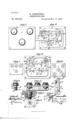
To this end the invention consists in the specific details of construction hereinafter more fully described and claimed, and as illustrated in the drawings, wherein- Figure 1 is a front elevation of this look.
Fig. 2 is a rear elevation thereof with part of the casing broken away, the bolt being shown as shot. Fig. 3 is a rear elevation with all of the back plate of the casing removed, the bolt being shown as retracted. Fig. 4 is a horizontal section of Fig. 3, taken just beneath the top plate of the casing. Fig. 5 is an enlarged section through the spindle of one tu inbler. Fig. 6 is a section on the line 66 of Fig. 5 Figs. 7 and 8 are reduced front elevations illustrating modifications. Fig. 9 is a plan view of the locking knob and spindle. Fig. 10 is a partial end view of the bolt and locking plate. Fig. 11 is a sectional detail showing the ribs on the flange of the locking plate.
In the said drawings, the numeral 1 designates the face plate carrying at its rear side a casing 12 containing the lock mechanism as usual and having an opening 13 through which the bolt 4 projects. Said bolt slides horizontally between the parallel inner faces of rectangular posts or guides 5 which connect the face plate 1 with the back plate of the casing, and the bolt has in its upper edge two notches 4 and 4 for a purpose to appear below, and in its lower edge a notch 4 for the bit of the locking spindle as will also be described below. 4
The numeral 6 designates a locking plate which stands in rear of the bolt and has notches 8 in its upper edge which are rectangular so as to fit around the posts 5 and sufficiently deep to permit the plate to have a sliding vertical movement. Depending from the lower edge of this plate are tongues 7 which slide against the outer faces 5 of the lowermost posts 5, whereas the bolt 4 slides upon the upper flat faces 5 of said posts. At the upper edge of the plate 6 is a forwardly projecting flange 6 which passes over the upper edge of the bolt and is provided at a proper point with a depending rib 6 of a size to fall into one of the notches 4 or l This flange is also provided on its upper face with ribs 6 for a purpose to appear below. In Figs. 1, 2, and 3, two of these top ribs 6 are shown. In Fig. 7 it will be understood that there must be three of these ribs; while in Fig. 8 there are two top ribs and the tongues 7 are continued down around and beneath the lowermost tumblers and carry additional upwardly projecting'ribs 6 and the purpose of-all these ribs will appear below.
The numerals 2 designate knobs or buttons having scales marked on their faces which move over indicating marks 1 as seen in Fig. 1, although obviously the scale could be on the face plate and the indicating mark on the button. The spindle 2* of each knob (see Fig. 5) has a bearing 2 in the face plate 1, inside of which it is reduced and made polygonal as seen at 2, and inside of this it is further reduced as at 2 and provided with threads 2 9 is a disk shaped tumbler having a polygonal hole 9 through its center of a size to be passed onto the polygonal portion 2 of the spindle, and the number of faces in this polygonal .hole preferably correspond with the numbers on the knob in order that the com bination of the lock may be changed in a manner which will be clear. Such change is permitted by a nut 10 which screws onto the threads 2 and clamps a washer 11 against the tumbler 9 and the latter against the cylindrical bearing 2 as will be clear. In the edge of the tumbler is a notch 9 of a size adapted to receive the top rib 6 of the locking plate when properly turned as seen in Fig. 3.
All the knob spindles and tumblers are similarly constructed, and hence before the locking plate can be raised to lift its depending rib 6 out of one of the notches in the bolt,
ICO
all of the notches 9 must be caused to stand directly over the top ribs 6 (and 6 in Fig.8) of the locking plate.
The numeral 3 designates the locking knob 5 which is preferably of a size and shape to correspond with the tumbler knobs 2, though simply for the sake of confusing an unauthorized person. The spindle 3 of this knob has two holes 3 and 3 in which are respectively seated to a long bit 3 and a short bit 3", the former working in the notch 4 at the lower side of the bolt, and the latter working against the lower edge of the looking plate and in opposition to the power of a spring 14.- which presses r 5 said plate normally downward.
In operation, the parts standing as in Fig. 2, the knobs 2 are first turned to bring all the notches 9 in the tumblers over the top ribs 6 of the locking plate, and to do this one must, of course, know the proper combination. The knob 3 is then turned to the right as seen in Fig. 2, and the first motion causes the short bit 3 to lift the locking plate in its guides so as to pass its top ribs 6 into the notches 9 and to raise its depending ribs 6 out of the notch 4. in the bolt, and a continued rotation of the spindle 3 causes the long bit 3 to strike the right wall of the notch 4 in the bolt and retract the latter to the position shown in Fig. 3. The last motion of the spindle 3 passes the short bit 3 out from under the locking plate and allows it to descend, so that the depending rib 6 enters the notch at in the bolt and fastens the latter in unlocked 5 position. I
All parts of this machine are of the desired sizes, shapes, proportions, and materials, and
additional rib at the center of the length of the flange 6. For the construction shown in Fig.8 some arms must depend from the plate and pass under the lowermost tumblers so as to carry additional top ribs G as indicated in dotted lines in this view.
What is claimed as new is In a permutation lock, the combination with the casing having square posts forming guides, and a bolt sliding between the horizontal faces of said guides and provided with a notch in its upper edge and one in its lower edge; of a locking plate sliding vertically against upright faces of said guides, a depending rib on said plate adapted to enter the notch in the upper edge of the bolt when the latter is shot, arms depending from the plate near its ends and having top ribs 6*, a spring bearing the plate norm ally downward, notched tumblers located above and below the bolt for engaging all said top ribs and preventing the rising of said plate, and a spindle having a bit for raising the plate and entering said lower notch in the bolt for moving the latter, as and for the purpose set forth.
In testimony whereof Iaffix my signaturein presence of two witnesses.
HERMAN BARDITZKY.
\Vitnesses:
R. T. SIMPSON, J r., LOUIS LEONI.
Publications (1)
| Publication Number | Publication Date |
|---|---|
| US528585A true US528585A (en) | 1894-11-06 |
Family
ID=2597371
Family Applications (1)
| Application Number | Title | Priority Date | Filing Date |
|---|---|---|---|
| US528585D Expired - Lifetime US528585A (en) | Combination-lock |
Country Status (1)
| Country | Link |
|---|---|
| US (1) | US528585A (en) |
-
0
- US US528585D patent/US528585A/en not_active Expired - Lifetime
Similar Documents
| Publication | Publication Date | Title |
|---|---|---|
| US526740A (en) | rapaport | |
| US528585A (en) | Combination-lock | |
| US600368A (en) | Knob attachment | |
| US126074A (en) | Improvement in permutation locks | |
| US551296A (en) | James william tatum | |
| US129482A (en) | Improvement in combination locks | |
| US589844A (en) | Permutation-lock | |
| US270114A (en) | Per mutation-lock | |
| US552277A (en) | Permutation-pad lock | |
| US525615A (en) | Andrew o keefe | |
| US176876A (en) | Improvement in combination-locks | |
| US3221A (en) | Lqck fob | |
| US596164A (en) | Combination-lock | |
| US599596A (en) | Henry bruck | |
| US374712A (en) | Permutation-lock | |
| US345270A (en) | Permutation-lock | |
| US453238A (en) | Perm utation-lock | |
| US146191A (en) | Improvement in permutation-locks | |
| US820557A (en) | Combination-lock. | |
| US447621A (en) | phillips | |
| US180758A (en) | Improvement in combination-locks | |
| US401540A (en) | Peters | |
| US427411A (en) | Alarm-lock | |
| US116737A (en) | Improvement in permutation locks | |
| US170586A (en) | Improvement in sash-holders |