US525934A - Boot tkee - Google Patents
Boot tkee Download PDFInfo
- Publication number
- US525934A US525934A US525934DA US525934A US 525934 A US525934 A US 525934A US 525934D A US525934D A US 525934DA US 525934 A US525934 A US 525934A
- Authority
- US
- United States
- Prior art keywords
- boot
- toe
- tree
- heel
- thrust rod
- Prior art date
- Legal status (The legal status is an assumption and is not a legal conclusion. Google has not performed a legal analysis and makes no representation as to the accuracy of the status listed.)
- Expired - Lifetime
Links
- 238000012856 packing Methods 0.000 description 3
- 239000002184 metal Substances 0.000 description 2
- 150000001875 compounds Chemical class 0.000 description 1
- 230000000994 depressogenic effect Effects 0.000 description 1
- 230000000694 effects Effects 0.000 description 1
- 238000005058 metal casting Methods 0.000 description 1
- 230000002035 prolonged effect Effects 0.000 description 1
- 230000003014 reinforcing effect Effects 0.000 description 1
- 238000009423 ventilation Methods 0.000 description 1
Images

Classifications
-
- A—HUMAN NECESSITIES
- A43—FOOTWEAR
- A43D—MACHINES, TOOLS, EQUIPMENT OR METHODS FOR MANUFACTURING OR REPAIRING FOOTWEAR
- A43D3/00—Lasts
- A43D3/14—Stretching or spreading lasts; Boot-trees; Fillers; Devices for maintaining the shape of the shoe
- A43D3/1433—Shoe-trees
- A43D3/1466—Shoe-trees stretching the length of a shoe, i.e. longitudinally expandable
- A43D3/1475—Shoe-trees stretching the length of a shoe, i.e. longitudinally expandable adjustable
Definitions
- My improvement in boot trees has for its object to render the action of the boot tree more efficient by so applying the pressure as to produce an upward thrust against the front of the upper near the instep and to produce a tree which is lighter, less bulky, more easily applied and adjusted, and capable of being packed away into a smaller compass than other trees now in use.
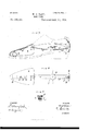
- the invention consists in the combination, witha front or too portion and a rear or heel portion, of an intermediate adjustable thrust rod jointed to the front and heel portions and adapted to act as a toggle and to apply pressure to the front or too portion in the manner hereinafterdescribed with reference to the accompanying drawings, forming part of this specification, wherein- Figure 1 is a side elevation and Fig. 2 a plan of one arrangement of tree, the shoe to which it is applied being represented in dotted lines in Fig. 1.
- Fig. 3 is a side elevation, Fig. 4., a plan, and Fig. 5 a cross-section on line 1-1, Fig. 4, of another arrangement of boot tree, the shoe to which it is applied be- 4 ing represented in dotted lines in Fig. 3.
- the front or toe portion A is a metal casting or sheet metal stamping, of concavo-oonvex form in cross-section conforming in shape and configuration to the shape of the fore partof the boot and extending from the toe toward the instep the necessary distance to preserve the front of the boot in shape.
- This /front or too portion A takes a downward bearing on the sole at or near its toe extremity so as to form the abutment necessary to convert the forward into an upward pressure of the front or too portion A.
- the heel portion B is a plate curved to correspond to the curvature of the heel of the boot-upper against which it is forced by the thrust rod 0 which is jointed at a to an ear projecting downward from the under side of the front or toe portion A near the rearmo'st and highest part thereof, and at b to an ear formed on the inner face of the heel portion B.
- the thrust rodO is made of two main members c c jointed together at 0 so that it forms and acts as a toggle connection, means being provided, say, by the member 0 of the toggle being prolonged as at 0 beyond the joint 0 so as to abut against the other member 0 when the middlejoint c has passed any other equivalent fastening, such as a binding screw, may be used to adjustably. unite the two sections.
- the front portion A may bear directly upon the sole by its toe extremity, or through the medium of a packing piece D which may be formed of a strip of metal bent to the form shown, projecting downward from the concavity at the under side of the portion A so as to bear on the sole and capable of adjustment more or less near to the toe extremity, by means of one or other of the holes at engaging with a stud d fixed to the portion A.
- a packing piece D which may be formed of a strip of metal bent to the form shown, projecting downward from the concavity at the under side of the portion A so as to bear on the sole and capable of adjustment more or less near to the toe extremity, by means of one or other of the holes at engaging with a stud d fixed to the portion A.
- the toggle jointed thrust rod having been properly adjusted for length and the portions A and B having been placed in position in the shoe with the toggle thus flexed, the joint 0 is-pressed downward by pressure applied on the prolongation 0 the first effect of which is to thrust the portions A B home against the toe and heel of the shoe and the downward pressure being continued until the thrust rod is brought to the full line position.
- the thrust of said rod is exerted in an upwardly inclined direction from b to a, thereby tending to lift the rear end of the toe portion A and expand the instep portion of the shoe.
- a further elfect is that the downward bear .ing of the toe extremity or of the packing piece D depresses the toe, straightens the sole, and raises the waist of the shoe or boot, thus keeping it always in shape.
- Another advantage of the hollow front portion A is that it allows free ventilation of the toe of the boot or shoe.
- the thrust rod C is adapted to act as a toggle without having any intermediate joint.
- the two members of the thrust rod are made of single or compound spring strips so as to enable the toggle-like action to be obtained by flexure, as represented in dotted and full lines respectively.
- the two members 0' c are connected by a clip or socket f riveted to c3 and through which 0 is adapted to slide and in which it is secured by a binding screw 9 screwing through a nut h in the clip, so as to permit of adjustment for length.
- the front portion A, the heel portion B, the joints a b by which they are connected to the ends of the thrust rod, and the toe piece D, are all constructed as before described and the operation of the whole device is similar.
- the thrust rod 0 is flexed upwardly when the tree is inserted in the boot or shoe and is then depressed until its middle portion passes beyond the plane of the centers a b and becomes flexed in the downward direction, as shown in full lines, this downward flexure being limited by the greater rigidity due to the overlapping end 0 of the member a lying upon and reinforcing the member 0 I claim- 1.
- a tree for boots and shoes comprising a front or toe portion, a rear or heel portion, and a longitudinally extensible flexiblethrust rod jointed at its ends directly to said toe and heel portions, the said toe and heel portions being spaced apart and connected solely by said thrust rod, whereby when the parts are in a boot or shoe the thrust rod may be grasped by the hand of the operator and flexed up or down, substantially as described.
- a tree for boots and shoes comprising a front or toe portion and a heel portion, and a longitudinally extensible flexible thrust rod jointed at one end to the heel portion and at its opposite end jointed to the toe portion at the upper part of the rear end thereof, substantially as described.
- a tree for boots and shoes comprising the front or toe portion, the heel portion and the flexible longitudinal thrust rod jointed at its ends to the front and rear portions respectively, the said rod being formed of two members hinged'together and one of the members being extended over the hingingpoint to limit the flexure in one direction, substantially as described.
- a tree for boots and shoes comprising the front or toe portion, the heel portion, and a longitudinally extensible flexible thrust rod pivoted at one end to the heel piece and at its opposite end to the rear high portion of the toe piece, the said rod being formed of sections hinged together, and one of the sections being extended beyond the hinging point to limit liexure in one direction,substantially as described.
Landscapes
- Footwear And Its Accessory, Manufacturing Method And Apparatuses (AREA)
Description
(No Model.) 2 SheetsSheet 1.
W. J. YAPP.
BOOT TREE.
. No. 525,934. Patented Sept. 11, 1894.
WUNESSES. m VENTOH:
I I v 8W z/ I A WORNEYS THE NORRIS FEYERS co. Puma rrua, WASHIMEYON, n. c.
(No Model.) 2 Sh eetsSheet 2.
W. J. YAPP.
BOOT TREE. No. 525,934. Patented Sept. 11, 1894.
WITNESSES, 11v mum/i;
A TTORNEYS THE uonms PETERS co. mom-mm, WASPUNGTQPL z:v c.
UNITED STATES PATE T OFFIQE. I
WILLIAM JOHNSTON YAPP, OF LONDON, ENGLAND.
BOOT-TREE.
SPECIFICATION forming part of Letters PatentNo. 525,934, dated September 11, 1894.
Application filed March 27, 1894. Serial No. 505,271. (No model.)
To all whom it may concern:
Be it known that 1, WILLIAM JOHNSTON YAPP, boot-tree maker, of 210 Sloane Street, London, S. W., England, have invented new and useful Improvements in Boot-Trees, of which the following is a full, clear, and exact description.
My improvement in boot trees has for its object to render the action of the boot tree more efficient by so applying the pressure as to produce an upward thrust against the front of the upper near the instep and to produce a tree which is lighter, less bulky, more easily applied and adjusted, and capable of being packed away into a smaller compass than other trees now in use.
The invention consists in the combination, witha front or too portion and a rear or heel portion, of an intermediate adjustable thrust rod jointed to the front and heel portions and adapted to act as a toggle and to apply pressure to the front or too portion in the manner hereinafterdescribed with reference to the accompanying drawings, forming part of this specification, wherein- Figure 1 is a side elevation and Fig. 2 a plan of one arrangement of tree, the shoe to which it is applied being represented in dotted lines in Fig. 1. Fig. 3 is a side elevation, Fig. 4., a plan, and Fig. 5 a cross-section on line 1-1, Fig. 4, of another arrangement of boot tree, the shoe to which it is applied be- 4 ing represented in dotted lines in Fig. 3.
The front or toe portion A is a metal casting or sheet metal stamping, of concavo-oonvex form in cross-section conforming in shape and configuration to the shape of the fore partof the boot and extending from the toe toward the instep the necessary distance to preserve the front of the boot in shape. This /front or too portion A takes a downward bearing on the sole at or near its toe extremity so as to form the abutment necessary to convert the forward into an upward pressure of the front or too portion A. The heel portion B is a plate curved to correspond to the curvature of the heel of the boot-upper against which it is forced by the thrust rod 0 which is jointed at a to an ear projecting downward from the under side of the front or toe portion A near the rearmo'st and highest part thereof, and at b to an ear formed on the inner face of the heel portion B.
According to the arrangement shown in Figs. 1 and 2 the thrust rodO is made of two main members c c jointed together at 0 so that it forms and acts as a toggle connection, means being provided, say, by the member 0 of the toggle being prolonged as at 0 beyond the joint 0 so as to abut against the other member 0 when the middlejoint c has passed any other equivalent fastening, such as a binding screw, may be used to adjustably. unite the two sections. The front portion A may bear directly upon the sole by its toe extremity, or through the medium of a packing piece D which may be formed of a strip of metal bent to the form shown, projecting downward from the concavity at the under side of the portion A so as to bear on the sole and capable of adjustment more or less near to the toe extremity, by means of one or other of the holes at engaging with a stud d fixed to the portion A.
The upward flexure of the toggle jointed thrust rod 0 in the operation of inserting the tree in the shoe is illustrated in dotted lines at O in Fig. 1.
The toggle jointed thrust rod having been properly adjusted for length and the portions A and B having been placed in position in the shoe with the toggle thus flexed, the joint 0 is-pressed downward by pressure applied on the prolongation 0 the first effect of which is to thrust the portions A B home against the toe and heel of the shoe and the downward pressure being continued until the thrust rod is brought to the full line position. The thrust of said rod is exerted in an upwardly inclined direction from b to a, thereby tending to lift the rear end of the toe portion A and expand the instep portion of the shoe.
A further elfect is that the downward bear .ing of the toe extremity or of the packing piece D depresses the toe, straightens the sole, and raises the waist of the shoe or boot, thus keeping it always in shape. Another advantage of the hollow front portion A is that it allows free ventilation of the toe of the boot or shoe.
In the arrangement represented in Figs. 3 to 5 the thrust rod C is adapted to act as a toggle without having any intermediate joint. For this purpose the two members of the thrust rod are made of single or compound spring strips so as to enable the toggle-like action to be obtained by flexure, as represented in dotted and full lines respectively. In this case the two members 0' c are connected by a clip or socket f riveted to c3 and through which 0 is adapted to slide and in which it is secured by a binding screw 9 screwing through a nut h in the clip, so as to permit of adjustment for length.
The front portion A, the heel portion B, the joints a b by which they are connected to the ends of the thrust rod, and the toe piece D, are all constructed as before described and the operation of the whole device is similar. The thrust rod 0 is flexed upwardly when the tree is inserted in the boot or shoe and is then depressed until its middle portion passes beyond the plane of the centers a b and becomes flexed in the downward direction, as shown in full lines, this downward flexure being limited by the greater rigidity due to the overlapping end 0 of the member a lying upon and reinforcing the member 0 I claim- 1. A tree for boots and shoes comprising a front or toe portion, a rear or heel portion, and a longitudinally extensible flexiblethrust rod jointed at its ends directly to said toe and heel portions, the said toe and heel portions being spaced apart and connected solely by said thrust rod, whereby when the parts are in a boot or shoe the thrust rod may be grasped by the hand of the operator and flexed up or down, substantially as described.
2. A tree for boots and shoes comprising a front or toe portion and a heel portion, and a longitudinally extensible flexible thrust rod jointed at one end to the heel portion and at its opposite end jointed to the toe portion at the upper part of the rear end thereof, substantially as described.
3. A tree for boots and shoes comprising the front or toe portion, the heel portion and the flexible longitudinal thrust rod jointed at its ends to the front and rear portions respectively, the said rod being formed of two members hinged'together and one of the members being extended over the hingingpoint to limit the flexure in one direction, substantially as described.
4.. A tree for boots and shoes comprising the front or toe portion, the heel portion, and a longitudinally extensible flexible thrust rod pivoted at one end to the heel piece and at its opposite end to the rear high portion of the toe piece, the said rod being formed of sections hinged together, and one of the sections being extended beyond the hinging point to limit liexure in one direction,substantially as described.
5. The combination with the front or too portion, the heel portion and the longitudinally extensible flexible thrust rod pivoted at one end to the heel portion and at its other end pivoted to the rear end of the toe portion of the adjustable packing piece projecting down from the under side of the front portion to bear on the sole of the boot or shoe, substantially as described.
Signed by the said WILLIAM JOHNSTON YAPP.
WILLIAM JOHNSTON YAPP. In presence ofp O. G. CLARK,
THOS. W. N ENNARD, Clerks to A. ill. (52 Wm. Clark, Patent Agents,
53 Chancery Lane, London.
Publications (1)
| Publication Number | Publication Date |
|---|---|
| US525934A true US525934A (en) | 1894-09-11 |
Family
ID=2594724
Family Applications (1)
| Application Number | Title | Priority Date | Filing Date |
|---|---|---|---|
| US525934D Expired - Lifetime US525934A (en) | Boot tkee |
Country Status (1)
| Country | Link |
|---|---|
| US (1) | US525934A (en) |
Cited By (1)
| Publication number | Priority date | Publication date | Assignee | Title |
|---|---|---|---|---|
| US20140209770A1 (en) * | 2011-07-01 | 2014-07-31 | Pascual Jesús Amorós Cano | Footwear supporting device |
-
0
- US US525934D patent/US525934A/en not_active Expired - Lifetime
Cited By (1)
| Publication number | Priority date | Publication date | Assignee | Title |
|---|---|---|---|---|
| US20140209770A1 (en) * | 2011-07-01 | 2014-07-31 | Pascual Jesús Amorós Cano | Footwear supporting device |
Similar Documents
| Publication | Publication Date | Title |
|---|---|---|
| US525934A (en) | Boot tkee | |
| US738851A (en) | Shoe attachment. | |
| US745442A (en) | Coasting shoe attachment. | |
| US2019340A (en) | Shoe tree | |
| US1547618A (en) | Ski binding | |
| US37233A (en) | Improvement in boots and shoes | |
| US54948A (en) | Improved boot-jack | |
| US1449820A (en) | Treeing device for boots and shoes | |
| US1889887A (en) | Shoe form | |
| US1002316A (en) | Shoe-form. | |
| US1142765A (en) | Overshoe for horses. | |
| US210300A (en) | Improvement in lasts | |
| US997511A (en) | Ladder-climbing attaching for boots and shoes. | |
| US696060A (en) | Horseshoe. | |
| US891090A (en) | Shoe-sole attachment. | |
| US65144A (en) | Island | |
| US526956A (en) | Isaac d | |
| US58367A (en) | Improved skate | |
| US606164A (en) | John f | |
| US2608008A (en) | Detachable antislipping attachment for shoes | |
| US744156A (en) | Shoe-tree. | |
| US454851A (en) | Half to william harvey merritt | |
| US815599A (en) | Filler for boots and shoes. | |
| US651847A (en) | Shoe-fastener. | |
| US1169857A (en) | Ice-creeping attachment. |